

Previous Screen

Product: ARTICULATED TRUCK
Model: D350C ARTICULATED TRUCK 8XC

Configuration: D350C ARTICULATED DUMP TRUCK 8XC00001-00404 (MACHINE) POWERED BY 3306 ENGINE
Disassembly and Assembly
ARTICULATED DUMP TRUCK OUTPUT TRANSFER DRIVE
Media Number -SENR8109-01 Publication Date -01/01/1986
Output Transfer Drive
Remove Output Transfer Drive
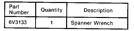
Tools Required:
Date Updated -12/10/2001

NOTE: The following photographs show the removal/installation procedure for a typical output transfer drive assembly. The procedure is similar for 'C' trucks and the D400 - where there are differences, these are noted and specific instructions are given.
1. Stop the truck in the straight ahead position and apply the parking brake. Move the gear lever to the Neutral position and stop the engine. Remove the key and place suitable warning notices to prevent personnel starting the engine and operating the controls. Use the hand lever on the suspension control valve to fully lower the front suspension.
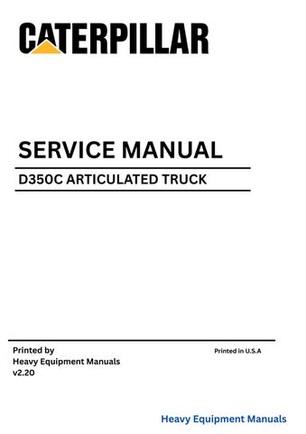
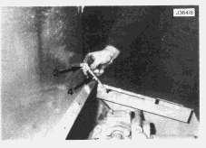
2. With the oil warm, remove the drain plug (1) and allow the oil to drain into a suitable container (C Truck - 35 litres) (D400 - 105 litres).
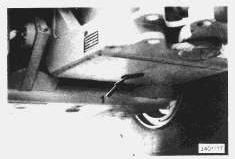
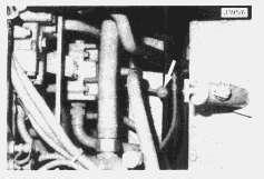
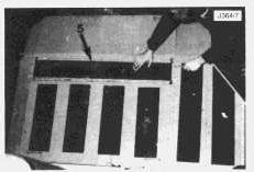
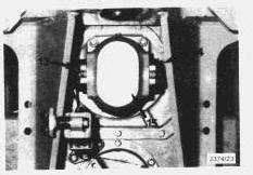
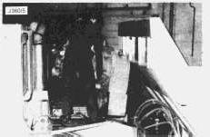
3. Remove the transmission compartment grille (2).
4. Release the retaining clips (3) from the access door struts (4).
5. Remove the rear access door assembly (5).
6. Disconnect and remove the hoist control linkage and rod assembly.
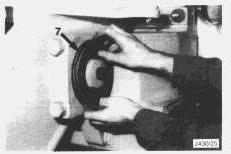
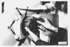
7. C-trucks: Remove the cam housing cover (6). Disconnect and remove the selector cable (7) from the housing. Refit the cover (6) to prevent dirt entering the housing.
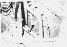
8. D400: Disconnect the torque converter lock up oil line (8) from the transfer gearbox.
9. D400: Disconnect the transmission control cables (9) from the rear of the transmission control group housing.
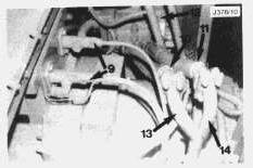
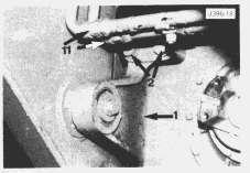
10. Trucks fitted with supplementary steering: Remove the supplementary steer hoses (10 and 11) from the diverter valve (12) to the pipes (13) and (14). Plug the ports on the diverter valve and cap the hoses to prevent contamination.
11. Trucks fitted with supplementary steering: Remove both pipe assemblies (13) and (14) from the supplementary steer pump.
12. Trucks fitted supplementary steering: Remove the supplementary steer pump (15).
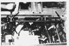
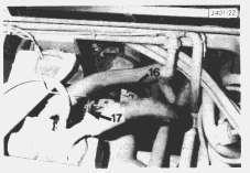
13. Remove the bolts that secure the transmission drive shaft (16). Remove the drive shaft. D400 (early trucks) - Disconnect the wires (17) from the magnetic pick-up. Mark the wires to ensure correct reconnection.
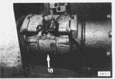
14. Remove the bolts that secure the spider (18). Remove the spider.
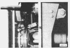
15. Remove the cotter pin (19) and the clevis pin (20) from the differential lock actuator.
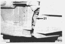
16. Remove the bolts securing the output transfer drive rear output yoke to the centre drive shaft (21). Slide the centre drive shaft backward.
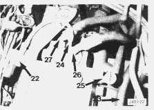
17. D400 - Remove the bolts securing the torque converter valve group (22) to the transmission mounting bracket. Disconnect the valve group oil supply line (24). Move the valve group to allow clearance when the transmission and output transfer drive assembly is hoisted out of the compartment. Remove the oil filler tube assembly (25). Disconnect the remaining oil lines (26) and (27) from the front of the transmission. Disconnect the oil cooler return line (23).
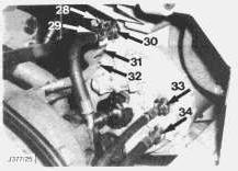
18. C Trucks - Disconnect the oil lines (28-34) from the front of the transmission. Mark the oil lines to ensure correct reconnection. Plug the ports and cap the hoses to reduce oil spillage and prevent contamination.
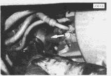
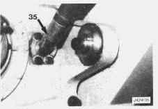
19. All trucks - Disconnect the sump line connection (35) from the output transfer drive housing.
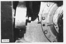
20. D400 - Disconnect the torque converter drain line (36) from the output transfer drive housing.
This is the sample of the manual if you need complete manual click on the Download button
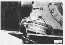
21. Remove the upper bolts (37) securing the left and right hand mounting brackets (38).
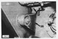
NOTE: On current trucks it is not necessary to remove the left and right hand mounting brackets.
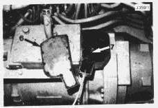
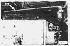
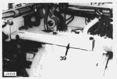
22. Remove the bolts securing the upper transmission mounting assembly (39). Remove the mounting assembly. Remove the torque converter selector valve (40) to provide more clearance.
NOTE: Place a wooden plank or similar form of protection at the rear of the transmission compartment. This will prevent damage to any components when the upper transmission mounting assembly is removed and the transmission/output transfer drive assembly pivots backwards.
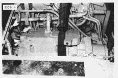
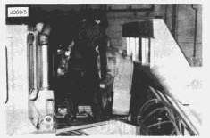
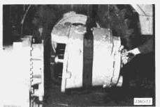
23. Place a suitable hoisting sling around the assembly as shown and connect the sling to a hoist.
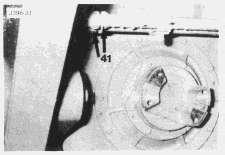
24. Early trucks: If necessary, disconnect the steering line pipe connections (41), also ...
It is important that the complete assembly is securely supported by the hoist and sling during the following procedure. This will prevent the assembly from moving downward when finally released from the truck frame, thus avoiding the possibility of injury or damage.
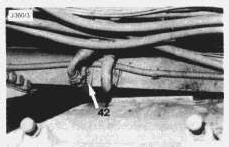
25. Early trucks: ... slacken the mounting brackets for both pipes (42) to allow sufficient movement of the pipes to provide clearance for the output transfer drive assembly during the hoisting procedure.
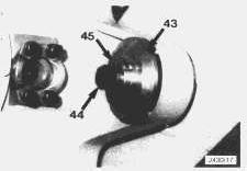
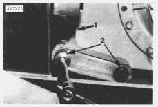
26. Drill out the indented lip of the locating ring (43) and remove the locating ring using tool 6V3133 Spanner Wrench. Remove the bolts (44) from the left and right hand pivot pins. Remove the pivot pins (45).
27. Remove the remaining lower bolts (46) from the left and right hand mounting brackets. Remove both mounting brackets (38).
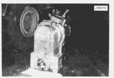
28. Hoist the complete transmission/output transfer drive assembly out of the truck.
29. Lower the assembly on to suitable stands, disconnect the hoist and remove the sling.
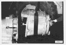
30. Attach a sling and hoist to the transmission. Install two 3/8 - 16NC forcing bolts (47) to separate the transmission from the output transfer drive. Remove the transmission from the output transfer drive. The weight of the transmission is 622 kg (1370 lb.).
31. End by:
(a) Disassemble output transfer drive.
(b) Disassemble transmission - see CAT Form Number SENR 2393 '615 Tractor-Scraper Power Train-Disassembly and Assembly' which can be found in CAT Service Manual SENR 2386 '615 Tractor-Scraper'.
Install Output Transfer Drive
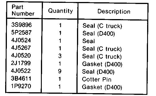
New Parts Required:
1. Start by:
(a) Assemble output transfer drive
(b) Assemble transmission - see CAT Form Number SENR 2393 '615 Tractor-Scraper Power TrainDisassembly and Assembly' which can be found in CAT Service Manual SENR 2386 '615 TractorScraper.'
(c) Assemble transmission to output transfer drive using 3S9896 or 5P2587 seal as appropriate.
2. Attach a sling and connect to a hoist. Lower the assembly into position in the transmission compartment. Take care when lowering past the steering system pipes. The two pipes, slackened previously in "Remove Output Transfer Drive" procedure - steps 24 and 25, can be moved to provide the clearance necessary to position the assembly in the compartment.
It is important that the complete assembly is securely supported by the hoist and sling during this procedure.
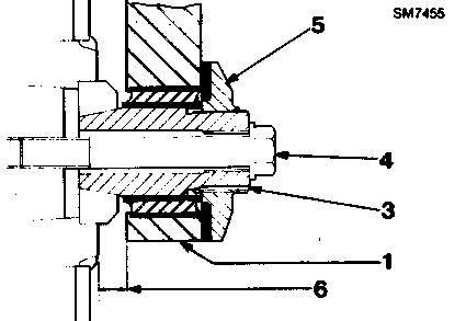
3. Position the left and right hand mounting brackets (1) against the output transfer drive. Install the lower bolts and washers (2) initially and fully tighten to a torque setting of 360±47 Nm (265±35 lb.ft.).
NOTE: On current trucks the transmission and output transfer drive assembly can be installed with the left and right hand mounting brackets in position.
4. Position the assembly so that the pivot pins (3) can be installed through the right and left hand mounting brackets (1). Install the pivot pins. Be sure the slot in each pin is facing towards the front of the truck.
5. Install the bolts (4) and washers and tighten to a torque setting of 360±47 Nm (265±35 lb.ft.).
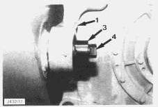
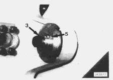
6. Install the locating ring (5). Use tool 6V3133 Spanner Wrench to tighten the locating ring until it just touches the face of the mounting bracket (1). Measure the gap (6) on each side of the truck and adjust the locating rings until both dimensions are equal to within 2mm.
7. Lock the locating ring (5) in position by using a punch to indent the ring lip into the slot in each pivot pin (3).
8. Check the alignment of the transmission to the front axle. The centre lines of the transfer drive output shaft and the front differential input shaft must be within 1.5mm (0.06 inch) measured sideways. Measure by placing a straight edge across the machined surfaces of the respective yokes.
Shims (7) are installed between the bearing cap (8) and the front suspension frame (9). If adjustment is necessary remove shims from under one bearing cap and install the same shims under the bearing cap on the other side. Before carrying out adjustment slacken clamp bolts (10). Tighten fully after adjustment.
9. Install upper bolts (2) and washers to the left and right hand mounting brackets (1). Fully tighten to a torque setting of 360±47 Nm (265±35 lb.ft.).
10. Early trucks: Connect steering pipes (11).
11. Early trucks: Connect brackets (12) to the truck frame.
This is the sample of the manual if you need complete manual click on the Download button