

Product: INDUSTRIAL ENGINE
Model: D349 INDUSTRIAL ENGINE 61P
Configuration: D349 ENGINE 61P00001-UP
Operation and Maintenance Manual
D346, D348 AND D349 INDUSTRIAL
Media Number -SEBU5405-02
Automatic Start-Stop
ENGINES
Date -01/05/1983
Updated -11/10/2001
An automatic start-stop system is used when an engine must start when a specific condition occurs and with no one in attendance. The engine will start, increase speed, pick-up the load, operate the load until a second condition occurs, remove the load, cool and stop. The following conditions must exist for the engine to start unattended:
1. Either the ambient (engine room) temperature must be at least 70°F (20°C); or, the engine jacket water temperature must be at least 90°F (32°C). A jacket water heater can maintain this temperature.
2. If a prelube oil pump is used (large bore engines), the pump must operate before the starting motor(s) are energized, and stop when the engine starts and oil pressure increases.
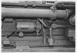
Protection Devices
The engine's control panel may be equipped with protection devices to protect the engine while cranking,
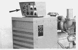
Batteries:
Lights can indicate if a fault has occurred in the battery charging system causing the battery to be either undercharged or overcharged.
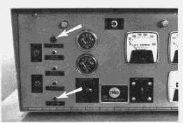
Overcranking:
A timer allows the engine to crank either once for 30 seconds, or to crank through 5 ten-second cranking cycles (depending upon the device used) while unattended. If the engine does not start before the time elapsed, the fuel system will be shutoff and a light will indicate a starting failure.
Engine Operation:
Prealarm systems provide an audible and/or a visual indication for low oil pressure, high water temperature, low fuel supply or low jacket water temperature before the condition becomes critical. These alarms are self resetting when the condition is corrected.
The engine may also be equipped with shutdown devices. If low oil pressure, high jacket water temperature or an engine overspeed condition occurs, the engine will be shutdown and a corresponding light will indicate the cause of the shutdown. These devices must be reset after repairs have been made and before starting. See the topic, EMERGENCY SHUTOFF DEVICES AND ALARMS.
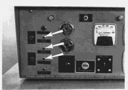
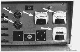
If the engine is equipped with an electric set, the control panel should be equipped with an ammeter, a frequency meter and a voltmeter. Depending upon the type of operation, the panel may also be equipped with other meters and lights. Know these instruments and their normal readings. They will indicate how the engine is performing.
This is the sample of the manual click on the download link for complete manual
DOWNLOAD LINK
For some reason if link does not work download this pdf and then click
Shutting Down:
A timer allows the engine to remove or transfer the load, and to continue running for up to 2 minutes for cooling purposes before stopping.
Engine Exerciser:
At present times, the exerciser will start, run and stop the engine in order to ensure both proper lubrication of all engine parts and proper equipment operation if and when the standby unit is needed.
Become familiar with all instructions included with the equipment. Copyright 1993 - 2024 Caterpillar Inc. All Rights Reserved. Private Network For SIS Licensees.
Product: INDUSTRIAL ENGINE
Model: D349 INDUSTRIAL ENGINE 61P
Configuration: D349 ENGINE 61P00001-UP
Operation and Maintenance Manual D346, D348 AND D349 INDUSTRIAL ENGINES
Determining Cause Of Shutdown NOTICE
If the engine has been shutdown by a safety device, do not start the engine and place it into service without having the cause of the shutdown investigated and corrected.
Low Oil Pressure Checks:
If the low oil pressure shutoff control has stopped the engine, make the following checks:
1. Check the water temperature gauge. Determine if the engine was overheated. Check for external water leaks.
Beware of steam or scalding water. Do not attempt to loosen the radiator cap until the temperature gauge indicates the coolant has sufficiently cooled. Then, loosen the cap slowly.
2. Check the oil level. Oil level must be between the ADD and FULL marks on the side of the dipstick stamped CHECK WITH ENGINE STOPPED.
3. If the oil level is below the ADD mark, check for oil spray and/or oil accumulations. If any are found, have the necessary repairs made. Before starting, add oil to the FULL mark.
4. Reset the shutoff control.
5. Remove the load and start the engine at its slowest speed. Be prepared to shut the engine down manually.
6. Be alert for unusual sounds or noises. If the engine knocks, stop the engine immediately and call your Caterpillar dealer.
7. If the engine blows excessive black exhaust or has excessive crankcase blow-by, the engine may need reconditioning. Stop the engine and call your Caterpillar dealer.
8. If the engine runs satisfactorily, observe the oil pressure gauge. If satisfactory pressure is not indicated, shut the engine down; call your Caterpillar dealer.
9. If proper oil pressure is registered, check to see if the reset knob has moved to the run position. If the knob does not move, stop the engine. Check the shutoff control, the oil line, and the oil pressure gauge. Have necessary repairs made.
10. If the oil pressure gauge registers normal oil pressure, if the knob on the shutoff control moves to the run position, and if the engine operation is otherwise satisfactory, determine if the high water temperature shutoff may have shut down the engine.
High Water Temperature Checks - Engine Running:
1. Determine if the load was too great for the engine: Reduce the load and allow the engine to cool while running.
2. If pressure steam or water leaks are visible, remove the load and stop the engine. Have necessary repairs made.
3. Check for collapsing or deteriorated water hoses. Have repairs made.
4. Check for noisy water pump operation. Have necessary repairs made.
5. Refill the cooling system with a solution of water and permanent type antifreeze if below freezing temperatures are expected; or with a solution of approved water and Caterpillar Corrosion Inhibitor. Follow the instructions on the container.
DO NOT remove the pressure cap on an overheated engine. The coolant is under pressure and relieving the pressure will cause the coolant to flash into steam. Serious flash burns and engine damage can result. If necessary, reduce pressure in a surge tank by pouring warm water on top of the tank. Never add cold water to a hot engine.
NOTE: If there is adequate coolant in the cooling system, gradual cooling is preferred by running the engine at half speed. This eliminates hot spots in the engine, and possible failure.
High Water Temperature Checks - Engine Stopped and Cold:
1. Check coolant level. Determine if the coolant has proper antifreeze protection. A 50-50 solution of permanent type antifreeze and approved water will give protection below -20°F (-29°C).
2. Check to be sure the raw water valve has been opened.
3. Check water pump drive belts for proper tension; see the LUBRICATION AND MAINTENANCE PROCEDURES topic, Fan Belts.
4. Check engine room vents and/or louvers. Be sure the engine is receiving sufficient air.
5. Be sure temperature regulators are operating at proper temperature range.
6. Inspect all water hoses carefully for collapsing, external and internal failures. Replace hoses as required.
7. Have the cooling system cleaned.
NOTICE
If severe or prolonged overheating has occured, contact your Caterpillar dealer to have your engine checked for possible damage.
Copyright 1993 - 2024 Caterpillar Inc. All Rights Reserved. Private Network For SIS Licensees.
Mon Apr 8 23:03:57 UTC+0530 2024
Product: INDUSTRIAL ENGINE
Model: D349 INDUSTRIAL ENGINE 61P
Configuration: D349 ENGINE 61P00001-UP
Operation and Maintenance Manual D346, D348 AND D349 INDUSTRIAL ENGINES
Emergency Shutoff Devices And Alarms
Emergency shutoff devices are either electrically, mechanically or hydraulically operated. Familiarize yourself with the types and locations of the shutoff devices, the conditions which cause each control to function, and the resetting procedure required to start your engine.
NOTICE
Always determine the cause of the shutdown, and have the necessary repairs made before restarting the engine.
Emergency shutoff controls are for emergency use only. Do not use an emergency shutoff device for a normal stopping procedure.
Electric Shutoff Controls
The operation of all electric shutoff controls is similar: A critical operating condition actuates a switch in the sensing unit. The switch closes the circuit to the shutoff solenoid which moves linkage to bypass the fuel to the cylinders; thus stopping the engine. The shutoff control may require resetting before the engine can start.
High Water Temperature Shutoff:
The shutoff switch is located in the water temperature regulator housing. Excessive water temperature closes the switch. No resetting procedure is required: As the coolant cools, the switch opens.
NOTICE
The sensing element must be submerged in the coolant to operate. A low coolant level cannot actuate the shutoff.
Low Oil Pressure Shutoff Switch:
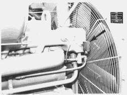
This device is usually mounted on the side of the engine with oil lines connected to the switch. Low oil pressure closes the switch.
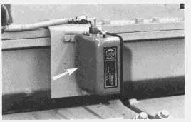
Manually operated systems require resetting of this switch before starting. Automatic start-stop systems use a pressure switch which resets itself.
To reset the switch, push the button until it latches. After the engine starts and develops oil pressure, the oil pressure will push the button to the extended running position.
NOTICE
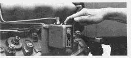
The engine will not be protected if the engine is operated with the button latched in the START position.
If the button remains in the reset position, the engine oil pump is not developing normal oil pressure and a check should be made.
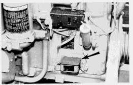
Overspeed Shutoff Switch (Electro-Mechanical):
This switch is mounted either on the tachometer drive or on the governor. Excessive engine speed closes a switch by centrifugal force.
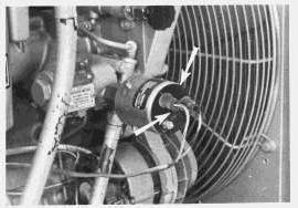
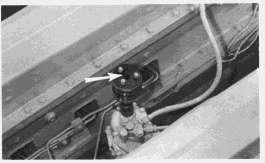
TWO INSTALLATIONS OF OVERSPEED SWITCH
To reset the switch, push the button marked RESET. The knob will remain down until the engine overspeeds.
Overspeed Shutoff Switch (Electronic):
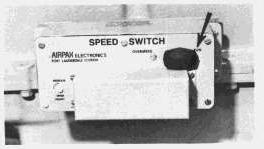
This switch is a magnetic pick-up which is mounted on the flywheel housing and senses engine speed. The control box is mounted on the engine block. Excessive engine speed closes a circuit breaker. To reset the switch, push arm of breaker to the run position.
NOTICE
This switch will not provide overspeed protection if there is no power to the control box.
Fuel/Oil Pressure Switch:
This switch is mounted in the fuel manifold between the clean side of the fuel filter and the fuel injection pump housing. Low fuel pressure (below 3 psi) opens the switch and the electrical circuit to either the shut off solenoid or the circuit between the alternator and the alternator regulator. Opening of these circuits prevents the battery from becoming discharged while the engine is stopped.
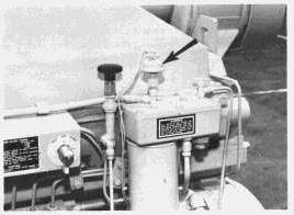
This switch can also be used with an electric governor. In this application, oil pressure closes the switch to allow the electric governor to control engine speed.
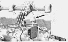
This switch does not require resetting.
Mechanical Safety Shutoff Control
The mechanical safety shutoff is both a low oil pressure and an overspeed shutoff device. A high water temperature shutoff can be installed which uses the low oil pressure shutoff device to stop the engine.
On 6 cylinder engines, the mechanical shutoff is mounted on the side of the engine. On vee engines, the shutoff is mounted in the vee of the engine between the two banks of cylinders.
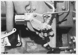
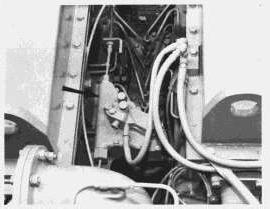
The high water temperature shutoff is installed in the temperature regulator housing of all engines.
If an overspeed, low oil pressure, or high water condition occurs, a spring loaded rod is mechanically tripped internally, which moves and holds the rack in the shutoff position.
Difficult starting with long periods of cranking can trip the low oil pressure shutoff. The reset lever must be moved and latched in the run position before starting can be accomplished. Normal stopping of the engine will not trip the shutoff device.
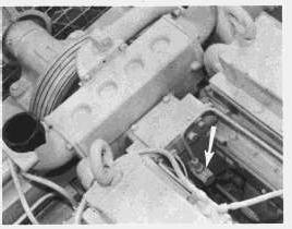
The basic cause for the shutdown can be determined by the manner in which the shutoff must be reset:
1. Push the reset lever (or handle).
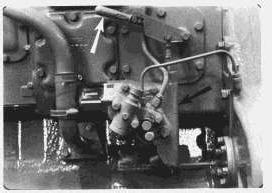
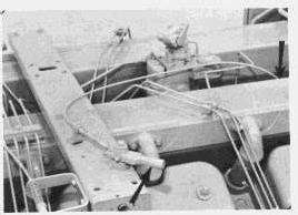
If the rod latches, an overspeed condition stopped the engine. Investigate the cause for overspeed condition.
If the rod does not latch, the engine was stopped because of a low oil supply to the shutoff control. This could be caused by either low engine oil pressure, or by the high water temperature shutoff bypassing the oil to the mechanical shutoff. Therefore, perform checks for both low oil supply and high water temperature. Reset the control by the following steps:
1. Push the reset button firmly.
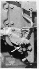
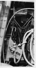
2. Push the reset lever (or handle) until the rod latches.
If the reset lever does not move freely, check the reset cable for kinks, binds, or lack of lubrication. Make needed repairs or adjustments.
Air Safety Shutoff Control
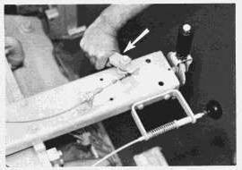
The air shutoff control is an attachment to the mechanical safety shutoff device installed on large bore vee type engines. When an emergency condition occurs, the mechanical shutoff pushes the rack into the shutoff position and pulls a butterfly valve, located in each inlet manifold, to the closed position. The air safety shutoff control must be reset before starting.
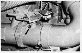
If an overspeed condition shut the engine down:
1. Pull the air shutoff reset lever on the air inlet manifold to the RESET position.
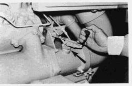
2. Release the lever. The lever should move slightly and then latch in the RUN position.
3. Push the mechanical shutoff reset lever until the rod latches.
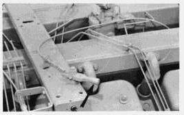
If a low oil pressure or high water temperature condition shut the engine down:
1. Firmly push the reset button in the vee of the engine.
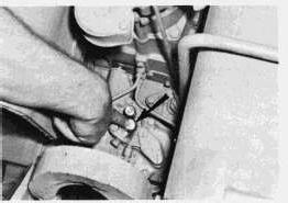
2. Pull the air shutoff reset handle on the air inlet manifold to the RESET position.
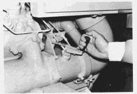
3. Release the lever. The lever should move slightly and latch in the RUN position.
4. Push the mechanical shutoff reset lever until the rod latches.
Hydraulic Shutoff Controls
The hydraulic shutoff control is mounted on (or near) the governor. When oil pressure drops below 8 PSI, the fuel injection pumps bypass the fuel to the cylinders.
To start the engine, move and hold the reset lever against the stop while cranking the engine. After the engine starts, the lever will stay in the running position. Manually reset the control each time the engine is stopped.
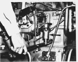
A high water temperature shutoff can be used with this shutoff control. Excessive coolant temperature causes the temperature sensor to open a dump valve which empties the pressure oil from the low oil pressure shut off device. The low oil pressure shutoff control shuts down the engine.
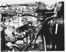
Reset the oil pressure control as instructed above. Allow the water sensor to cool: No resetting of the water temperature shutoff switch is required.
NOTICE
The water temperature sensor must be submerged in the coolant to operate. A low coolant level, or a failed water pump cannot actuate the shutoff.
Alarm Switches
Alarm switches are set at a less critical temperature, pressure, or level limit than the comparable shutoff control. The purpose of the alarm switch is to warn the operator an unsafe operating condition is starting to occur, and that corrective measures should be taken to avoid possible damage to the engine and/or a possible shutdown of the engine.
NOTICE
It could be hazardous to have the engine stop unexpectantly when engine power is needed. However, if the engine overspeeds, the engine should be stopped immediately.
When the preset temperature, pressure or fluid level occurs, the sensor of the alarm switch will move and close an electrical circuit. Either a light or an audible alarm will be energized. The light or alarm will continue to operate until the condition is corrected. When the condition is corrected the alarm will automatically reset and the light will turn off.
NOTICE
The cause of the shutdown must be investigated and corrected before starting and operating the engine.
Alarm Shutoff Switch:
This is the sample of the manual click on the download link for complete manual
DOWNLOAD LINK
For some reason if link does not work download this pdf and then click