
Note: Use Bookmarks panel to navigate

Previous Screen

Product: ARTICULATED TRUCK
Model: D25D ARTICULATED TRUCK 1HK

Configuration: D25D, D30D ARTICULATED TRUCK 1HK00674-UP (MACHINE) POWERED BY 3306 ENGINE
Disassembly and Assembly
Comfort Series Seat For Caterpillar Machines
Media Number -RENR2165-12
-01/10/2013
Optimized Seat with Front Controls - Disassemble and Assemble
SMCS - 7324-015; 7324-016
Caterpillar Optimized Seat System (COSS) Seat
Disassembly Procedure
The air spring of the air suspension is filled with air pressure.
Prior to disassembly, release the air pressure in the air spring. Failure to do so could result in personal injury.
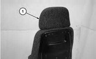
Illustration 1
1. Remove headrest (1) .
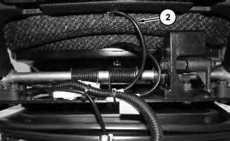
Illustration 2
2. Disconnect harness assembly (2) .
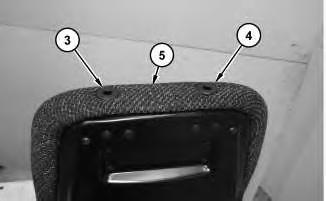
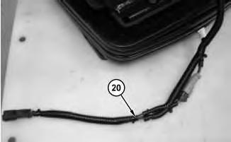
Illustration 3
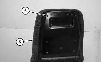
3. Turn tube (4) one-quarter turn counterclockwise and remove tube (4) from cushion (5) .
4. Turn tube (3) one-quarter turn clockwise and remove tube (3) from cushion (5) .
4
5. Remove four screws (6) and cushion (5) .
5
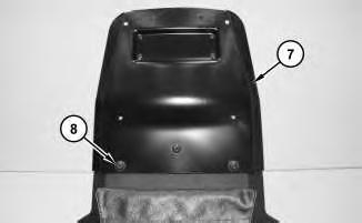
6. Remove three bolts (8) and pan (7) .
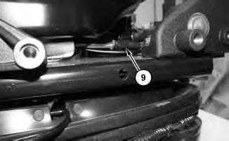
Illustration 6
7. Disconnect harness assembly (9) .
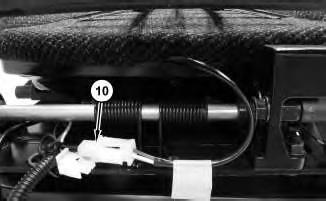
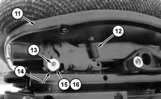
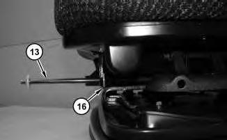
Illustration 9 g02423460
Right side of seat pan (11)
Personal injury can result from being struck by parts propelled by a released spring force.
Make sure to wear all necessary protective equipment.
Follow the recommended procedure and use all recommended tooling to release the spring force.
9. Adjust seat pan (11) to the lowest position, as shown.
10. Remove springs (12) on both sides of seat pan (11) .
11. Remove retainer (15) and nylon washer (16) on the left side of seat pan (11) .
12. Remove rod (13), nylon washer (14), and nylon washer (16). Remove seat pan (11) .
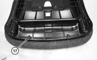
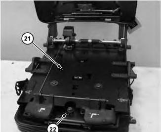
Illustration 10
13. Remove screws (17) .
g02423377
13
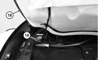
16. Remove bolt (22). Slide upper seat assembly (21) forward in order to remove upper seat assembly (21) .
14
15
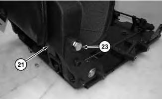
17. Recline upper seat assembly (21) to the farthest reclined position.
18. Mark the location of upper seat assembly (21) in sprocket (27) for assembly purposes.
19. Remove bolt (23) from upper seat assembly (21). Repeat for the other side.
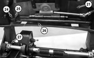
20. Loosen jam nut (25). Hold rod assembly (26) while you turn bolt (24) clockwise in order to retract bolt (24). Retract bolt (24) into rod assembly (26) until upper seat assembly (21) comes free from the lower seat assembly.
Personal injury can result from being struck by parts propelled by a released spring force.
Make sure to wear all necessary protective equipment.
Follow the recommended procedure and use all recommended tooling to release the spring force.
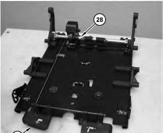
21. Lift lever (29) and use suitable Tooling to rotate the shaft of recliner assembly (28) towards the rear until the shaft stops rotating. There will still be spring pressure, however this action will reduce the existing spring pressure on recliner assembly (28) .
17
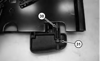
22. Remove allen screw (31). Remove cable (30) .

18
Personal injury can result from being struck by parts propelled by a released spring force.
Make sure to wear all necessary protective equipment.
Follow the recommended procedure and use all recommended tooling to release the spring force.
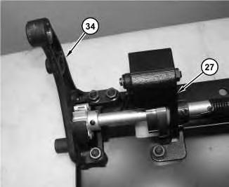
23. Position suitable Tooling (33) through the anchored loop of spring (32). This action should help control the sudden release of spring (32) during the removal of recliner assembly (27) .
Personal injury can result from being struck by parts propelled by a released spring force.
Make sure to wear all necessary protective equipment.
Follow the recommended procedure and use all recommended tooling to release the spring force.
Note: Keep your hands clear of the spring on the recliner assembly. Remaining tension will release when recliner assembly (27) is removed.
24. Remove bracket assembly (34). Remove recliner assembly (27) .
20
Personal injury can result from being struck by parts propelled by a released spring force.
Make sure to wear all necessary protective equipment.
Follow the recommended procedure and use all recommended tooling to release the spring force.
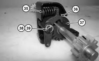
Note: Mark the location of recliner lock (36) in sprocket (37) for assembly purposes.
25. Use a suitable pair of needle nose pliers in order to grasp spring (35). Carefully compress spring (35) and remove spring (35) .
26. Remove clip (38), nylon washer (39), and recliner lock (36) .
21
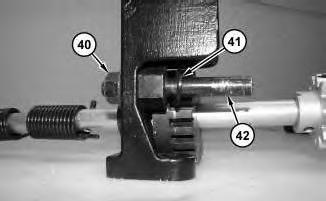
27. Remove nut (40). Remove washer (41) and rod (42) .
Personal injury can result from being struck by parts propelled by a released spring force.
Make sure to wear all necessary protective equipment.
Follow the recommended procedure and use all recommended tooling to release the spring force.
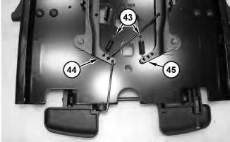
28. Mark the holes in latch assemblies (44) and (45) where springs (43) are attached for assembly purposes. Remove springs (43) .
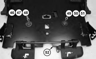
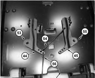
Illustration 24
g02428245
29. Loosen bolts (46) and (49) from plate assembly (52) .
30. Mark the holes in latch assemblies (44) and (45) where rods (54) and (56) attach to latch assemblies (44) and (45) .
31. Remove bolts (46) and (49). Remove hard washer (47) and (50). Remove nylon washers (48) and (51) .
32. Remove latch assemblies (44) and (45) and rods (54) and (56) from plate assembly (52). Remove nylon washers (53) and (55) .
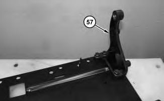
Illustration 25
33. Remove bracket assembly (57) .
g02427642
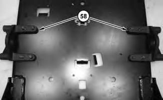
26
34. Remove seat mounted control brackets (58) .
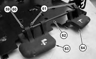
Illustration 27
g02428878
Note: Note the installation order of two retainers (59), two nylon washers (60), two nylon washers (61), lever (63), and lever (64) on rod (62), for assembly purposes.
35. Remove retainer (59) and nylon washer (60). Repeat for the other side of rod (62). Remove lever (63), lever (64), and two nylon washers (61) from rod (62) .
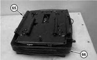
Illustration 28
g02428879
36. Remove slider blocks (65). Remove rubber boot (66) .
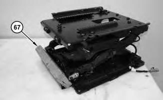
Illustration 29
g02428880
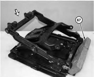
37. Raise the suspension assembly far enough to install suitable cribbing (67) .
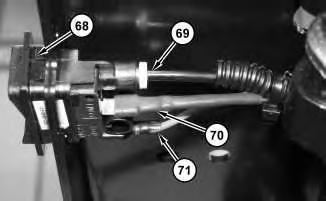
Illustration 30
g02429016
38. Disconnect hose (69), harness assemblies (70) and (71). Remove switch assembly (68) .
32
33
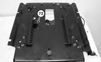
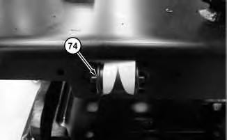
41. Remove spool (74). The ride zone indicator tape will not be removed at this time.
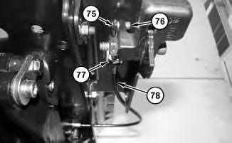
42. Remove nut (75) and bolt (76). Loosen jam nut (77). Disconnect cable assembly (78) .
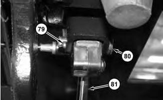
High pressure cylinder. Do not remove any parts until pressure has been relieved or personal injury may occur.
Note: Cylinder (81) is under pressure of nitrogen gas. use caution when disconnecting cylinder (81) .
43. Remove cotter (79) and pin (80) in order to disconnect cylinder (81) .
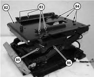
Illustration 36 g02430518
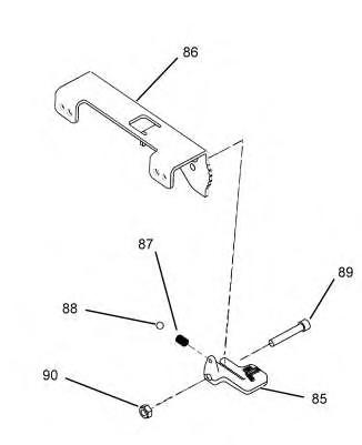
Illustration 37 g02431181
Personal injury can result from being struck by parts propelled by a released spring force.
Make sure to wear all necessary protective equipment.
Follow the recommended procedure and use all recommended tooling to release the spring force.
44. Remove lever (85). Remove bracket assembly (86). Remove bolts (83). Remove bolts (84). Remove plate assembly (82) .
45. Remove nut (90), bolt (89), and lever (85). Remove ball (88) and spring (87) .
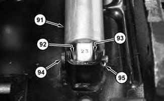
46. Remove cotter (95). Remove pin (94), bearing (92), and washer (93). Remove cylinder (91) .
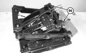
47. Remove bearing blocks (96) .
40
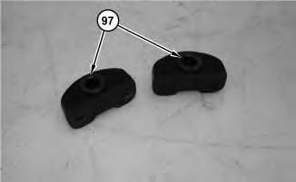
48. Remove nylon bearings (97) .
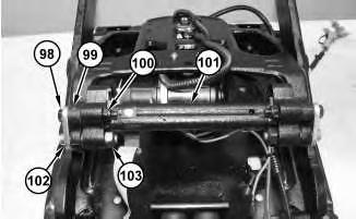
Illustration 41
49. Remove nut (100), bolt (98), and spacer (99). Remove nut (103) and retainer (102). Repeat for the other side. Remove upper link (101) .
42
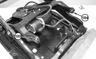
50. Remove nylon bearing (105). Repeat for the other side.
51. Remove nylon bearing (104). Repeat for the other side.
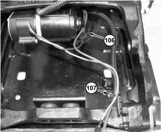
Illustration 43
52. Disconnect harness assembly (106). Cut cable strap (107) .
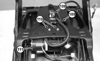
Illustration 44
53. Cut cable strap (109). Disconnect hose (108). Remove screws (110). Remove compressor assembly (111) .
45
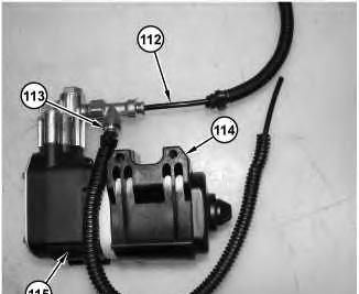
54. Remove hoses (112) and (113). Remove clamp (114) from compressor (115) .
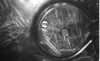
Illustration 46
55. Remove screw (116) .
g02430645
Personal injury can result from being struck by parts propelled by a released spring force.
Make sure to wear all necessary protective equipment.
Follow the recommended procedure and use all recommended tooling to release the spring force.
.

49
Pinch Point
Stay clear of this area!
Serious personal injury may occur.
Note: If you do not support the suspension assembly, the suspension assembly will collapse suddenly.
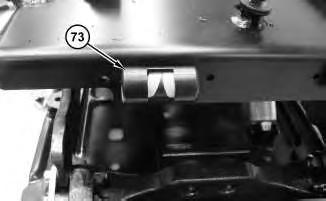
58. Support the suspension assembly and remove suitable cribbing (67). Allow the suspension assembly to slowly fold down.
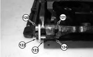
Illustration 50 g02434080
59. Remove nut (124). Remove bolt (122) and bushing (123). Remove bolt (121) and retainer (120) .
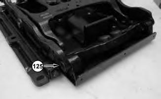
Illustration 51
g02434081
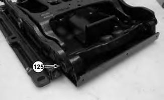
60. Remove nylon bearing (125). Repeat for the opposite side.
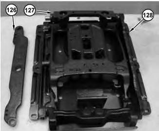
Illustration 52
g02434082
61. Remove link (126) and the nylon bearings. Remove link (127). Remove link (128) and the nylon bearings.
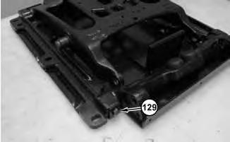
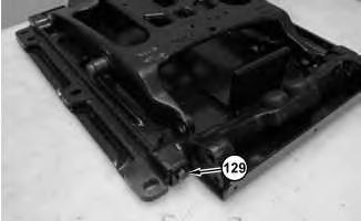
62. Remove bolt (129). Repeat for remaining three corners.
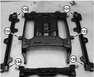
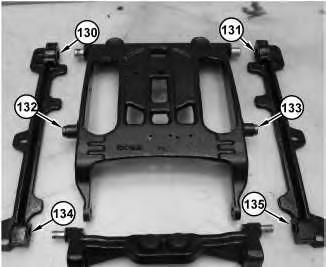
63. Remove nylon bearings (130) and (134). Remove nylon bearings (131) and (135). Remove nylon bearings (132) and (133) .
Assembly Procedure
55
1. Install nylon bearings (132) and (133). Install nylon bearings (131) and (135). Install nylon bearings (130) and (134) .
56
2. Install bolts (129). Repeat for three remaining corners.
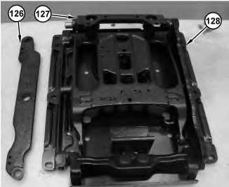
3. Install link (128) and the nylon bearings. Install link (127). Install link (126) and the nylon bearings.
58
4. Install nylon bearing (125). Repeat for the other side.
Improper assembly of parts that are spring loaded can cause bodily injury.
To prevent possible injury, follow the established assembly procedure and wear protective equipment.
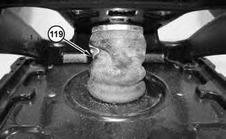
7. Install air spring assembly (119) .
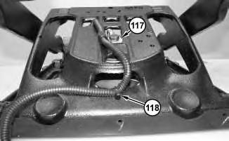
8. Connect clip (117). Install new cable strap (118) .