

Previous Screen
Product: ARTICULATED TRUCK
Model: D25C ARTICULATED TRUCK 9YC
Configuration: D25C ARTICULATED DUMP TRUCK 9YC00001-01011 (MACHINE) POWERED BY 3306 ENGINE
Operation and Maintenance Manual
D25C, D30C, D35C AND D350C ARTICULATED TRUCKS
Media Number -SEBU8646-00
Publication Date -01/08/1987
Every 250 Service Hours Or Monthly
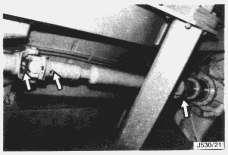
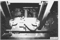
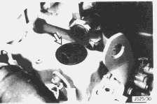
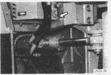
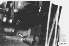
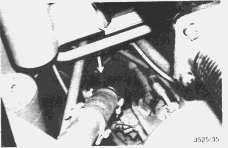
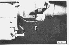
Drive Shafts
Lubricate Splines and Bearings
NOTICE
Date Updated -11/10/2001
Use a hand operated grease gun. Pressure greasing may damage the seals.
All Machines
Lubricate the transmission drive shaft splines and spider bearings through three fittings.
Lower the front suspension to the service position.
Lubricate the front drive shaft spider bearings through two fittings.
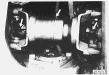
Lubricate the centre drive shaft splines and spider bearings through three fittings.
Two Axle Machines with Rigid Rear Axle.
Lubricate the front spider bearing
Lubricate the two spider bearings and the splines through three fittings.
Two Axle Machines with Rear Suspension
Lubricate the front spider bearing and the splines through two fittings.
Lower the rear suspension to the service position.
Lubricate the rear spider bearings and splines through two fittings.
Lubricate the two spider bearings and the splines through three fittings.
Lubricate the front spider bearings and splines through four fittings.
Lubricate the lower shaft rear spider bearing through one fitting.

Lubricate the spider bearings and splines through three fittings.
If all drive shaft grease fittings are lubricated regularly at the recommended interval only two or three shots will be required at each fitting.
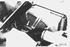
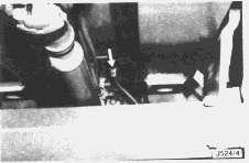
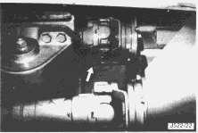
Fan Pulley
Lubricate Bearing
Lubricate the fan pulley bearing through one fitting.
If regular lubrication is carried out at the recommended interval only two or three shots will be required.
Cooling System
Add Conditioner
Cooling system conditioner contains alkali.
Contact with the skin or eyes will cause personal injury.
Take care when handling conditioner, wear protective clothing and safety glasses.
All waters rapidly become acidic at engine operating temperatures so that it is important that a 3% -6% concentration of cooling system conditioner is maintained at all times. However, too much
conditioner (greater than 6%) can result in damage to metals such as aluminium or to the solder used in the construction of some cooling system components because the coolant mixture can become over alkaline.
When adding conditioner follow the instructions on the container. Use Cat. part number 6V3542 (0,25 litres), 3P2044 (0,95 litres) or 5P2907 (208 litres). It will be necessary to add approximately 0,5 litres every 250 service meter hours to maintain the correct concentration but the only way to be certain is to test the coolant - see Caterpillar form number SEBD0518 - "Knowing your Cooling System".
NOTE: It may be necessary to drain a little coolant to allow for the addition of conditioner.
Engine Crankcase
Change Oil, Clean Breather and Change Filters
Hot oil and components can cause personal injury. Do not allow hot oil or components to contact the skin.
The machine must be level, the parking brake applied, the oil warm and the engine stopped.
1. Lower the front suspension to the service position - see the section "Lowering the Suspension".
2. Remove the crankcase drain plug and allow the oil to drain into a suitable container. Wipe the plug clean and install.
3. Remove and discard the old oil filter element.
NOTE: The filter will contain oil.
4. Clean the filter housing base. Make sure all of the old seal is removed.
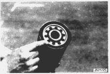
5. Apply a thin film of clean engine oil to the new filter seal.
6. Install the new filter and hand tighten by 3/4 turn after it contacts the base.
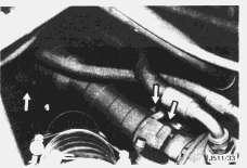
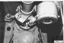
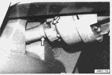
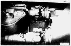
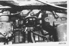
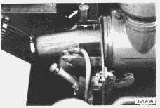
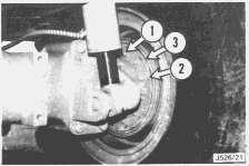
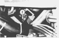
7. Release the hose clamp (1) and disconnect the fumes disposal tube.
8. Unscrew the retaining bolt (2) and remove the breather.
9. Wash the breather in solvent and wipe dry.
10. Inspect the breather seal and install a new one if damaged.
11. Install the breather and re-connect the fumes disposal tube.
12. Remove the fill cap and fill the crankcase with new oil. See the sections "Lubricant Specifications," "Recommended Lubricant Viscosities" and "Refill Capacities" for the type and amount of oil to use. Add oil to the SAFE STARTING RANGE WITH ENGINE STOPPED AND OIL COLD mark on the dipstick.
13. Block the trailer wheels, start the engine, release the park brake and allow the suspension to self level. Apply the park brake and inspect for leaks while the engine is running at low idle for two minutes.
14. Measure the oil level and add oil if necessary to between the ADD and FULL marks on the ENGINE RUNNING AT LOW IDLE WITH WARM OIL side of the dipstick.
15. Stop the engine.
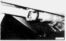
Air Dryer
Check Operation
Open the air reservoir drain tap and allow condensate to drain. A small amount of water is normal (particularly in areas where there is a large variation in ambient temperature (30°F/17°C or more) due to condensation within the tank. However, the presence of excessive water indicates that the air dryer dessicant cartridge needs changing.
It is suggested that the drain tap is opened every morning on a new truck in order to gain experience of how much water discharge (if any) is normal. Once this experience has been gained the drain tap need only be opened every 250 service meter hours.
Check the air dryer for correct operation.
Compressed air is released during this check.
This can cause personal injury.
Wear safety glasses and clothing.
1. Open the reservoir drain tap and allow air to exhaust for a short time. Allow the air pressure to fall to 620 kPa (90 p.s.i.). Close the tap.
2. Check the park brake is applied and the transmission selector is in neutral, then start the engine and allow to operate at low idle.
3. Observe the air dryer purge valve but do not get too close. As the air pressure increases the compressor will cut out and when that happens the purge valve should open and expel air under pressure. This purge operation should only last for a short time and regenerates the dryer dessicant cartridge.
If air continues to blow back through the purge valve the dryer needs immediate attention. It is likely that the internal non-return valve is leaking.
4. Stop the engine when the air system is fully charged.
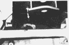
Alternator and Fan Belts
Inspect - Replace and/or Adjust
1. Inspect the belts for wear, fraying or cracking. If the belts are damaged replace them in complete sets. Never replace a single belt as the new one will carry all of the load and will rapidly fail.
2. Apply a 110N (25 lb) load perpendicular to the belt midway between the drive and driven pulleys. A correctly adjusted set will deflect between 15 and 20mm.
3. If adjustment is necessary loosen the clamp bolt and pull the alternator outward to obtain the correct deflection.
4. Tighten the bolt and check the tension.
NOTICE
If leverage is required be sure the bar bears against the alternator front plate.
Brakes
Test for Proper Function and Check Linings
All Axles on all Machines except D35C Rear
The wheel brakes are self adjusting and require no attention other than a periodic check to ensure that the brakes are in good working condition and that the linings are not excessively worn.
The parking brakes are released during this test.
Unless precautions are taken the machine may move, causing an accident.
To prevent movement block all wheels before the parking brakes are released.
1. Stop the machine on hard, level ground, block all wheels to prevent the truck from moving and stop the engine. Release the park brake.
2. Remove the brake dust covers (6 bolts).
3. Inspect the linings and measure the thickness. The minimum thickness of the brake linings is 8mm.
Make sure there is enough lining material to last through the next service interval.
4. Check the clearance between the brake linings and the drum. The brakes are self adjusting so that the clearance between the linings and the drum should never exceed 2mm.
If the clearance is greater than 2mm it is possible that the automatic adjuster is not working correctly.
Check the clearance between both linings and the drum.
5. Have an assistant press down the brake pedal and observe whether the brake shoes move freely into contact with the drum. Release the pedal and observe whether the brake shoes move freely away from the drum.
If the brake is sluggish in operation the cause must be investigated.
6. Replace the dust covers.
7. Repeat the entire procedure for each wheel brake in turn.
If any of the above checks are not satisfactory have the brake repaired before putting the machine back to work.
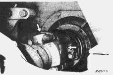
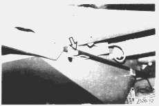
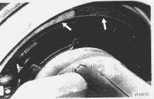
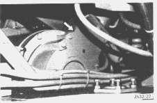
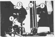
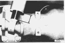
1. Stop the machine on hard, level ground and apply the park brake.
2. Inspect the brakes to make sure the frame bolts (1) are not loose, retractor springs (2) are not broken and that the brakes are not overheating. Overheating may be an indication that the brakes need bleeding. Check also that the frames (3) are undamaged.
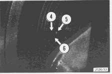
3. Look through the gap between the two halves of the brake frame to locate the lining (4) and steel shoe (5).
4. Scribe a line (6) on the frame 19mm (0.75in) from the outside edge.
5. Have the brake applied and compare the position of the steel shoe with the scribed line. If the outside edge of the shoe coincides with the line, travel is at a maximum and the brake must be relined.
Sufficient material must remain to last through the next service interval of 250 hours.
The brake expander tubes are subject to fatigue and must be replaced when they are cracked, charred or if the nozzle has been leaking. It is recommended that the tubes are replaced every 5000 hours or on a schedule established by service experience, and must be replaced when the brake shoes are relined. The expander tubes and shields are supplied as complete assemblies for ease of fitting.
If any of the checks carried out on the brakes are not satisfactory consult your nearest Caterpillar dealer. Do not put the machine back into operation until the brakes are working correctly.
Drive Line Park Brake
Test for Proper Function and Check Linings.
Checking the park brake for correct operation involves it being released. Ensure that the wheels are securely blocked and the machine is on hard, level ground. The park brake must be maintained in good working condition at all times.
1. Park the machine on hard, level ground, apply the park brake and shut down the engine.
2. Block all wheels.
3. Remove the brake dust cover.
4. Have an assistant operate the park brake lever, and observe that the operation of the brake is prompt both in application and release. If the operation of the brake is sluggish consult your Caterpillar Dealer.
5. Clean the end of clevis pin. It should be painted red. Offer up the cover plate and look through the hole to try and locate the end of the pin. If the end of the pin is in line with the hole the brake plates are fully worn and must be renewed.
6. Install the cover.
Do not operate the machine unless the park brake is operating correctly.
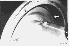
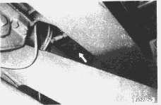
Axle and Gearbox Vent Valves
Clean or Replace if Damaged
Vent valves are installed in the following locations:
a) One in each drive axle.
b) One in the D35C transfer gearbox.
c) One in the D350C six wheel drive transfer gearbox.
Remove all vent valves, wash in clean solvent and install.
If damaged, install a new one.
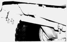
The front axle vent valve is remote mounted and is located at the front, right hand side of the transmission.
On two axle machines, the rear axle vent valve is located on the underside of the rear frame, adjacent to the drive shaft and forward of the differential.
On all three axle machines a vent valve is located under the rear frame above the centre axle Aframe.
On three axle machines with six wheel drive a vent valve is located under the rear frame above the rear axle A-frame.
On the D35C the transfer gearbox vent valve is located on the underside of the rear frame, above and to the right of the gearbox.
On six wheel drive machines the transfer gearbox vent valve is located on the underside of the rear frame, just in front of the centre axle A-frame.
Air Conditioner (if equipped)
Inspect, Clean and Adjust
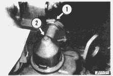
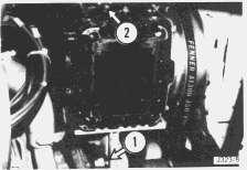
1. Unclip and open the cover.
2. Inspect the fan (1), evaporator coil (2) and condenser coil (3). Remove any trash or debris.
3. Inspect the unit hoses for wear or abrasion.
4. Check the refrigerant using the sight glass on the receiver/dryer (4).
If there is evidence of leakage or discolouration the system must be fully serviced. Consult your Caterpillar Dealer for service and information.
5. Check the compressor belt tension. The belt should deflect 51/2mm when a load of 28-35N (6.3 -7.9 lb) is applied mid-way between the drive and driven pulleys.
6. Adjust if necessary by slackening the nuts (1) and moving the compressor mounting bracket.
7. Tighten nuts (1) when the belt is correctly tensioned.
A loose belt will cause intermittent cooling and an overtight belt will overload the clutch, compressor bearings and the belt itself.
8. Use a piece of non-corrosive wire 3mm diameter and 210mm long to check the compressor oil level. Remove the plug (2), wipe the wire clean and check the oil level. There should be between 30mm and 32mm of oil in the compressor.
Make up oil should be perfectly clean. Use Suniso No. 5, Texaco, Capella E or equivalent.
9. Install the plug (2).
Suspension
Check Ride Height and Adjust if Necessary
Front Suspension - All Machines
1. Park the machine on hard level ground.
2. Lower the suspension to the service position. See the subject "Lowering the Suspension".
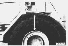
3. Measure the distance between the wheel arch and wheel rim.
4. Start the engine, check that differential lock is disengaged and release the park brake.
5. Allow the suspension to self level.
6. Apply the park brake and stop the engine.
7. Measure the distance between the wheel arch and rim. The dimension should be 145-175mm (5.70-6.88 in.) more than in the service position.
8. If the ride height is not within specification, adjustment will be necessary. Refer to the Service Manual or your Caterpillar Dealer.
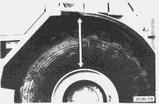
Rear Suspension - Three Axle Machines
1. Park the machine on hard level ground.
2. Measure the length of exposed chromed rod on the centre and rear axle suspension cylinders on one side of the machine.
3. Add the two dimensions together. The total length of chromed rod visible from the pair of cylinders should be either 145-150mm (5.70-5.90 in.) or 195-200mm (7.70-7.90 in.) depending on which cylinders are installed. Refer to the Service Manual or your Caterpillar Dealer for precise information.
4. Repeat for the other side of the machine.
5. If the suspension height is not within specification adjustment will be necessary. Refer to the Service Manual or your Caterpillar Dealer.
Rear Suspension - Two Axle Machines so Equipped
1. Park the machine on hard level ground.
2. Be certain that the machine will not roll and allow the engine to run at low idle with the park brake released and differential lock disengaged.
3. Allow both front and rear suspension to self level then apply the park brake.
4. Stop the engine. Measure the length of chromed rod visible from one of the rear suspension cylinders. There should be 80-100mm (3.15-3.98 in.) of rod visible.
Oscillating Hitch
Adjust Pin Clearance and End Float
1. Park the machine on level ground.
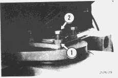
2. Slacken the locknuts (1).
3. Turn the adjusting screws(2) slowly and evenly to take up excessive clearance. DO NOT overtighten.
4. Tighten the locknuts.
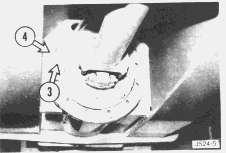
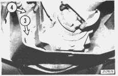
5. Remove the locking lug(3).
6. Tighten the thrust flange(4).
7. Back off the thrust flange until the locking lug locates in the next hole.
8. Install the locking lug.
Copyright 1993 - 2025 Caterpillar Inc. All Rights Reserved. Private Network For SIS Licensees. Tue Jun 17 16:21:29 UTC+0530 2025