

Previous Screen
Product: ARTICULATED TRUCK
Model: D250E ARTICULATED TRUCK 5TN
Configuration: D250E Articulated Truck 5TN00001-UP (MACHINE) POWERED BY 3306 Engine
Disassembly and Assembly
Comfort Series Seat For Caterpillar Machines
Media Number -RENR2165-12 Publication Date -01/10/2013 Date Updated -31/10/2013
Air Suspension With Toggle Switch Height AdjustmentDisassemble
SMCS - 7324-015-AJ
Disassembly Procedure
1. Remove the seat assembly from the machine. Separate the seat from the air suspension.
The air spring of the air suspension is filled with air pressure.
Prior to disassembly, release the air pressure in the air spring. Failure to do so could result in personal injury.
2. Use the following procedure to release the air pressure in the air spring:
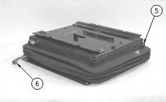
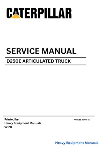
Illustration 1 g00291076
a. Connect a 24 volt power supply to two-pin connector (6). No. 1 connector pin is positive.
Note: The air spring will completely deflate in approximately 60 seconds.
b. Push down toggle (5). While you hold down the toggle, apply the 24 volt power supply for approximately 60 seconds.
c. Allow the air spring to deflate without any weight on the suspension.
d. Turn off the power supply when all the air has been released.
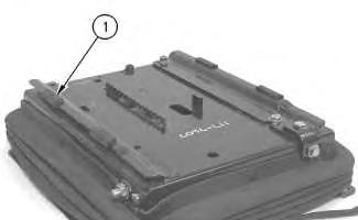
Illustration 2
3. Remove four slides (1) .
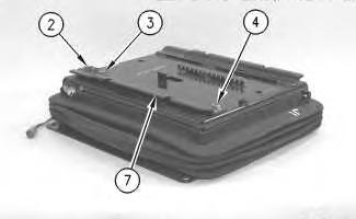
Illustration 3
g00291077
4. Remove two bolts (3), the washers, one bolt (2) and locknut (4). Remove fore and aft slider track (7) .
4
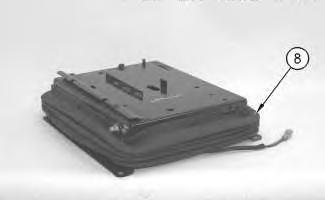
Remove boot (8) .
5
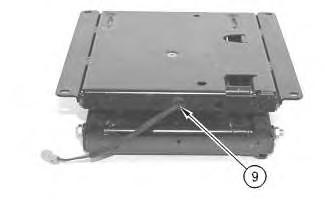
6. Remove bushing (9) .
6
7
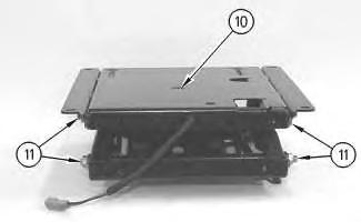
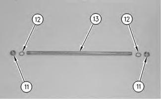
7. Remove four locknuts (11) and lock washers (12). Remove two shafts (13) .
8. Remove bolt (10) from the air spring, which is not shown.
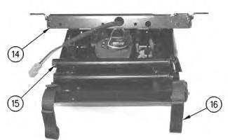
Illustration 8
g00275777
9. Disconnect two tether belts (16) and the damper from lower housing (14). Separate lower housing (14) from scissor assembly (15). Tip lower housing (14) while you slide the lower housing from scissor assembly (15) .
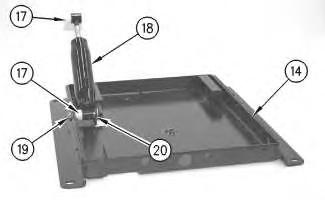
Illustration 9
g00275778
10. Remove nut (19), pin (20), two bearings (17) and damper (18) from lower housing (14) .
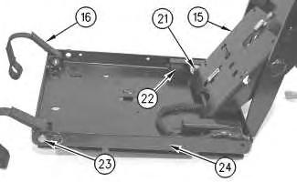
Illustration 10
g00275780
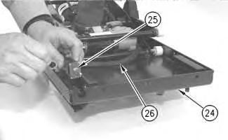
Illustration 11
g00275782
11. Remove one bumper (22). Remove scissor assembly (15) from upper housing (24) by twisting the scissor assembly off rollers (21). Remove bolt (23) and the locknut. Remove tether belts (16) from each side of upper housing (24) .
12. Remove the tie-wraps from wiring harness (26). Disconnect wiring harness connection (25) and the washer from upper housing (24) .
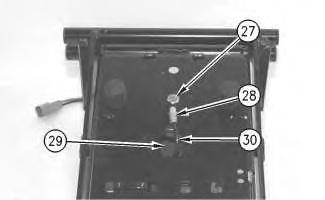
Illustration 12
g00275783
13. Remove bolt (27) and air spring (29). Use a small wrench to press fitting (28) while you pull tube (30) out of fitting (28) .

Illustration 13
g00275785
14. Put identification marks on two electrical connectors (31) for installation purposes. Disconnect two electrical connectors (31). Cut tie-wraps (32) that are holding wiring harness (26) to scissor assembly (15). Remove wiring harness (26) .
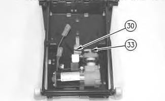
Illustration 14
15. Remove tube (30) from fitting (33) .
g00275786
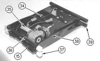
Illustration 15
g00275788
16. Remove clamp (36) and tie-wrap (38) from air compressor (35). Remove air compressor (35) from scissor assembly (15) .
17. Remove four bushings (39) and four rollers (37). Remove two rubber bumpers (34) . Copyright 1993 - 2025 Caterpillar Inc. All Rights Reserved. Private Network For SIS Licensees.
This is the sample of the manual if you need complete manual click on the Download button