

Previous Screen
Product: ARTICULATED TRUCK
Model: D250D ARTICULATED TRUCK 6NG
Configuration: D20D & D250D ARTICULATED TRUCK 6NG00001-UP (MACHINE) POWERED BY 3116 ENGINE
Disassembly and Assembly
Comfort Series Seat For Caterpillar Machines
Mechanical Suspension With Fixed Damper - Assemble
SMCS - 7324-016-ME
Assembly Procedure Table 1
1. Check the condition of all parts of the mechanical suspension. If any of the parts are worn or damaged, install new parts.
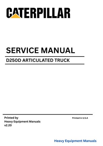
2. Install two brackets (58) on upper housing (7). Install the washers, four bolts (60), two bolts (59), and the locknuts on two brackets (58). Tighten the bolts to a torque of 25 ± 6 N·m (18 ± 4 lb ft).
2
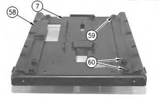
3. Install indicator band (56) and new tie-wraps (55). Install pin (57) in the bracket.
3
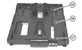
4. Install height adjustment lever (54) and handle (53). Install the key for the height adjustment lever.
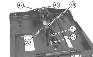
Illustration 4
g00288354
Note: Apply 5N-5561 Lubrication Compound on the roller shafts before installation.
5. Install arm assembly (51) and spring (52). Install roller (48), two spacers, and the pin. Install retaining ring (47). Install roller (49) and the pin. Install retaining ring (50). Make sure that the rollers do not bind.
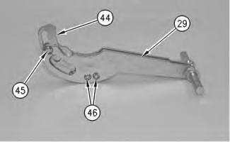
Illustration 5
g00288352
6. Install cam (44) in suspension arm (29). Install retaining rings (45) and (46) and the pins.
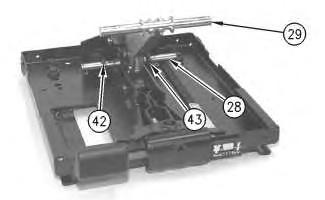
Illustration 6
g00288351
7. Install the shaft and suspension arm (29). Install spacers (42) and (43) on shaft (28).
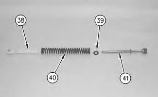
Illustration 7
g00288350
8. Install rod assembly (41), retainer (39), spring (40) and guide bushing (38). Assemble spring assembly (37) .
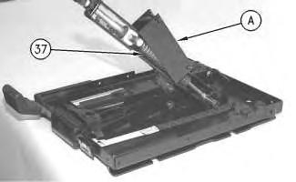
Illustration 8
g00288349
9. Attach Tool (A) to spring assembly (37), as shown. Slowly compress spring assembly (37). Use Tool (A) to install the spring assembly on the shaft.
10. Repeat Steps 8 and 9 for the spring assembly on the other side of the suspension arm.
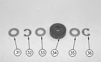
Illustration 9
g00288348
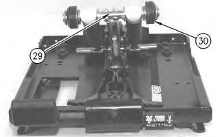
Illustration 10
g00288346
Note: Apply 5N-5561 Lubrication Compound on the roller shafts before installation.
11. Install retaining rings (32) and (36), washers (31), (33) and (35), and rollers (34). Install roller assembly (30) on each side of suspension arm (29). Make sure that the rollers do not bind.
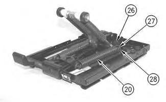
Illustration 11
g00288345
12. Install two springs (20) and plastic bearings (26) on height adjustment shaft (28). Install retaining ring (27) on each side of height adjustment shaft (28) .
This is the sample of the manual if you need complete manual click on the Download button
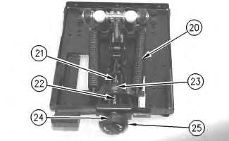
Illustration 12
g00288344
13. Install nut (23), weight adjustment screw (22), two races, the thrust bearing, weight adjustment knob (25) and pin (24). Turn weight adjustment knob (25) in the positive (+) direction in order to apply tension to springs (20). Install pin (21) in the end of weight adjustment screw (22) .
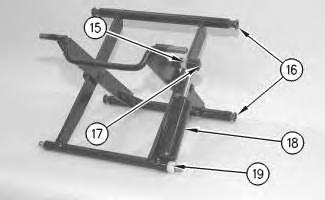
Illustration 13
g00288343
14. Install damper (18), two bearings (15) and (19), and retainer (17). Install four bearings (16) .
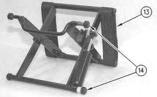
Illustration 14
g00288340
Note: Apply 5N-5561 Lubrication Compound on the roller shafts before installation.
15. Install four rollers (14) and two tether belts (13). Make sure that the rollers do not bind.
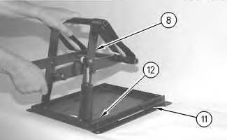
Illustration 15
g00288338
16. Install scissor assembly (8) on lower housing (11). Slide the scissor assembly into slider track (12) .
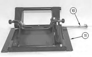
Illustration 16
g00288337
17
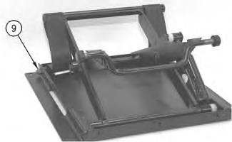
17. Install lower shaft assembly (10) in lower housing (11). Install locknut (9) on lower shaft assembly (10) .
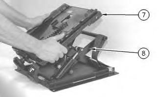
Illustration 18
g00288295
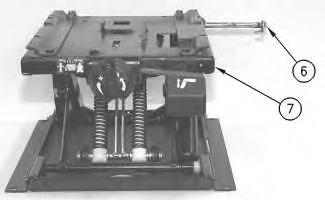
Illustration 19
g00288294
20
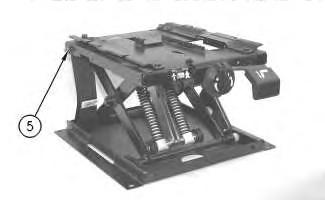
19. Install upper shaft assembly (6) in upper housing (7). Install locknut (5) .
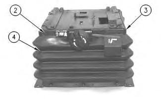
Illustration 21
g00288292
20. Remove fasteners (2). Install boot (4) and two retainers (3) .
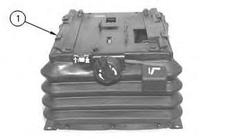
21. Install four slider blocks (1) .
Copyright 1993 - 2025 Caterpillar Inc. All Rights Reserved. Private Network For SIS Licensees.
Tue Jun 17 15:39:45 UTC+0530 2025
This is the sample of the manual if you need complete manual click on the Download button