




Product: PETROLEUM TRANSMISSION
Model: CX38-P892 PETROLEUM TRANSMISSION B4R
Configuration: CX38-P892-C18I Petroleum Power Train Package B4R00001-UP POWERED BY C18 Industrial Engine
Disassembly and Assembly
CX38–P892 Petroleum Transmission
Media Number -M0086381-00 Publication Date -01/10/2018 Date Updated -23/10/2018
Control Manifold - Assemble
SMCS - 3206-016
Assembly Procedure
i07562691
NOTICE
Keep all parts clean from contaminants.
Contaminants may cause rapid wear and shortened component life.
Note: Inspect the O-ring seals, the seals, and the gaskets. Replace the O-ring seals, the seals, and the gaskets that are worn or damaged.
Note: Lubricate O-ring seals lightly with the lubricant that is being sealed.
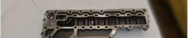

Illustration 1
Note: Lubricate the bores of valves (10) and (11) with the lubricant being sealed.
1. Install relief valve (11) and a new O-ring seal.
2. Install relief valve (10) and a new O-ring seal.
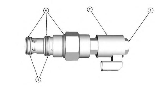
Illustration 2 g06251294
3. Install coil assembly (7) and nut (8). Tighten nut (8) to a torque of 6.1 ± 0.7 N·m (54 ± 6.0 lb in)
4. Install ring seals (9) and O-ring seals (6).
This is the sample of the manual click on the download link for complete manual
DOWNLOAD LINK
For some reason if link does not work download this pdf and then click
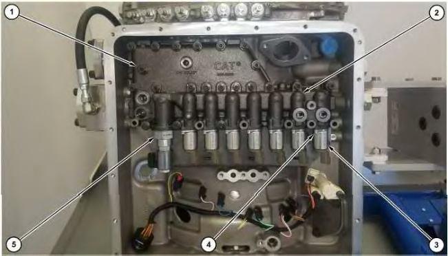
Illustration 3
Note: Lubricate the bore of main relief valve (5) with the lubricant being sealed.
5. Install main relief valve (5). Tighten main relief valve (5) to a torque of 100 ± 10 N·m (74 ± 7.0 lb ft).
Note: Lubricate the bore of transmission control valves (3) with the lubricant being sealed.
6. Install transmission control valves (3) and bolts (4). Tighten bolts (4) to a torque of 3.7 ± 0.8 N·m (33 ± 7.0 lb in).
7. Install control manifold (2) and bolts (1).
End By:
a. Install the control manifold. Refer to Disassembly and Assembly, "Control Manifold - Install".
Product: PETROLEUM TRANSMISSION
Model: CX38-P892 PETROLEUM TRANSMISSION B4R
Configuration: CX38-P892-C18I Petroleum Power Train Package B4R00001-UP POWERED BY C18 Industrial Engine
Disassembly and Assembly
CX38–P892 Petroleum Transmission
Media Number -M0086381-00 Publication Date -01/10/2018 Date Updated -23/10/2018
Control Manifold - Disassemble
SMCS - 3206-015
Disassembly Procedure
Start By:
i07562688
a. Remove the control manifold. Refer to Disassembly and Assembly, "Control Manifold - Remove".
NOTICE
Care must be taken to ensure that fluids are contained during performance of inspection, maintenance, testing, adjusting, and repair of the product. Be prepared to collect the fluid with suitable containers before opening any compartment or disassembling any component containing fluids.
Refer to Special Publication, PERJ1017, "Dealer Service Tool Catalog" for tools and supplies suitable to collect and contain fluids on Cat® products.
Dispose of all fluids according to local regulations and mandates.
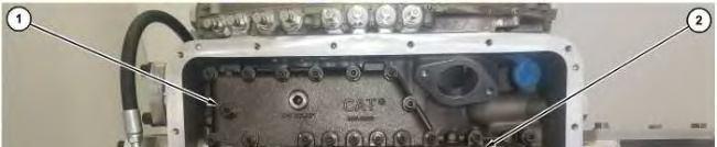
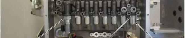

Illustration 1 g06251279
1. Remove bolts (4) and transmission control valves (3).
2. Remove main relief valve (5).
3. Remove bolts (1) and control manifold (2).
Illustration 2
4. Remove O-ring seals (6) and ring seals (9).
5. Remove nut (8) and coil assembly (7).
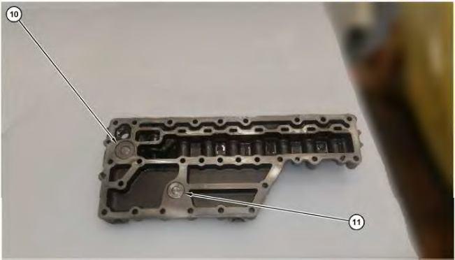
6. Reposition control manifold 180 degrees. Remove relief valve (10) and the O-ring seal.
7. Remove relief valve (11) and the O-ring seal. Copyright 1993 - 2024 Caterpillar Inc. All Rights Reserved. Private Network For SIS Licensees. Tue May 21 22:29:46 UTC+0530 2024

Product: PETROLEUM TRANSMISSION
Model: CX38-P892 PETROLEUM TRANSMISSION B4R
Configuration: CX38-P892-C18I Petroleum Power Train Package B4R00001-UP POWERED BY C18 Industrial Engine
Disassembly and Assembly
CX38–P892 Petroleum Transmission
Media Number -M0086381-00 Publication Date -01/10/2018 Date Updated -23/10/2018
i07562686
Control Manifold - Remove and Install
SMCS - 3073-010; 3206-010
Removal Procedure
Start By:
a. Remove the rear crankcase guard.
NOTICE
Care must be taken to ensure that fluids are contained during performance of inspection, maintenance, testing, adjusting, and repair of the product. Be prepared to collect the fluid with suitable containers before opening any compartment or disassembling any component containing fluids.
Refer to Special Publication, PERJ1017, "Dealer Service Tool Catalog" for tools and supplies suitable to collect and contain fluids on Cat® products.
Dispose of all fluids according to local regulations and mandates.
1. Drain the transmission into a suitable container.
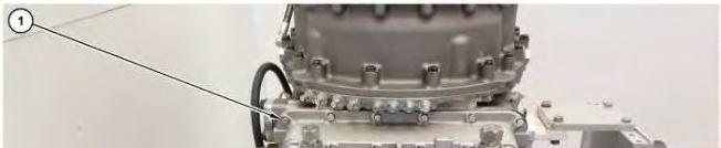
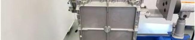

Illustration 1 g06249582
1. Remove bolts (1). Remove oil pan (2).
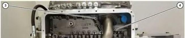
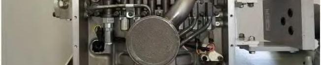

2 g06249604
2. Remove bolts (3). Remove suction tube assembly (4) and the O-ring seal.
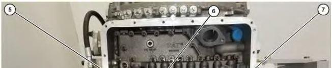
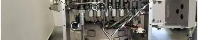

Illustration 3 g06249620
3. Remove bolt (6) and the clip.
4. Remove bolt (5) and bolt (8).
5. Remove tube (7) and the O-ring seals.
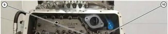
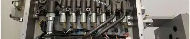

Illustration 4 g06249643
6. Remove bolts (10). Remove bolts (11).
7. Remove tube assembly (9) and the O-ring seals.
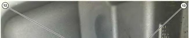
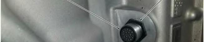

Illustration 5 g06249653
8. Remove nut (13) and push connector (12) through the housing.
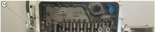
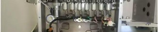

6 g06249692
9. Disconnect electrical connectors (14) and position out of the way.
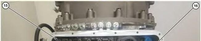
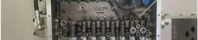

Illustration 7 g06249733
10. Remove bolts (15). Remove manifold assembly (16).
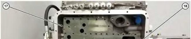
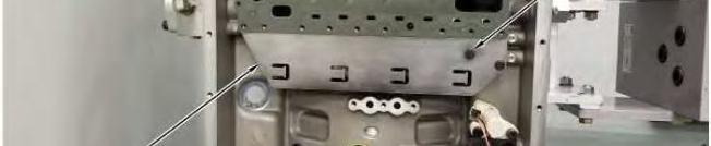

Illustration 8 g06250151
11. Remove gasket (17).
12. Remove bolts (18) and plate (19).
Installation Procedure
1. Install transmission hydraulic control manifold assembly (16) in the reverse order of removal.
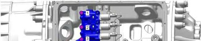
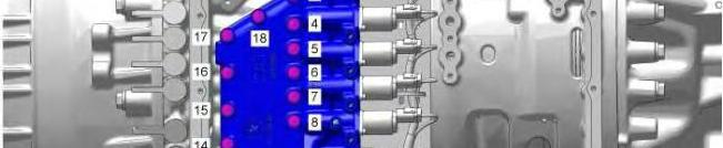

Illustration 9 g06235002
a. Position the manifold on the gasket and align with the spring pins. Install bolts (15) and tighten to a torque of 28 ± 7 N·m (248 ± 62 lb in) in the clockwise sequence shown above.
b. Lubricate the bore of tube (7) with the lubricant being sealed.
End By:
a. Install the rear crankcase guard.
Product: PETROLEUM TRANSMISSION
Model: CX38-P892 PETROLEUM TRANSMISSION B4R
Configuration: CX38-P892-C18I Petroleum
Disassembly and Assembly
CX38–P892 Petroleum Transmission Media
Gear Pump (Torque Converter and Transmission) - Assemble
Assembly Procedure
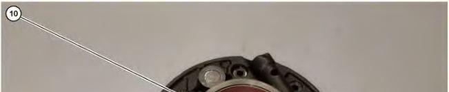


Use Tooling (A) and a suitable press to install bushing (10).


Illustration 2
2. Use Tooling (A) and a suitable press to install bushing (9) onto gears (8).
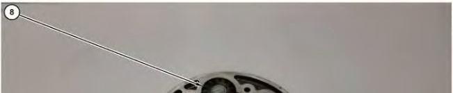


3
3. Install gears (8).


4
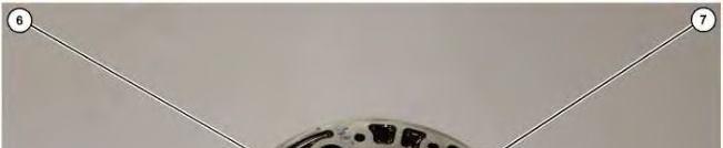
4. Use Tooling (A) and a suitable press to install bushing (7). Install oil pump gear (6).


5
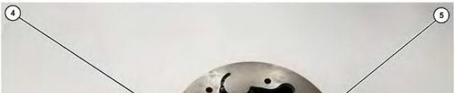
5. Reposition the pump assembly 180 degrees. Install cover (5). Install bolts (4).
Personal injury can result from being struck by parts propelled by a released spring force.
Make sure to wear all necessary protective equipment.
Follow the recommended procedure and use all recommended tooling to release the spring force.
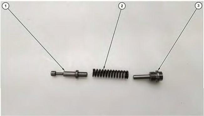
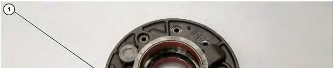


6. Install piston (1). Install spring (2). Install screw plug (3).
End By:
a. Install the transmission pump. Refer to Disassembly and Assembly, "Gear Pump (Torque Converter and Transmission) - Install". Copyright 1993 - 2024 Caterpillar Inc. All Rights Reserved. Private Network For SIS Licensees. Tue May 21 22:31:07 UTC+0530 2024
Product: PETROLEUM TRANSMISSION
Model: CX38-P892 PETROLEUM TRANSMISSION B4R
Configuration: CX38-P892-C18I Petroleum
Disassembly and Assembly
CX38–P892 Petroleum Transmission
Media Number -M0086381-00
Gear Pump (Torque Converter and Transmission) - Disassemble
SMCS - 3066-015; 3115-015; 5073-015
Disassembly Procedure
Start By:
a. Remove the transmission pump. Refer to Disassembly and Assembly, "Gear Pump (Torque Converter and Transmission) - Remove".
Personal injury can result from being struck by parts propelled by a released spring force.
Make sure to wear all necessary protective equipment.
Follow the recommended procedure and use all recommended tooling to release the spring force.
Illustration 1 g06247483
1. Remove screw plug (3). Remove spring (2) and piston (1). Note orientation for assembly purposes.
Illustration 2
2. Reposition the pump assembly 180 degrees. Remove bolts (4). Remove cover (5).
3
4
4. Remove gears (8).
5
5. Remove bushing (9) from gears (8).


6
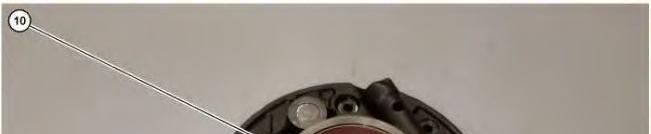
6. Reposition the pump assembly 180 degrees. Remove bushing (10).
Product: PETROLEUM TRANSMISSION
Model: CX38-P892 PETROLEUM TRANSMISSION B4R
Configuration: CX38-P892-C18I Petroleum Power Train Package B4R00001-UP POWERED BY C18 Industrial Engine
Disassembly and Assembly
CX38–P892 Petroleum Transmission
Media Number -M0086381-00 Publication Date -01/10/2018 Date Updated -23/10/2018
Gear Pump (Torque Converter and Transmission) - Install
SMCS - 3066-012; 3115-012; 5073-012
Installation Procedure NOTICE
Keep all parts clean from contaminants. Contaminants may cause rapid wear and shortened component life.
i07562804
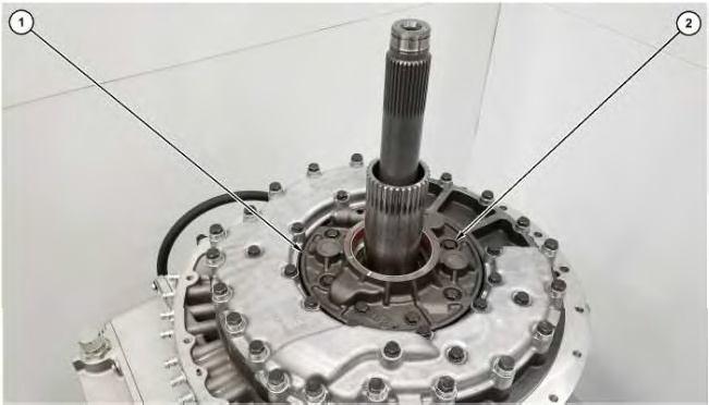
1. Install pump assembly (1).
2. Install bolts (2) and the washers.
End By:
a. Install Pump Drive.
b. Install Torque Converter.
c. Connect the transmission to the engine. Refer to Disassembly and Assembly, "Engine, Torque Converter, and Transmission - Connect".
Product: PETROLEUM TRANSMISSION
Model: CX38-P892 PETROLEUM TRANSMISSION B4R
Configuration: CX38-P892-C18I
Disassembly and Assembly
CX38–P892 Petroleum Transmission
Media Number -M0086381-00 Publication Date -01/10/2018 Date Updated -23/10/2018
Gear Pump (Torque Converter and Transmission) - Remove
SMCS - 3066-011; 3115-011; 5073-011
Removal Procedure Table 1 Required Tools Tool Part Number
Description Qty A 421-5660 Lifting Eyebolt Assembly 2
Start By:
a. Remove Torque Converter.
b. Remove Pump Drive.
NOTICE
Keep all parts clean from contaminants.
Contaminants may cause rapid wear and shortened component life.
NOTICE
Care must be taken to ensure that fluids are contained during performance of inspection, maintenance, testing, adjusting, and repair of the product. Be prepared to collect the fluid with suitable containers before opening any compartment or disassembling any component containing fluids.
i07562703
Refer to Special Publication, PERJ1017, "Dealer Service Tool Catalog" for tools and supplies suitable to collect and contain fluids on Cat® products.
Dispose of all fluids according to local regulations and mandates.


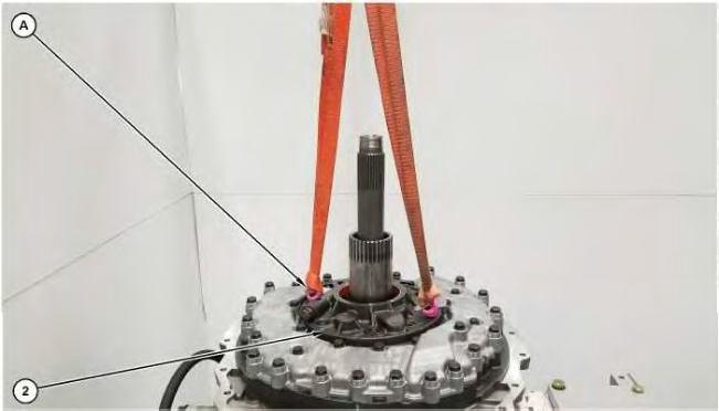
2. Attach Tooling (A) and a suitable lifting device to pump assembly (2). Remove pump assembly (2).
Copyright 1993 - 2024 Caterpillar Inc. All Rights Reserved. Private Network For SIS Licensees.
Tue May 21 22:30:35 UTC+0530 2024
This is the sample of the manual click on the download link for complete manual
DOWNLOAD LINK
For some reason if link does not work download this pdf and then click