DOWNLOAD LINK
For some reason if link does not work download this pdf and then click
Illustration 1
Personal injury can result from being struck by parts propelled by a released spring force.
Make sure to wear all necessary protective equipment.
Follow the recommended procedure and use all recommended tooling to release the spring force.
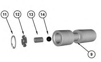
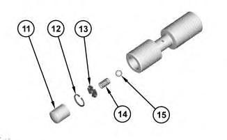
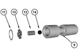
1. Install ball (14), spring (13), retainer (12), and retaining (11) into spool (9).
Illustration 2
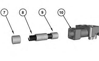
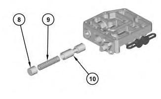
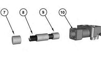
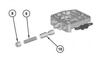
2. Install spool assembly (9), spring (8), piston (7), and O-ring seal (10).
g03717283
g03717241
3
Personal injury can result from being struck by parts propelled by a released spring force.
Make sure to wear all necessary protective equipment.
Follow the recommended procedure and use all recommended tooling to release the spring force.
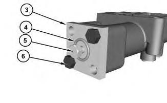
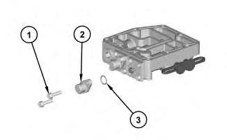
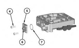
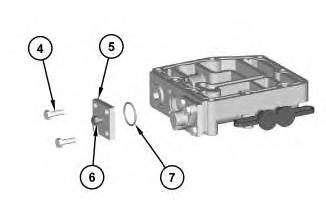
3. Install cover (3) and bolts (6). Install screw (5) and O-ring seal (4).
Illustration 4
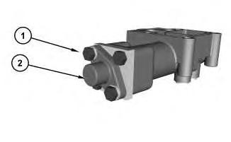
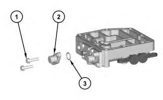
4. Install cover (2) and bolts (1).
End By:
a. Install the control manifold. Refer to Disassembly and Assembly, "Control ManifoldInstall".
Illustration
g03717219
g03717212
Product: PETROLEUM TRANSMISSION
Model: CX31-P600 PETROLEUM TRANSMISSION PFW
Configuration: CX31–P600 Well Servicing Transmission PFW00001-UP
Disassembly and Assembly
CX31-P600 Petroleum Transmission Well Servicing Media Number -KENR8152-05 Publication Date -01/09/2014 Date Updated -09/01/2019
Control Manifold - Assemble
SMCS - 3073-016; 3206-016
S/N - PDC1-UP
S/N - PDG1-UP
S/N - PDJ1-UP
S/N - PDK1-UP
S/N - PDL1-UP
S/N - PDM1-UP
S/N - PDN1-UP
S/N - PDY1-UP
S/N - PDZ1-UP
S/N - PFW1-578
S/N - PJL1-UP
Assembly Procedure (Filter Bypass Valve)
NOTICE
Keep all parts clean from contaminants.
Contaminants may cause rapid wear and shortened component life.
i03456569
Note: Inspect the O-ring seals, the seals, and the gaskets. Replace the O-ring seals, the seals, and the gaskets that are worn or damaged.
Note: Lubricate O-ring seals lightly with the lubricant that is being sealed.
1
Improper assembly of parts that are spring loaded can cause bodily injury.
To prevent possible injury, follow the established assembly procedure and wear protective equipment.
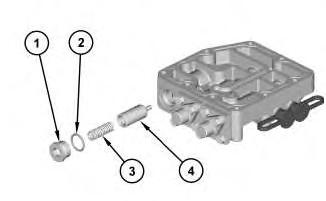
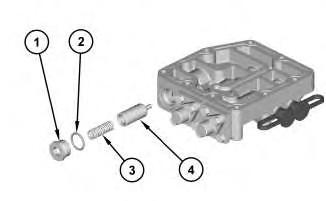
1. Install spool (4), spring (3) , O-ring seal (2), and plug (1). Tighten plug (1) to a torque of 50 ± 5 N·m (37 ± 4 lb ft).
End By:
a. Install the control manifold. Refer to Disassembly and Assembly, "Control ManifoldInstall".
Assembly Procedure (Torque Converter Outlet Relief Valve)
Table 1
Required Tools
Tool Part Number Part Description Qty A 1P-1853 Retaining Ring Pliers 1
Illustration
NOTICE
Keep all parts clean from contaminants.
Contaminants may cause rapid wear and shortened component life.
Note: Inspect the O-ring seals, the seals, and the gaskets. Replace the O-ring seals, the seals, and the gaskets that are worn or damaged.
Note: Lubricate O-ring seals lightly with the lubricant that is being sealed.
Improper assembly of parts that are spring loaded can cause bodily injury.
To prevent possible injury, follow the established assembly procedure and wear protective equipment.
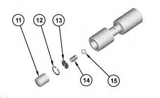
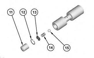
1. Install ball (15), spring (14), and retainer (13). Use Tooling (A) in order to install retaining ring (12). Install slug (11).
Illustration 2
g01801015
3
4
Improper assembly of parts that are spring loaded can cause bodily injury.
To prevent possible injury, follow the established assembly procedure and wear protective equipment.
Illustration
g01801119
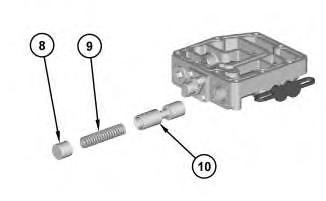
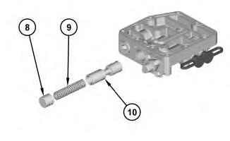
2. Install spool assembly (10), spring (9), and piston (8).
Illustration
g01801094
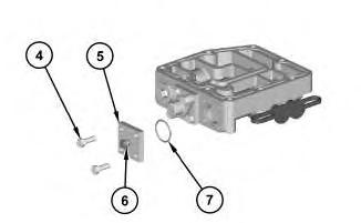
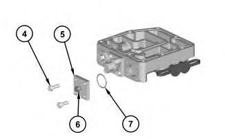
3. Install O-ring seal (7), screw (6), cover (5), and bolts (4).
5
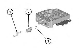
4. Install O-ring seal (3), cover (2), and bolt (1).
End By:
a. Install the control manifold. Refer to Disassembly and Assembly, "Control ManifoldInstall".
Assembly Procedure (Main Relief Valve)
Table 2
Required Tools
Tool Part Number Part Description Qty
A 1p-1853 Retaining Ring Pliers 1 NOTICE
Keep all parts clean from contaminants.
Contaminants may cause rapid wear and shortened component life.
Note: Inspect the O-ring seals, the seals, and the gaskets. Replace the O-ring seals, the seals, and the gaskets that are worn or damaged.
Note: Lubricate O-ring seals lightly with the lubricant that is being sealed.
6
Improper assembly of parts that are spring loaded can cause bodily injury.
To prevent possible injury, follow the established assembly procedure and wear protective equipment.
1. Install ball (15), spring (14), and retainer (13). Use Tooling (A ) in order to install retaining ring (12). Install slug (11).
Illustration 7
g01801001
2. Install spool assembly (10), spring (9), and piston (8).
Illustration
g01801015
Illustration 8
g01800766
Improper assembly of parts that are spring loaded can cause bodily injury.
To prevent possible injury, follow the established assembly procedure and wear protective equipment.
3. Install O-ring seal (7), screw (6), cover (5), and bolts (4).
Illustration 9
g01800757
4. Install O-ring seal (3), cover (2), and bolts (1).
End By:
a. Install the control manifold. Refer to Disassembly and Assembly, "Control ManifoldInstall".
Product: PETROLEUM TRANSMISSION
Model: CX31-P600 PETROLEUM TRANSMISSION PFW
Configuration: CX31–P600 Well Servicing Transmission PFW00001-UP
Disassembly and Assembly
CX31-P600 Petroleum Transmission Well Servicing Media Number -KENR8152-05 Publication Date -01/09/2014 Date Updated -09/01/2019
Control Manifold - Disassemble - Main Relief Valve
SMCS - 3073-015; 3206-015
S/N - GFY1-UP
S/N - PDC1-UP
S/N - PDJ1-UP
S/N - PDK1-UP
S/N - PFW579-UP
S/N - PJL1-UP
Disassembly Procedure
Start By:
a. Remove the control manifold. Refer to Disassembly and Assembly, "Control ManifoldRemove".
NOTICE
Care must be taken to ensure that fluids are contained during performance of inspection, maintenance, testing, adjusting, and repair of the product. Be prepared to collect the fluid with suitable containers before opening any compartment or disassembling any component containing fluids.
Refer to Special Publication, NENG2500, "Dealer Service Tool Catalog" for tools and supplies suitable to collect and contain fluids on Cat products.
i05902012
Dispose of all fluids according to local regulations and mandates.
Illustration 1
1. Remove bolts (1) and cover (2).
Illustration 2
g03717219
Personal injury can result from being struck by parts propelled by a released spring force.
Make sure to wear all necessary protective equipment.
Follow the recommended procedure and use all recommended tooling to release the spring force.
2. Remove screw (5) and O-ring seal (4). Remove bolts (6) and cover (3).
g03717212
3
3. Remove piston (7), spring (8), spool assembly (9), and O-ring seal (10).
Illustration 4
Personal injury can result from being struck by parts propelled by a released spring force.
Make sure to wear all necessary protective equipment.
Follow the recommended procedure and use all recommended tooling to release the spring force.
4. Remove retaining ring (11), retainer (12), spring (13), and ball (14) from spool (9).
Illustration
g03717241
g03717283
Product: PETROLEUM TRANSMISSION
Model: CX31-P600 PETROLEUM TRANSMISSION PFW
Configuration: CX31–P600 Well Servicing Transmission PFW00001-UP
Disassembly and Assembly
CX31-P600 Petroleum Transmission Well Servicing Media Number -KENR8152-05 Publication Date -01/09/2014 Date Updated -09/01/2019
Control Manifold - Disassemble
SMCS - 3073-015; 3206-015
S/N - PDC1-UP
S/N - PDG1-UP
S/N - PDJ1-UP
S/N - PDK1-UP
S/N - PDL1-UP
S/N - PDM1-UP
S/N - PDN1-UP
S/N - PDY1-UP
S/N - PDZ1-UP
S/N - PFW1-578
S/N - PJL1-UP
Disassembly Procedure (Main Relief Valve)
Table 1
Required Tools
Tool Part Number Part Description Qty A 1P-1853 Retaining Ring Pliers 1
Start By:
i03456568
a. Remove the control manifold. Refer to Disassembly and Assembly, "Control ManifoldRemove".
NOTICE
Care must be taken to ensure that fluids are contained during performance of inspection, maintenance, testing, adjusting, and repair of the product. Be prepared to collect the fluid with suitable containers before opening any compartment or disassembling any component containing fluids.
Refer to Special Publication, NENG2500, "Dealer Service Tool Catalog" for tools and supplies suitable to collect and contain fluids on Cat products.
Dispose of all fluids according to local regulations and mandates.
1
2
Illustration
g01800757
1. Remove bolts (1), cover (2), and O-ring seal (3).
Illustration
g01800766
Personal injury can result from being struck by parts propelled by a released spring force.
Make sure to wear all necessary protective equipment.
Follow the recommended procedure and use all recommended tooling to release the spring force.
2. Remove bolts (4), cover (5), screw (6), and O-ring seal (7).
Note: Mark the position of the screw for assembly purposes.
Illustration 3
3. Remove piston (8), spring (9), and spool assembly (10).
Illustration 4
g01801001
g01801015
Personal injury can result from being struck by parts propelled by a released spring force.
Make sure to wear all necessary protective equipment.
Follow the recommended procedure and use all recommended tooling to release the spring force.
4. Remove slug (11). Use Tooling (A) in order to remove retaining ring (12). Remove retainer (13), spring (14), and ball (15).
Disassembly Procedure (Torque Converter Outlet Relief Valve)
2
Pliers 1
Start By:
a. Remove the control manifold. Refer to Disassembly and Assembly, "Control ManifoldRemove".
NOTICE
Keep all parts clean from contaminants.
Contaminants may cause rapid wear and shortened component life.
NOTICE
Care must be taken to ensure that fluids are contained during performance of inspection, maintenance, testing, adjusting, and repair of the product. Be prepared to collect the fluid with suitable containers before opening any compartment or disassembling any component containing fluids.
Refer to Special Publication, NENG2500, "Dealer Service Tool Catalog" for tools and supplies suitable to collect and contain fluids on Cat products.
Dispose of all fluids according to local regulations and mandates.
Illustration 5
1. Remove bolts (1), cover (2), and O-ring seal (3).
Illustration 6
Personal injury can result from being struck by parts propelled by a released spring force.
Make sure to wear all necessary protective equipment.
Follow the recommended procedure and use all recommended tooling to release the spring force.
g01801053
g01801094
2. Remove bolts (4), cover (5), screw (6), and O-ring seal (7).
Note: Mark the position of the screw for assembly purposes.
Illustration 7
g01801119
3. Remove piston (8), spring (9), and spool assembly (10).
Illustration 8
g01801015
Personal injury can result from being struck by parts propelled by a released spring force.
Make sure to wear all necessary protective equipment.
Follow the recommended procedure and use all recommended tooling to release the spring force.
4. Remove slug (11). Use Tooling (A) in order to remove retaining ring (12). Remove retainer (13), spring (14), and ball (15).
Disassembly Procedure (Filter Bypass Valve)
Start By:
a. Remove the control manifold. Refer to Disassembly and Assembly, "Control ManifoldRemove".
NOTICE
Keep all parts clean from contaminants.
Contaminants may cause rapid wear and shortened component life.
NOTICE
Care must be taken to ensure that fluids are contained during performance of inspection, maintenance, testing, adjusting, and repair of the product. Be prepared to collect the fluid with suitable containers before opening any compartment or disassembling any component containing fluids.
Refer to Special Publication, NENG2500, "Dealer Service Tool Catalog" for tools and supplies suitable to collect and contain fluids on Cat products.
Dispose of all fluids according to local regulations and mandates.
Personal injury can result from being struck by parts propelled by a released spring force.
Make sure to wear all necessary protective equipment.
Follow the recommended procedure and use all recommended tooling to release the spring force.
1. Remove plug (1), O-ring seal (2), spring (3), and spool (4). Copyright 1993 - 2024 Caterpillar Inc.
Rights Reserved.
Network For SIS Licensees.
Product: PETROLEUM TRANSMISSION
Model: CX31-P600 PETROLEUM TRANSMISSION PFW
Configuration: CX31–P600 Well Servicing Transmission PFW00001-UP
Disassembly and Assembly
CX31-P600 Petroleum Transmission Well Servicing Media Number -KENR8152-05 Publication Date -01/09/2014 Date Updated -09/01/2019
Control Manifold - Install
SMCS - 3073-012; 3206-012
S/N - GFY1-UP
S/N - PDC1-UP
S/N - PDJ1-UP
S/N - PDK1-UP
S/N - PFW579-UP
S/N - PJL1-UP
Installation Procedure
NOTICE
Keep all parts clean from contaminants.
Contaminants may cause rapid wear and shortened component life.
Note: Inspect the O-ring seals, the seals, and the gaskets. Replace the O-ring seals, the seals, and the gaskets that are worn or damaged.
Note: Lubricate O-ring seals lightly with the lubricant that is being sealed.
i05901908
Illustration 1
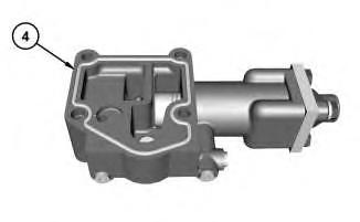
1. Install O-ring seal (4).
g03717135
Illustration 2
g03717119
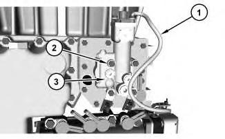
2. Install control manifold (3) and bolts (2). Tighten bolts (2) to a torque of 30 ± 4 N·m (266 ± 35 lb in).
3. Connect harness assembly (1).
Copyright 1993 - 2024 Caterpillar Inc. All Rights Reserved. Private Network For SIS Licensees. Sat Nov 30 09:54:07 UTC+0530 2024
This is the sample of the manual click on the download link for complete manual