

Note: Use Bookmarks panel to navigate

Product: VIBRATORY COMPACTOR
Model: CS78B VIBRATORY COMPACTOR M78
Configuration: CS78B, CS79B Vibratory Soil Compactor M7800001-UP (MACHINE) POWERED BY C7.1 Engine
Disassembly and Assembly
CP74B, CS74B, CP76B, CS76B, CS78B and CS79B Vibratory Soil Compactors Machine Systems Media Number -UENR0166-10
Articulating and Oscillating Hitch - Assemble
SMCS - 7057-016; 7113-016
Assembly Procedure
Table 1
Required Tools
B 6V-3135 Spanner Wrench 1
C 5P-3931 Anti-Seize Compound 1
D 1P-0808 Multipurpose Grease 1
E 9S-3263 Thread Lock Compound 1
F 3B-8489 Grease Fitting 2
1
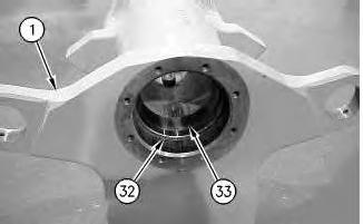
1. Lower the temperature of bearing cups (33). Install inner bearing cup (33) and spacer (32) in both sides of hitch (1).
2
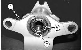
2. Install bearing cones (30) and bearing cup (31) in the upper side of hitch (1).
3
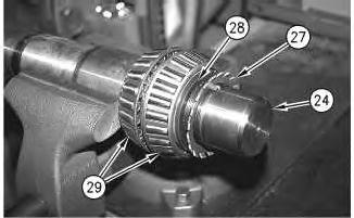
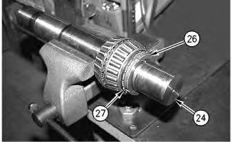
3. Install bearing cones (29), spacer (28), and lock washer (27) on shaft (24).
4
4. Apply Tooling (C) on the face and on the threads of nut (26). Install nut (26) on shaft (24). Use Tooling (B) to tighten the nut to a torque of 813 ± 136 N·m (600 ± 100 lb ft).
5. Align a tab of lock washer (27) with a slot in nut (26). Bend the tab of lock washer (27) into the slot.
5
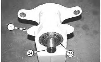
6. Position shaft (24) in hitch (1) and install bearing cup (25).
6
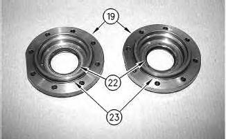
7. Install lip seals (22) in bearing caps (19). Apply Tooling (D) on the sealing lip.
8. Install O-ring seals (23) on bearing caps (19). Apply Tooling (D) on the O-ring seals.
7
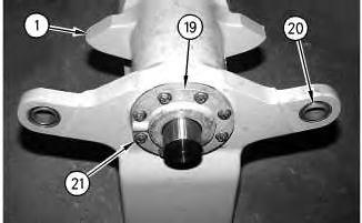
Note: After bearing cap (19) and bolts (21) are installed on both sides of hitch (1) there may be a gap between the bearing cap and the hitch.
9. Apply Tooling (E) on the threads of bolts (21). Install bearing cap (19) and bolts (21) on both sides of hitch (1).
10. Install bearings (20) in hitch (1).
8
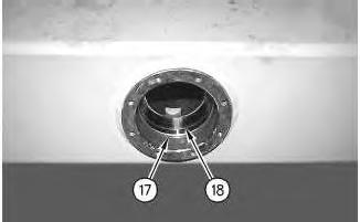
11. Lower the temperature of bearing cups (18). Install bearing cup (18) and spacer (17) in both sides of the yoke.
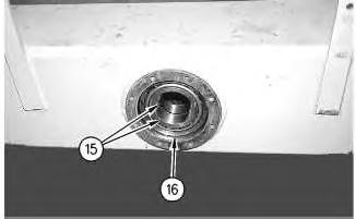
Illustration 9
12. Install bearing cones (15) and bearing cup (16) in the yoke.
10
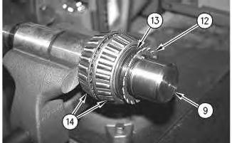
13. Install bearing cones (14), spacer (13), and lock washer (12) on shaft (9).
11
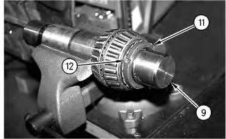
14. Apply Tooling (C) on the face and on the threads of nut (11). Install nut (11) on shaft (9). Use Tooling (B) to tighten the nut to a torque of 813 ± 136 N·m (600 ± 100 lb ft).
15. Align a tab of lock washer (12) with a slot in nut (11). Bend the tab of lock washer (12) into the slot.
12
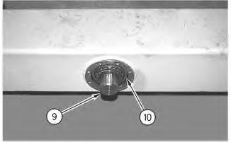
16. Position shaft (9) in the yoke and install bearing cup (10).
13
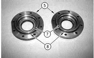
17. Install lip seals (7) in bearing caps (5). Apply Tooling (D) on the sealing lip.
18. Install O-ring seals (8) on bearing caps (5). Apply Tooling (D) on the O-ring seals.
14
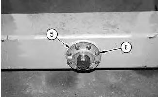
Note: After bearing cap (5) and bolts (6) are installed on both sides of the yoke there may be a gap between the bearing cap and the hitch.
19. Apply Tooling (E) on the threads of bolts (6). Install bearing cap (5) and bolts (6) on both sides of the yoke.
15
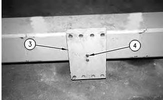
20. Use a suitable lifting device to position end plate (3) on the shaft. The weight of the end plate is approximately 38 kg (84 lb). Install bolts (4).
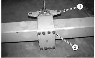
Illustration 16
21. Use a suitable lifting device to position hitch (1) on the yoke. The weight of the hitch is approximately 150 kg (331 lb). Install bolts (2). Remove the suitable lifting device.
17
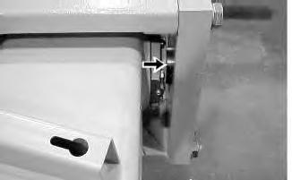
Illustration 18
Note: Use the following procedure to fill the cavities in the articulating and oscillating hitch with grease.
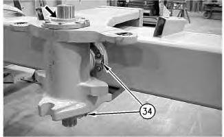
22. Remove plugs (34) and install Tooling (F).
23. Fill the cavities with Tooling (D) until the grease can be seen at bearing caps.
24. Remove Tooling (F) and install plugs (34).
End By:
a. Install the articulating and oscillating hitch. Refer to Disassembly and Assembly, "Articulating and Oscillating Hitch - Install".
Product: VIBRATORY COMPACTOR
Model: CS78B VIBRATORY COMPACTOR M78
Configuration: CS78B, CS79B Vibratory Soil Compactor M7800001-UP (MACHINE) POWERED BY C7.1 Engine
Disassembly and Assembly
CP74B, CS74B, CP76B, CS76B, CS78B and CS79B Vibratory Soil Compactors Machine Systems Media Number -UENR0166-10
Articulating and Oscillating Hitch - Disassemble
SMCS - 7057-015; 7113-015
Disassembly Procedure
Table 1
Required Tools Tool
8B-7548 Push-Puller 1
4C-5653 Threaded Adapter 2
B 6V-3135 Spanner Wrench 1
Start By:
a. Remove the articulating and oscillating hitch. Refer to Disassembly and Assembly, "Articulating and Oscillating Hitch - Remove".
1
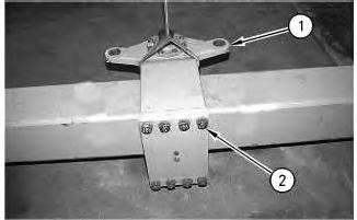
1. Attach a lifting sling and a suitable lifting device to hitch (1), as shown.
2. Remove bolts (2) and remove hitch (1) from the yoke. The weight of the hitch is approximately 150 kg (331 lb).
2
3. Attach a suitable lifting device to end plate (3). Remove bolts (4) and remove end plate (3) from the shaft. The weight of the end plate is approximately 38 kg (84 lb).
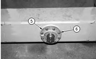
Illustration 3
4. Remove bolts (6) and bearing cap (5) from both sides of the yoke.
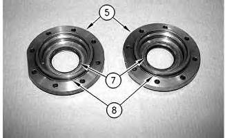
Illustration 4
5. Remove lip seals (7) from bearing caps (5).
6. Remove O-ring seals (8) from bearing caps (5).
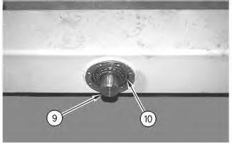
Illustration 5
7. Install Tooling (A) on the yoke. Use Tooling (A) to remove shaft (9) and bearing cup (10) from the yoke.
6
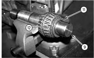
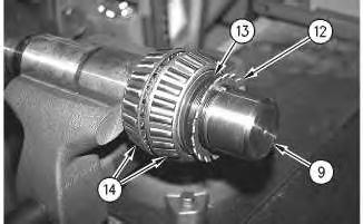
8. Bend the tab of lock washer (12) from the slot in nut (11).
9. Use Tooling (B) to remove nut (11) from shaft (9).
7
10. Remove lock washer (12), spacer (13) and bearing cones (14) from shaft (9).
8
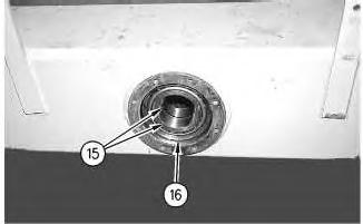
11. Remove bearing cup (16) and bearing cones (15) from the yoke.
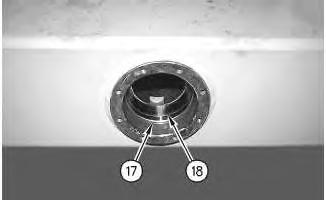
12. Remove spacer (17) and bearing cup (18) from both sides of the yoke.
10
13. Remove bearings (20) from hitch (1).
14. Remove bolts (21) and bearing cap (19) from both sides of hitch (1).
Illustration 11
15. Remove lip seals (22) from bearing caps (19).
16. Remove O-ring seals (23) from bearing caps (19).
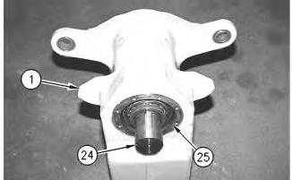
Illustration 12
17. Install Tooling (A) on hitch (1). Use Tooling (A) to remove shaft (24) and bearing cup (25) from the lower side of the hitch.
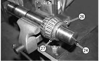
Illustration 13
18. Bend the tab of lock washer (27) from the slot in nut (26).
19. Use Tooling (B) to remove nut (26) from shaft (24).
Illustration 14
20. Remove lock washer (27), spacer (28) and bearing cones (29) from shaft (24).
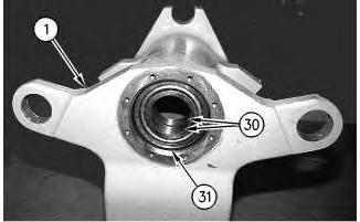
Illustration 15
g00815731
21. Remove bearing cup (31) and bearing cones (30) from the upper side of hitch (1).

Illustration 16
g00816739
22. Remove spacer (32) and inner bearing cup (33) from both sides of hitch (1).
Copyright 1993 - 2024 Caterpillar Inc.
Product: VIBRATORY COMPACTOR
Model: CS78B VIBRATORY COMPACTOR M78
Configuration: CS78B, CS79B Vibratory Soil Compactor M7800001-UP (MACHINE) POWERED BY C7.1 Engine
Disassembly and Assembly
CP74B, CS74B, CP76B, CS76B, CS78B and CS79B Vibratory Soil Compactors Machine Systems Media
Articulating and Oscillating Hitch - Remove and Install
SMCS - 7057-010; 7113-010
Removal Procedure
Table 1 Required Tools
Start By: a. Remove the drum.
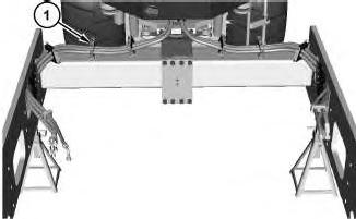
Illustration 1
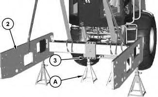
Illustration 2 g02745700
1. Remove clamps (1).
2. Install Tooling (A), as shown. Attach a suitable lifting device to yoke assembly (2). The weight of yoke assembly (2) is approximately 4400 kg (9700 lb). Remove bolts (3). Remove yoke assembly (2). Place yoke assembly (2) on suitable cribbing.
Installation Procedure
1. Install yoke assembly (2) in the reverse order of removal. Copyright 1993 - 2024 Caterpillar Inc. All Rights Reserved.

Product: VIBRATORY COMPACTOR
Model: CS78B VIBRATORY COMPACTOR M78
Configuration: CS78B, CS79B Vibratory Soil Compactor M7800001-UP (MACHINE) POWERED BY C7.1 Engine
Disassembly and Assembly
CP74B, CS74B, CP76B, CS76B, CS78B and CS79B Vibratory Soil Compactors Machine Systems
Axle - Install
SMCS - 3013-012; 3260-012; 3278-012; 3282-012
Installation Procedure
1
1. Position axle (1) using Tooling (B). Illustration 1
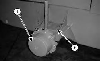
2. Attach a suitable lifting device and Tooling (A) to axle (1). Install axle (1) and install bolts (3) on both sides of the axle. The weight of the axle is approximately 470 kg (1036 lb).
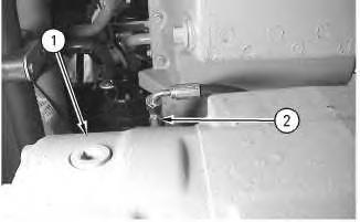
Illustration 2 g00984959
3. If the axle is equipped with brakes, connect fitting (2) on axle (1).
End By:
a. Install the wheel and the tire.
b. Install the axle propel motor.
Copyright 1993 - 2024 Caterpillar Inc. All Rights Reserved. Private Network For SIS Licensees. Thu Jul 11 16:24:17 UTC+0530 2024
Product: VIBRATORY COMPACTOR
Model: CS78B VIBRATORY COMPACTOR M78
Configuration: CS78B, CS79B Vibratory Soil Compactor M7800001-UP (MACHINE) POWERED BY C7.1 Engine
Disassembly and Assembly
CP74B, CS74B, CP76B, CS76B, CS78B and CS79B Vibratory Soil Compactors Machine Systems
Axle - Remove
SMCS - 3013-011; 3260-011; 3278-011; 3282-011
Removal Procedure
1
Start By:
a. Remove the axle propel motor.
b. Remove the wheel and the tire.
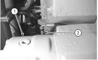
Illustration 1 g00984959
1. If the axle is equipped with brakes, disconnect fitting (2) from axle (1).
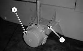
Illustration 2 g01012121
2. Attach a suitable lifting device and Tooling (A) to axle (1), as shown.
3. Remove bolts (3) from both sides of axle (1).
4. Lower axle (1) to Tooling (B) and remove axle (1) from the machine. The weight of axle (1) is approximately 470 kg (1036 lb). Copyright 1993 - 2024 Caterpillar Inc.
Product: VIBRATORY COMPACTOR
Model: CS78B VIBRATORY COMPACTOR M78
Configuration: CS78B, CS79B Vibratory Soil Compactor M7800001-UP (MACHINE) POWERED BY C7.1 Engine
Disassembly and Assembly
CP74B, CS74B, CP76B, CS76B, CS78B and CS79B Vibratory Soil Compactors Machine Systems
Media Number -UENR0166-10 Publication Date -01/01/2015 Date Updated -01/10/2018
Axle Guard - Remove and Install
SMCS - 7185-010
Removal Procedure
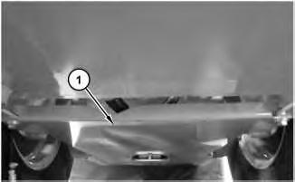
1
i04592514
1. Attach a suitable lifting device to guard (1). The weight of guard (1) is approximately 21 kg (47 lb). Remove guard (1).
Installation Procedure
1. Install guard (1) in the reverse order of removal.
Copyright 1993 - 2024 Caterpillar Inc. All Rights Reserved. Private Network For SIS Licensees.
Thu Jul 11 16:23:36 UTC+0530 2024