Product: VIBRATORY COMPACTOR
Model: CS78B VIBRATORY COMPACTOR M78
Configuration: CS78B, CS79B Vibratory Soil Compactor M7800001-UP (MACHINE) POWERED BY C7.1 Engine
Operation and Maintenance Manual
Cat® Grade Control for Soil Compactors
Foreword
SMCS - 7008; 7600-ZM
Literature Information
This manual should be stored in the literature holder.
This manual contains safety information, operation instructions, and maintenance recommendations.
s00514343
Some photographs or illustrations in this publication show details or attachments that can be different from your product.
Continuing improvement and advancement of product design might have caused changes to your product which are not included in this publication. Read, study and keep this manual with the product.
Whenever a question arises regarding your product, or this publication, please consult your Cat dealer for the latest available information.
Safety
The safety section lists basic safety precautions. In addition, this section identifies the text and locations of warning signs and labels used on the product.
Operation
The operation section is a reference for the new operator and a refresher for the experienced operator. This section includes a discussion of gauges, switches, product controls, attachment controls, and programming information.
Photographs and illustrations guide the operator through correct procedures of checking, starting, operating and stopping the product.
Operating techniques outlined in this publication are basic. Skill and techniques develop as the operator gains knowledge of the product and its capabilities.
Maintenance
The maintenance section is a guide to equipment care.
Copyright 1993 - 2024 Caterpillar Inc. All Rights Reserved. Private Network For SIS Licensees. Thu Jul 11 16:35:44 UTC+0530 2024
Product: VIBRATORY COMPACTOR
Model: CS78B VIBRATORY COMPACTOR M78
Configuration: CS78B, CS79B Vibratory Soil Compactor M7800001-UP (MACHINE) POWERED BY C7.1 Engine
Operation and Maintenance Manual
Cat® Grade Control for Soil Compactors
Safety Messages
SMCS - 7405
Do not operate or work on this machine unless you have read and understand the instructions and warnings in the Operation and Maintenance Manuals. Failure to follow the instructions or heed the warnings could result in injury or death. Contact your Caterpillar dealer for replacement manuals. Proper care is your responsibility.
In order to prevent personal injury during installation and removal of the GPS receiver, use an approved access system in order to reach the mounting location of the GPS receiver on top of the cab.
Crushing Prevention and Cutting Prevention
Support the equipment properly when you work beneath the equipment. Do not depend on the hydraulic cylinders to hold up the equipment. An attachment can fall if a control is moved, or if hydraulic lines break.
Unless you are instructed otherwise, never attempt adjustments while the machine is moving. Also, never attempt adjustments while the engine is running.
i04806000
Whenever there are attachment control linkages, the clearance in the linkage area will increase or the clearance in the linkage area will decrease with movement of the attachment. Stay clear of all rotating and moving parts.
Keep objects away from moving fan blades. The fan blade will throw objects or cut objects. Do not use a kinked wire cable or a frayed wire cable.
Wear gloves when you handle wire cable. When you strike a retainer pin with force, the retainer pin can fly out. The loose retainer pin can injure personnel. Make sure that the area is clear of people when you strike a retainer pin.
In order to avoid injury to your eyes, Wear protective glasses when you strike a retainer pin.
Chips or other debris can fly off objects when you strike the objects. Make sure that no one can be injured by flying debris before striking any object.
Operation
Clear all personnel from the machine and from the area.
Clear all obstacles from the path of the machine. Beware of hazards (wires, ditches, and so on).
Be sure that all windows are clean.
Secure the doors and the windows in the open position or in the shut position.
Adjust the rear mirrors (if equipped) for the best visibility close to the machine.
Make sure that the horn, the travel alarm (if equipped), and all other warning devices are working properly.
Fasten the seat belt securely.
Warm up the engine and the hydraulic oil before operating the machine.
Only operate the machine while you are in a seat. The seat belt must be fastened while you operate the machine. Only operate the controls while the engine is running.
While you operate the machine slowly in an open area, check for proper operation of all controls and all protective devices. Before you move the machine, make sure that no one will be endangered.
Do not allow riders on the machine unless the machine has the following equipment:
• Additional seat
• Additional seat belt
• Rollover Protective Structure (ROPS)
Note any needed repairs during machine operation. Report any needed repairs.
Avoid any conditions that can lead to tipping the machine. The machine can tip when you work on hills, on banks and on slopes. Also, the machine can tip when you cross ditches, ridges, or other unexpected obstructions.
Avoid operating the machine across the slope. When possible, operate the machine up the slopes and down the slopes.
Maintain control of the machine.
Do not overload the machine beyond the machine capacity.
Be sure that the hitches and the towing devices are adequate.
Never straddle a wire cable. Never allow other personnel to straddle a wire cable.
Before you maneuver the machine, make sure that no personnel are between the machine and the trailing equipment.
Always keep the Rollover Protective Structure (ROPS) installed during machine operation.
Monitor the location of components that are mounted to the drum. Ensure that the components do not come into contact with other parts of the machine during operation. Copyright 1993 - 2024 Caterpillar Inc.
Network For SIS Licensees. Thu Jul 11 16:35:54 UTC+0530 2024
Product: VIBRATORY COMPACTOR
Model: CS78B VIBRATORY COMPACTOR M78
Configuration: CS78B, CS79B Vibratory Soil Compactor M7800001-UP (MACHINE) POWERED BY C7.1 Engine
Operation and Maintenance Manual
Cat® Grade Control for Soil Compactors
Display Description
SMCS - 7490
Introduction
i06838218
The display is a computer that runs the firmware for the Cat® Compaction Control. This section describes the operation of the display.
Working with the Display
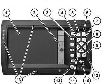
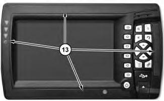
The display is used to operate the Cat Compaction Control. The CB460 and CB450 has a color LCD screen to display guidance and push-button controls to operate the system. The display contains internal light bars and a USB flash drive port. The USB flash drive is for loading and saving machine and display configuration data, and for loading and saving profiles and models. Refer to Illustration 1.
Illustration 1 g02284653
CB460 display
(1) LCD
(2) Soft key labels
(3) Soft keys
(4) "Next" key
(5) Zoom in
(6) Zoom out
(7) Escape key
(8) Arrow keys
(9) "OK" key
(10) USB port
(11) Menu key
(12) Power button
(13) Light bars
Soft Keys
The soft keys (3) are the six physical keys that are located immediately beside the LCD. Soft keys (3) are used in order to operate the function shown on the soft key label located to the left of the soft key.
Soft Key Labels
The soft key labels (2) are graphical keys that appear at the right side of the screen. In order to activate the displayed function, press the soft key that is directly beside the soft key label. For example, in order to change the drum focus, press the soft key that is located directly beside the soft key label that contains the "Drum: Left", and "Drum: Right" icons.
Soft key functions relate to the particular screens or dialogs. These functions are only available when these screens or dialogs are accessed. For example, "New Level" only appears on the "Design Selection" screen, as that function relates only to that screen.
If a soft key has no function in a screen or a dialog, the label for the soft key is blank.
The icon on a soft key label can show one of the following icon details:
• A description of the operation that is performed is shown when the soft key is pressed once.
• The setting that is selected. The icon on the soft key label changes when you press the soft key to switch between options. For example, the soft key icons "Drum:Left" and "Drum:Right" show the side of the drum selected for horizontal guidance on threedimensional systems. The current end (Left or Right) shows on the icon.
Some soft key labels (2) will appear in more than one dialog. The function of the soft key is the same function as the other dialogs.
Guidance Soft Key Icon Descriptions
GPS - This soft key allows the operator to change the "GPS Accuracy Mode" of "Fine", "Medium", or "Course".
Direction: Forward - Direction of motion is calculated to be forwards. Press to open the direction dialog.
Direction: Reverse - Direction of motion is calculated to be in reverse. Press to open the direction dialog.
Record Point - Record a point, when point recording active.
Map Recording Soft Key Descriptions
Reset Map - Press the reset map icon to open the "Reset Map" dialog. By default, this softkey is only displayed in manager mode for all machine types except compactors.
Note: Compactors require you to reset the map manually. Enter "Mapping / Recording" in the setup menu to reset the map.
Mapping: Auto - Map data is recorded when the machine is considered to be working, for example when a compactors drum is vibrating. Press to change map recording to the On mode.
Mapping: Off - Map data is not recording. Press to change map recording to the Auto mode.
Mapping: On - Map data is recording continuously. Press to stop recording map data.
Soil Compactor Soft Key Icons
Drum: Left - Focus is on the left side of the drum. Press to change focus to the right side of the drum.
Drum: Right - Focus is on the right side of the drum. Press to change focus to the left side of the drum.
Horizontal Offset - Press to open "Horizontal Offset" dialog.
Vertical Offset - Press to open "Verticle Offset" dialog.
Proofing: Off - Proofing run data is not recording. Press to start recording proofing run data.
Proofing: On - Proofing run data is recording. Press to stop recording proofing run data, and to open the "Proofing Run Summary" dialog.
Power Key
The power key (12) has the following functions:
• Turn on the display.
• Turn off the display.
In order to turn on the control box, press the power key. After a brief pause, an opening screen appears.
Note: If the system detects upgrade files, other system files, or that the operating system is out of date, contact your supervisor immediately.
In order to turn off the display, press and hold the power key (12) for several seconds, until the display shuts down. This delay reduces the risk of inadvertently shutting off the power. You can turn off the Cat® Compaction Control system from any screen or from any dialog.
Menu Key
Pressing menu key (11) will display the "Setup Menu" on the display.
Escape Key
The Escape key (7) allows the operator to exit from a dialog without saving changes, or allows the operator to exit from a menu.
"OK" Key
"OK" key (9) allows the operator to save changes that are made in a dialog, and allows the operator to exit the dialog.
Next Key
Next key (4) displays the next guidance screen. Additionally, the next key selects the next field in a dialog.
Arrow Keys
Use arrow keys (8) to perform the following actions:
• Move within menus and lists.
• Enter text or numbers into data entry fields in dialogs.
• Pan the "Plan view", pan the "Cross section view", or pan the "Profile view".
Navigating within menus and lists
In order to choose an item from a menu or a list, complete the following steps:
1. Press the arrow keys in order to highlight the desired option.
2. Press "OK" key (9).
Entering data
In text and number fields in any of the dialogs, complete the following actions:
• Press the up arrow or the down arrow in order to scroll through the available characters.
• Press the left arrow or the right arrow in order to move between characters.
Panning around the screen
Press arrow keys (8) to control the position of the "Plan View" screen, "Cross Section View" screen, or the "Profile View" screen:
• Press the right arrow in order to move the view to the right.
• Press the left arrow in order to move the view to the left.
• Press the up arrow in order to move the viewup.
• Press the down arrow in order to move the view down.
Zoom In Key
Zoom in key (5) is used to zoom in the current view. When you zoom in, you see more detail on the screen. As you zoom in, less of the design and linework are shown. You can zoom in until the drum fills the screen.
Holding down on zoom in key (5) allows the operator to zoom to the machine. Zooming to the machine will resize the current view around the machine symbol. This feature is only available in the "Plan View" and "Cross-Section View" when a design is loaded. In "Plan View", zooming the machine will display five drum-widths around the machine. In "Cross-Section View", zooming to the machine will display two drum-widths on either side of the machine.
Zoom Out Key
Zoom out key (6) is used to zoom out the current view. When you zoom out, you see less detail on the screen. As you zoom out, more of the design and linework are shown. You can`zoom out so far that the machine is barely visible on the screen. When you zoom out to this degree, the machine symbol is no longer drawn to scale. Keeping the machine symbol large makes sure that you can always see the machine symbol in the current view.
Holding down on the zoom out key allows the operator to zoom to the whole design. This feature is only available in the plan view and cross-section View when a design is loaded.
Display Brightness
The display brightness can be adjusted by holding the menu key and pressing the zoom in key or the zoom out key.
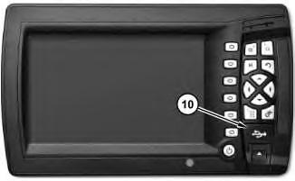
USB Port
Illustration 2
(10) USB port
g02286034
USB port (10) allows the user to perform the following tasks:
• Load design data from the USB to the system
• Save design data from the system to the USB
• Save display data from the system to the USB
Note: The USB port is only intended for uploading and downloading data files from a flash drive.
USB Port and Data Storage
Files and data are stored on the control box in an area known as system memory. The files and data in system memory are used by the system and there is only limited site supervisor access via the control box.
To access the files and data in system memory, transfer the files from the control box onto a USB flash drive. The files and data on the USB flash drive can be directly accessed from a laptop or an office computer.
Note: When you insert a USB flash drive into the control box, system operation is temporarily disabled. System operation resumes when the USB flash drive is removed.
The USB flash drive folder structure is:
• At the root directory level is a "Machine Control Data" folder.
• Within the "Machine Control Data" folder are machine-specific folders based on machines names, which contain machine-specific data. For example, a "SC" folder for soil compactor.
Note: The system will create folders if folders do not exist when files are transferred to the USB flash drive.
To insert a USB flash drive, complete the following steps:
Note: Use a USB flash drive with a metal surround
1. Lift the USB port door with the end of the USB drive.
2. Insert a USB flash drive.
To transfer data to and from the control box and the USB flash drive:
1. Start the control box.
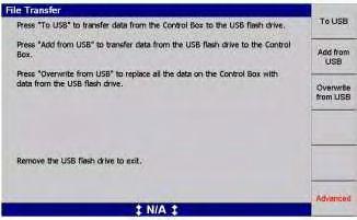
Illustration 3
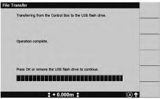
2. Insert the USB flash drive into the control box USB port. The file transfer dialog appears as shown in Illustration 3.
To transfer files from the control box to the USB flash drive:
1. Press "To USB" softkey. Data on the control box transfers to the "Machine Control Data" folder on the USB flash drive and is written to the machine subfolder. The machine subfolder name is the same as the machine name set on the control box.
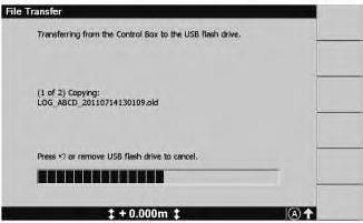
Illustration 4
2. A progress bar appears, showing the progress of the data transfer as shown in Illustration 4. To exit to the previous menu, press "Ok" or remove the USB flash drive from the USB port on the control box.
To transfer from the USB flash drive to the control box:
1. Press "Add from USB" or "Overwrite from USB" softkey. Data in the "Machine Control Data/Machine Name" folder and subfolders, and the "Machine Control Data/All" folder of the USB flash drive transfers to the control box.
g02323715
g02323795
5
2. A progress bar appears, showing the progress of the data transfer as shown in Illustration 5. To exit to the previous menu, press "OK" or remove the USB flash drive from the USB port on the control box.
If more space is needed on the display, contact your site supervisor to delete some unneeded files.
Working with Dialogs
The "system setup", "alignment selection", "horizontal offset" selection, "vertical offset" selection, "design selection", and the "Setup Menu - Configuration" option screens are called dialogs. Use dialogs in order to enter data. Use the dialogs in order for the Cat® Compaction Control system to be set up according to your requirements. The selected field in a dialog is identified by the blue background color.
Press the next key (4) on the display in order to move to different fields within the dialogs.
Press the arrow keys (8) on the display in order to enter data:
The up arrow steps through the upper case letters "A through Z", the numbers "0 through 9", the decimal point ".", the negative sign "–", the positive sign "+", a space , and back to "A".
Note: Available values will depend on the type of field that is selected. For example, the only values that are available for number fields are 0 through 9, the decimal point ".", "–", and "+".
The down arrow steps through the same character set, but in reverse.
When you change a character in a field, the up arrow and the down arrow start stepping from the existing character.
The right arrow steps to the next character to the right. In fields that allow spaces, press the right arrow twice in order to insert a space.
The left arrow is used in order to move back one character to the left. This move deletes the character in the space to the left.
Dialogs may contain any of the following items:
Text fields - Use the text fields in order to enter your own information. For example, when you set up the name of your level surface design or sloping surface design, use arrow keys (8) to enter this data.
Number fields - Use the number fields in order to enter required values. For example, when you set up the vertical and horizontal offset, use arrow keys (8) in order to enter values into these fields.
List boxes - Lists options or possible selections. Use arrow keys (8) in order to select the listed item.
"No GPS Receiver Data"
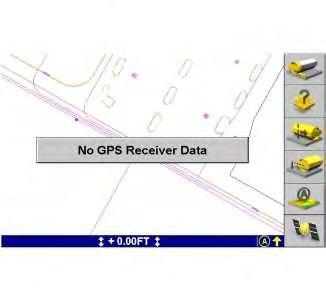
An error such as "No GPS Receiver Data" will cause inaccurate guidance. When an error occurs, a message flashes on the screen. Guidance is not provided under these conditions. For more information, Refer to Operation and Maintenance Manual, "Flashing Messages". Illustration 6 is an example of a warning message.
6 g03042159 No GPS receiver data message.
The "No GPS Receiver Data" warning appears when the receiver has stopped outputting data for at least 1.5 seconds.
Hourglass
When the system performs an operation that takes more than a few seconds, an hourglass appears on the current screen. For example, the hourglass appears in the following situations:
• The hourglass appears in the "Plan View", the "Cross Section View", or the "Profile View", while the software updates the display after a pan or zoom.
Illustration
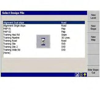
• The hourglass will appear in the "Select Design File" dialog while a design is being loaded from the internal memory.
The following dialog shows the hourglass while the Cat Compaction Control system loads a design file:
Illustration 7
Guidance Status Bar
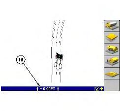
Illustration 8 g03042178 (16) Guidance Status Bar
Status Indicators
g03044096
3D Vertical Guidance - 3D vertical guidance information is being provided by a GPS receiver. The vertical offset will be displayed.
3D Horizontal Guidance - 3D horizontal guidance information is being provided by a GPS receiver. The horizontal offset will be displayed.
No Avoidance Zone Guidance - No avoidance zone guidance is available.
Note: The status indicators will change to the color yellow when you enter an avoidance zone
Light Bars
The display inside the cab is the primary method for providing guidance information to the operator. A secondary method of providing guidance is the light bar. The light bar is integrated into the CB460 display. The light bar contains amber and green LEDs that provide a visual indication to the operator.
In a Compaction application, if the drum moves above design, LEDs on the top half of the light bar turn on. If the drum moves below design, LEDs on the bottom half of the light bar turn on.
The light bar provides guidance by measuring the distance between the design and a point of reference on the center of the drum.
Reading the Light Bar
Illustration 9
g02311533
The number of LEDs that is turned on provides a visual indication of the distance between the point of reference and the design. To use the light bar to provide an idea of on grade tolerance, set the "Range" to approximately seven times the on grade tolerance value.
For example, if the on grade tolerance of the design is 3 inches, set the Range at 20 inches. The LEDs from the center of the light bar to the top of the light bar will now represent 20 inches on the design.
If you are out of the design tolerance, by a small amount, only one amber LED will be lit. The LED that will be lit will be the one closest to the green LED. As you get further away from the design tolerance, more amber LEDs will illuminate. The furthest away indication is when only the one amber LED, furthest away from the green "on grade" LED, is illuminated.
Copyright 1993 - 2024 Caterpillar Inc.
Rights Reserved.
Network For SIS Licensees.
Thu Jul 11 16:36:25 UTC+0530 2024
Product: VIBRATORY COMPACTOR
Model: CS78B VIBRATORY COMPACTOR M78
Configuration: CS78B, CS79B Vibratory Soil Compactor M7800001-UP (MACHINE) POWERED BY C7.1 Engine
Operation and Maintenance Manual
Cat® Grade Control for Soil Compactors
Media Number -KEBU7578-02
General Information
SMCS - 7220
The Cat® Compaction Control is designed for earthmoving equipment in the construction industry. The Cat® Compaction Control uses the Global Positioning System (GPS) to provide operators with accurate three-dimensional guidance.
3D Guidance
The idea behind the Cat® Compaction Control is simple. Computers and design software produce accurate 3D models of project designs. In the past, these models stayed in the office with the engineer. The engineer gave information to the surveyor. The surveyor then put stakes in the ground to guide the machine operators.
With the Cat® Compaction Control, the 3D model comes into the field as a design surface. Satellites can accurately determine the position of the drum on your machine in both horizontal direction and the vertical direction on the design surface. The compaction amount that is to be applied to the design surface can then be directly computed on the machine to provide you with guidance.
The
Global Positioning System (GPS)
GPS is a system of satellites that orbit the earth 2 times each day at high altitudes. The radius of the orbit is approximately 26600 km (16528 mi). GPS provides precise timing and positioning anywhere on earth, 24 hours per day, with no charge to users.
Newer satellite receivers are also able to receive data from the Global Navigation Satellite System (GLONASS). GLONASS consists of 21 satellites that are positioned in 3 orbital planes, with 3 spares in orbit. The three orbital planes are separated by 120 degrees, and the satellites within the same orbit plane by 45 degrees. Each satellite completes an orbit in approximately 11 hours and 15 minutes, which allows more satellites to be used for the solution.
In general terms, a satellite receiver computes a position that is based on radio signals that are received from several different satellites. The satellites have highly reliable clocks, so the timing of these satellite signals are accurate. The satellite receiver calculates the relative distance to each of the satellites. This calculation is based on the travel time of the signal and the speed of light (speed of the signal). The receiver then uses these distances to calculate the location of the receiver on earth.
As a broadcast only radio system, satellite supports an unlimited number of users. The frequencies that are broadcast penetrate clouds, rain, and snow. Satellite can also accurately guide operations in fog or dust, as well as at night. There are different levels of precision and accuracy that are available from GPS.
Note: Caterpillar is not responsible for the operation of any satellite-based positioning system or the availability of positioning signals.
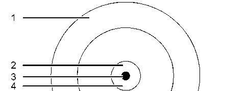
Listed below are the five basic levels of position accuracy that are available.
"Autonomous" - 10 m (30 ft) to 15 m (50 ft)
"SBAS" - 1 m (3.3 ft) to 2 m (6.6 ft)
"DGPS" - 0.3 m (1.0 ft) to 1.0 m (3.0 ft)
"RTK Float" - 0.2 m (0.7 ft) to 1.0 m (3.0 ft)
"RTK Fixed" - .02 m (.07 ft) to .03 m (.10 ft)
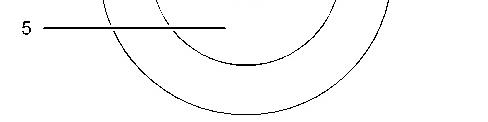
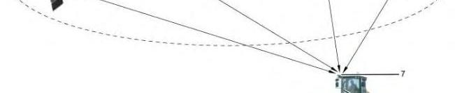
Illustration 1 shows the levels of accuracy for GPS.
Illustration 1
GPS levels of accuracy
(1) "Autonomous"
(2) "DGPS"
(3) "RTK Fixed"
(4) "RTK Float"
(5) "SBAS"
g01374212
Illustration 2 g03037716
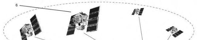
GPS and the Cat® Compaction Value System
(6) GPS satellite constellation
(7) Rover receiver
(8) Rover data radio
Low accuracy corrected GPS (SBAS)
If low accuracy satellite positions are adequate for the required site work, you can use Satellite-Based Augmentation System (SBAS) error corrections. SBAS corrected systems do not require additional site infrastructure.
Satellite-Based Augmentation Systems (SBAS) are free-to-air satellite correction services. SBAS networks consist of ground stations that are set at known positions around the world, and geostationary satellites that maintain a fixed position above the earth. The ground stations receive satellite signals from all satellites in view. The satellite data is then sent to a master control site, which then transmits satellite corrections to the geostationary satellites. These satellites broadcast the information to all SBAS enabled satellite receivers.
The following SBAS networks are currently available:
WAAS - Wide Area Augmentation System (United States)
EGNOS - European Geostationary Navigation Overlay Service (Europe)
MSAS - Multi-Functional Satellite Augmentation System (Japan)
Satellite uses receiver configuration file (".cfg") to convert from WGS84 coordinates to the site coordinate system. High accuracy (RTK) satellite systems use a configuration file generated from the site calibration. Inaccuracies in the entered position of the base station for the site calibration will result in a shift of the site coordinate system away from the local circuit coordinate system. When this configuration file is used by a satellite receiver using RTK, the shift is not exposed. As the relative positions of points on the site are still accurately known, and the accuracy of RTK positioning is
unaffected. However, if the same configuration file is used by a satellite receiver using SBAS corrections, the shift in the site coordinate system away from the local circuit is exposed, and results in additional positioning errors.
To avoid additional errors, do one of the following:
• Make sure the base station antenna position used for the RTK site calibration is accurate to within about 1 m (3.3 ft). This accuracy can be achieved via traditional surveying methods or long autonomous satellite occupations. Speak to your site surveyor for more information.
• Use a configuration file generated by the Cat® Compaction Control software using the local circuit coordinate system, instead of the configuration file produced by the site calibration.
GPS Site Calibration
Note: A GPS site calibration that is poor in quality will result in low quality guidance information from the Cat® Compaction Control.
Satellite site calibration is a mathematical relationship between a grid coordinate system (northing, easting, and elevation) of a project and the satellite coordinate system (latitude, longitude, and ellipsoidal height, also known as WGS84 coordinates).
This relationship is determined by using satellite to measure points with known grid coordinates, and then calculating the calibration parameters.
A surveying or civil engineering company should be used to establish the control points around a site. Make sure that you locate the control points to prevent destroying the points during construction. Five or more control points located at, or near, the corners and center of the project will normally give good results.
Note: If you employ a satellite surveyor to create the satellite site calibration, make sure that you clearly specify the requirements. Caterpillar recommends that you give a copy of this section of the manual to the surveyor.
Some survey software can do both a full site calibration and a single point calibration.
A single point calibration cannot provide any guarantee of accuracy as the parameters that define a site calibration will be default values that may have no resemblance to the real values obtained through a full calibration. A single point calibration should only be employed on small sites with no existing control. Caterpillar recommends that you carry out a full site calibration to guarantee the required accuracy all over the site.
When doing a site calibration, pay attention to the following points:
• A minimum of five 3D local grid coordinates (north, east, elevation) and five observed satellite coordinates (latitude, longitude, height) to provide enough redundancy.
• Independently obtain a set of satellite coordinates from the set of grid coordinates.
• The selected calibration points should be around the perimeter of the site. Do not work outside of the area enclosed by the calibration points, as the calibration is not valid beyond this perimeter.
• When defining the acceptable accuracy limits, the calibration tolerances should not be larger than the accuracy tolerance for the site.
• When measuring points, use a bipod on a staff or a tripod to maintain stability.
• Check the accuracy of the calibration by visiting other control points that were not used in the calibration.
Converting The Site Calibration To A satellite Configuration File
When the site calibration is complete, the site surveyor uses a surveying software package to convert the site calibration data to a calibration file, for example Site.dc.
Once the site calibration file is generated, use Cat® Compaction Control software to convert the calibration to a satellite configuration file which can then be copied to the USB flash drive. For information on how to convert the files, refer to the Cat® Compaction Control help file.
The site calibration files are stored in the display rather than the satellite receiver. For this reason, each time you change site, make sure that you update the site calibration files.
To ensure that the correct files for each design are in use, do one of the following:
• Make sure that there is a valid configuration (".cfg") file for the design in each design folder. When you load the design, the associated configuration file is sent to the receiver.
• Use the "satellite receiver configuration" item in the setup menu. This receiver sends the site calibration to the satellite receiver and updates the parameters that are held in the display.
When a satellite receiver configuration (".cfg") file is sent to a satellite receiver, the system resets the receiver to factory defaults before applying new settings.
Control Levels and Guidance Information
The Cat® Compaction Control can provide the following levels of guidance:
3D Guidance - 3D guidance uses the 3D location of the machine to provide cutting edge guidance relative to an internal 3D digital design. 3D guidance is useful for constructing complex designs, such as highways and curved banks.
In addition, each level of guidance can provide different types of guidance information. The Cat® Compaction Control can provide the following types of cutting edge guidance information:
Lift - Maintains a constant elevation.
One-Point 3D - One-point 3D guidance reports the height of the cutting edge relative to the elevation of a design surface directly below a single point on the drum, and the horizontal offset of one tip of the drum relative to a design feature. The height is calculated by assuming that the cutting edge is at right angles to the direction of travel of the machine.
Copyright 1993 - 2024 Caterpillar Inc. All Rights Reserved. Private Network For SIS Licensees. Thu Jul 11 16:36:11 UTC+0530 2024
Product: VIBRATORY COMPACTOR
Model: CS78B VIBRATORY COMPACTOR M78
Configuration: CS78B, CS79B Vibratory Soil Compactor M7800001-UP (MACHINE) POWERED BY C7.1 Engine
Operation and Maintenance Manual
Cat® Grade Control for Soil Compactors Media Number -KEBU7578-02
Avoidance Zone - Set
SMCS - 7220-529
i04808878
Note: The contents of the "Setup Menu" are configurable at the job site. The number of items that are in the "Setup Menu" may vary depending on the "Operator Configuration" settings of your system and the machine settings. Refer to your supervisor if a specific option is not available.
You can set the distance for avoidance zones with the "Avoidance Zone" dialog. This distance allows you to configure the distance from an avoidance zone when you need to be warned.
Perform the following steps in order to access the "Avoidance Zone" dialog.
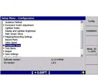
Illustration 1
g02702880
1. From the "Setup Menu – Configuration" dialog, press the arrow keys until "Avoidance Zone" is highlighted.
2. Press the "OK" key. A dialog that is similar to Illustration 2 appears.
3. Do one of the following.
Press the arrow keys in order to set the warning distance.
Press the "Default <value>" soft key in order to set the default warning distance for the selected machine type.
4. Press the "OK" key in order to confirm the setting.
5. Press the escape key in order to exit the "Setup Menu – Configuration" dialog. The changes take effect immediately.