DOWNLOAD LINK
For some reason if link does not work download this pdf and then click
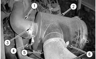
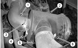
2. Loosen clamp (3) and disconnect hose (1) from air cleaner housing (2) .
3. Loosen clamp (6) and disconnect hose (5) from air cleaner housing (2) .
4. Disconnect tube (4) from the air cleaner housing.
2
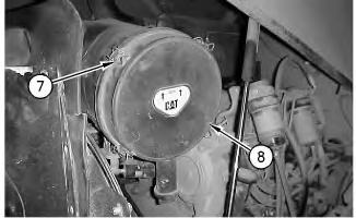
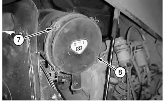
5. Loosen clamps (7) and remove cover (8) from the air cleaner housing. Remove the seal from cover (5). Check the seal for wear or damage. If any wear or damage is present, replace the seal.
3
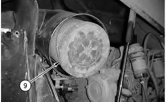
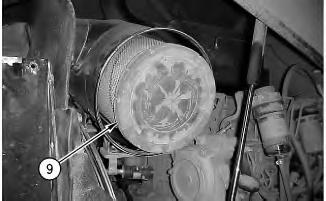
6. Remove primary filter (9) from the air cleaner housing.
Illustration
g00895855
Illustration
g00895852
Illustration 4
g00895856
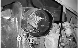
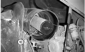
7. Remove secondary filter (10) from the air cleaner housing.
Illustration 5
g00895850
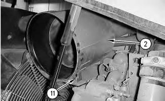
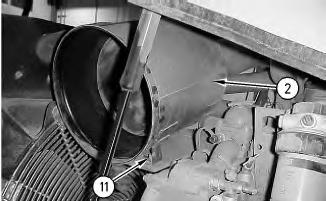
8. Remove bolts (11) and remove air cleaner housing (2) from the bracket.
Installation Procedure
Illustration 6 g00895850
1. Position air cleaner housing (2) on the bracket and install bolts (11) .
Illustration 7
g00895856
2. Install secondary filter (10) in the air cleaner housing.
Illustration 8
g00895852
3. Install primary filter (9) in the air cleaner housing.
9
4. Install the seal in cover (8). Install cover (8) on the air cleaner housing and tighten clamps (7) .
Illustration 10
g00895854
5. Connect tube (4) to the air cleaner housing.
6. Connect hose (5) to air cleaner housing (2) and tighten clamp (6) .
7. Connect hose (1) to air cleaner housing (2) and tighten clamp (3) .
8. Close the engine hood. Copyright 1993 - 2025 Caterpillar Inc.
Illustration
g00895855
Product: VIBRATORY COMPACTOR
Model: CS-583E VIBRATORY COMPACTOR DAJ
Configuration: CS-583E Vibratory Compactor DAJ00001-UP (MACHINE) POWERED BY 3056E Engine
Disassembly and Assembly
CP-563E, CS-563E, CP-573E, CS-573E and CS-583E Vibratory Compactors Engine Supplement
Media Number -KENR3603-02
Air Inlet Heater - Remove and Install
SMCS - 1090-010
Removal Procedure
Hot engine components can cause injury from burns. Before performing maintenance on the engine, allow the engine and the components to cool.
NOTICE
Care must be taken to ensure that fluids are contained during performance of inspection, maintenance, testing, adjusting and repair of the product. Be prepared to collect the fluid with suitable containers before opening any compartment or disassembling any component containing fluids.
Refer to Special Publication, NENG2500, "Caterpillar Tools and Shop Products Guide" for tools and supplies suitable to collect and contain fluids on Caterpillar products.
Dispose of all fluids according to local regulations and mandates.
1. Open the engine hood.
i02161370
Illustration 1
g00896023
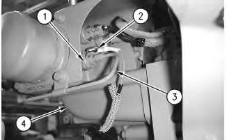
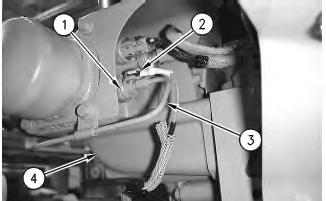
2. Disconnect harness assembly (2) from heater (1) .
3. Disconnect fuel line (3) from heater (1) .
4. Remove heater (1) from air inlet manifold (4) .
Installation Procedure
Illustration 2
1. Install heater (1) in air inlet manifold (4) .
g00896023
2. Connect fuel line (3) to heater (1) .
3. Connect harness assembly (2) to heater (1) .
4. Close the engine hood.
Product: VIBRATORY COMPACTOR
Model: CS-583E VIBRATORY COMPACTOR DAJ
Configuration: CS-583E Vibratory Compactor DAJ00001-UP (MACHINE) POWERED BY 3056E Engine
Disassembly and Assembly
CP-563E, CS-563E, CP-573E, CS-573E and CS-583E Vibratory Compactors Engine Supplement
Media Number -KENR3603-02
Alternator - Remove and Install
SMCS - 1405-010
Removal Procedure
Hot engine components can cause injury from burns. Before performing maintenance on the engine, allow the engine and the components to cool.
1. Open the engine hood.
2. Turn the disconnect switch to the OFF position.
-15/12/2005
i02161359
1
2
Note: Label all electrical wires for installation purposes.
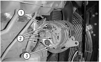
3. Disconnect wires (2) from alternator (3) .
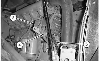
4. Loosen bolts (1) and (4). Rotate alternator (3) toward the engine.
5. Remove belt (5) from the alternator pulley.
6. Remove bolts (1) and (4) and remove alternator (3) from the bracket.
Installation Procedure
Illustration
g00896124
3
4
Note: If the alternator pulley was removed, apply Tooling (A) on the threads. Tighten the alternator pulley to a torque of 90 ± 5 N·m (66 ± 4 lb ft).
1. Position alternator (3) on the bracket and install bolts (1) and (4). Do not tighten the bolts at this time.
2. Install belt (5) on the alternator pulley.
Note: Adjust the belt tension. Refer to the Operation and Maintenance Manual, "BeltsInspect/Adjust/Replace" in order to adjust the belt tension for the alternator.
3. Tighten bolts (1) and (4) .
4. Connect wires (2) .
5. Turn the disconnect switch to the ON position.
6. Close the engine hood.
SIS Licensees. Fri Jan 17 12:52:59 UTC+0530 2025
Illustration
g00896119
Product: VIBRATORY COMPACTOR
Model: CS-583E VIBRATORY COMPACTOR DAJ
Configuration: CS-583E Vibratory Compactor DAJ00001-UP (MACHINE) POWERED BY 3056E Engine
Disassembly and Assembly
CP-563E, CS-563E, CP-573E, CS-573E and CS-583E Vibratory Compactors Engine Supplement
Media Number -KENR3603-02 Publication Date -01/12/2005 Date Updated -15/12/2005
Battery and Battery Cable - Separate and Connect
SMCS - 1401-029-KA
Separation Procedure
i01848129
1. Turn the engine start switch to the OFF position. Turn all switches to the OFF position.
2. Turn the battery disconnect switch to the OFF position. Remove the battery disconnect switch key.
Illustration 1 g00943774
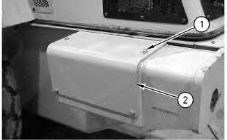
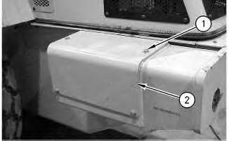
3. Remove bolts (1) and cover (2) from both sides of the machine.
2
Note: Do not allow the disconnected battery cables to contact the disconnect switch. Do not allow the disconnected battery cables to contact the other cables. Do not allow the disconnected battery cables to contact the opposite terminal of either battery.
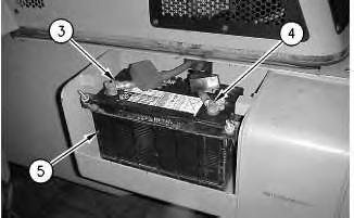
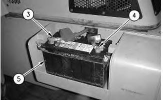
4. Disconnect battery cable (3) from battery (5) .
5. Disconnect battery cable (4) from battery (5) .
Illustration 3
g00943777
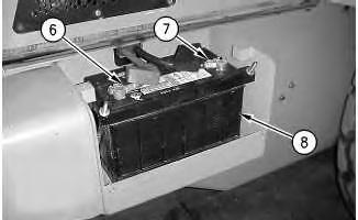
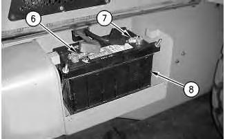
6. Disconnect battery cable (6) from battery (8) .
7. Disconnect battery cable (7) from battery (8) .
Connection Procedure
Illustration
g00943776
4
Note: Do not allow the disconnected battery cables to contact the disconnect switch. Do not allow the disconnected battery cables to contact the other cables. Do not allow the disconnected battery cables to contact the opposite terminal of either battery.
1. Connect battery cable (7) to battery (8) .
2. Connect battery cable (6) to battery (8) .
Illustration 5
3. Connect battery cable (4) to battery (5) .
4. Connect battery cable (3) to battery (5) .
Illustration
g00943777
g00943776
5. Install cover (2) and bolts (1) on both sides of the machine.
Copyright 1993 - 2025 Caterpillar Inc. All Rights Reserved. Private Network For SIS Licensees. Fri Jan 17 12:52:06 UTC+0530 2025
Product: VIBRATORY COMPACTOR
Model: CS-583E VIBRATORY COMPACTOR DAJ
Configuration: CS-583E Vibratory Compactor DAJ00001-UP (MACHINE) POWERED BY 3056E Engine
Disassembly and Assembly
CP-563E, CS-563E, CP-573E, CS-573E and CS-583E Vibratory Compactors Engine Supplement Media Number -KENR3603-02
Updated -15/12/2005 i01939090
Electric Starting Motor - Remove and Install
SMCS - 1453-010
Removal Procedure
Hot engine components can cause injury from burns. Before performing maintenance on the engine, allow the engine and the components to cool.
1. Open the engine hood.
2. Turn the battery disconnect switch to the OFF position. Refer to Operation and Maintenance Manual, "Battery Disconnect Switch".
Illustration 1
g00944052
Note: Put identification marks on all wires and cable assemblies for installation purposes.
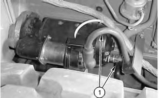
3. Disconnect cable assemblies (1) from the electric starting motor.
Illustration 2
g00944054
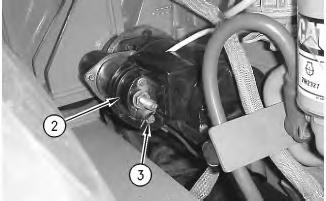
4. Remove nut (3). Remove cover (2) from the electric starting motor.
Illustration 3
g00944055
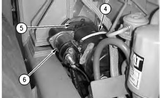
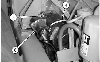
5. Disconnect wire (4) from electric starting motor (6) .
6. Attach a lifting sling and a suitable lifting device to electric starting motor (6). Remove three bolts (5). Remove electric starting motor (6) from the engine. The weight of the electric starting motor is approximately 26 kg (57 lb).
Installation Procedure
4
1. Use a lifting sling and a suitable lifting device to install electric starting motor (6) on the engine. The weight of the electric starting motor is approximately 26 kg (57 lb). Install three bolts (5) .
2. Install wire (4) on electric starting motor (6) .
5
3. Install cover (2) on the electric starting motor. Install nut (3) .
Illustration
g00944055
Illustration
g00944054
4. Install cable assemblies (1) on the electric starting motor.
5. Turn the battery disconnect switch to the ON position. Refer to Operation and Maintenance Manual, "Battery Disconnect Switch".
6. Close the engine hood.
Product: VIBRATORY COMPACTOR
Model: CS-583E VIBRATORY COMPACTOR DAJ
Configuration: CS-583E Vibratory Compactor DAJ00001-UP (MACHINE) POWERED BY 3056E Engine
Disassembly and Assembly
CP-563E, CS-563E, CP-573E, CS-573E and CS-583E Vibratory Compactors Engine Supplement
i02011815
Engine - Install SMCS - 1000-012
Installation Procedure Table 1
Required Tools
Illustration 1
2
Note: Apply Tooling (D) to the mount assemblies during the installation of the engine.
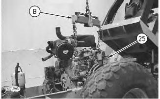
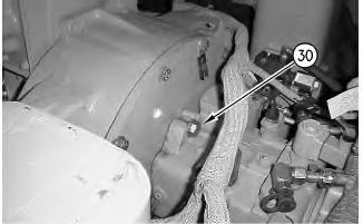
1. Use Tooling (B) and a suitable lifting device to install engine (25) in the machine. Align the splines on the propel pump with the splines on the flange of the pump drive. Use Tooling (B) and the suitable lifting device in order to move the engine toward the front of the machine and install bolts (30) .
3
Illustration
g00944761
Illustration
g00944759
4
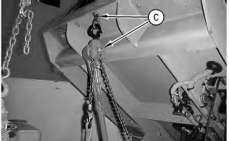
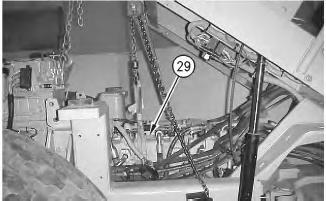
2. Remove the lifting sling from propel pump (29). Remove Tooling (C) from the operator platform.
5
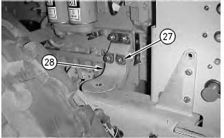
3. Install support (28) and nuts (27) on both sides of the engine.
6
Illustration
g00944760
Illustration
g00944750
Illustration
g00944749
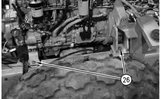
4. Lower the engine and install bolts (26) on both sides of the engine. Remove Tooling (B) and the suitable lifting device from engine (25) .
7
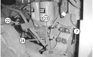
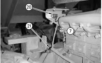
5. Install the cable strap that fastens harness assembly (7) to bracket (22) .
6. Install bolts (23) that fasten plate (24) to the engine.
7. Install the cable straps that fasten harness assembly (7) to the engine.
8
8. Install the bolt that fastens clamp (21) and harness assembly (7) to the support.
9. Install the two wires on resistor (20). Install the cable straps that fasten harness assembly (7) to the bracket.
Illustration
g00944747
Illustration
g00944746
9
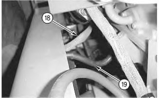
10. Install ground strap (18) and cable assembly (19) on the ground stud that is welded on the frame and install the nut.
10
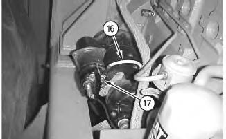
Install wire (16) on the electric starting motor. Install nut (17) .
11
Illustration
g00944745
Illustration
g00944743
11.
Illustration
g00944742
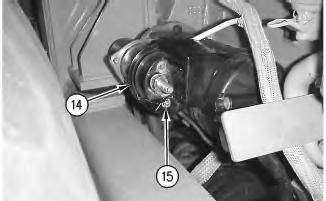
12. Install cover (14) on the electric starting motor. Install nut (15) .
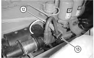
13. Install cable assembly (12) on the electric starting motor.
14. Install clamp (13) that fastens cable assembly (12) to the bracket.
13
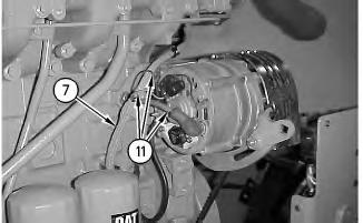
15. Connect wires (11) to the alternator.
16. Install the cable straps that fasten harness assembly (7) to the engine.
Illustration 12
g00944741
Illustration
g00944740
This is the sample of the manual click on the download link for complete manual