


CS-563D VIBRATORY COMPACTOR


Product: VIBRATORY COMPACTOR
Model: CS-563D VIBRATORY COMPACTOR 9MW
Configuration: CS-563D CP-563D Vibratory Compactors 9MW00001-UP (MACHINE) POWERED BY 3116 Engine
Operation and Maintenance Manual
CP-563D, CS-563D, CS-573D and CS-583D Paving Compactors
Foreword
Literature Information
s00037320
This manual should be stored in the operator's compartment in the literature holder or seat back literature storage area.
This manual contains safety information, operation instructions, transportation information, lubrication information and maintenance information.
Some photographs or illustrations in this publication show details or attachments that can be different from your machine. Guards and covers might have been removed for illustrative purposes.
Continuing improvement and advancement of product design might have caused changes to your machine which are not included in this publication. Read, study and keep this manual with the machine.
Whenever a question arises regarding your machine, or this publication, please consult your Cat dealer for the latest available information.
Safety
The safety section lists basic safety precautions. In addition, this section identifies the text and locations of warning signs and labels used on the machine.
Read and understand the basic precautions listed in the safety section before operating or performing lubrication, maintenance and repair on this machine.
Operation
The operation section is a reference for the new operator and a refresher for the experienced operator. This section includes a discussion of gauges, switches, machine controls, attachment controls, transportation and towing information.
Photographs and illustrations guide the operator through correct procedures of checking, starting, operating and stopping the machine.
Operating techniques outlined in this publication are basic. Skill and techniques develop as the operator gains knowledge of the machine and its capabilities.
Maintenance
The maintenance section is a guide to equipment care. The Maintenance Interval Schedule (MIS) lists the items to be maintained at a specific service interval. Items without specific intervals are listed under the "When Required" service interval. The Maintenance Interval Schedule lists the page number for the step-by-step instructions required to accomplish the scheduled maintenance. Use the Maintenance Interval Schedule as an index or "one safe source" for all maintenance procedures.
Maintenance Intervals
Use the service hour meter to determine servicing intervals. Calendar intervals shown (daily, weekly, monthly, etc.) can be used instead of service hour meter intervals if they provide more convenient servicing schedules and approximate the indicated service hour meter reading. Recommended service should always be performed at the interval that occurs first.
Under extremely severe, dusty or wet operating conditions, more frequent lubrication than is specified in the maintenance intervals chart might be necessary.
Perform service on items at multiples of the original requirement. For example, at every 500 service hours or 3 months, also service those items listed under every 250 service hours or monthly and every 10 service hours or daily.
California Proposition 65 Warning
Diesel engine exhaust and some of its constituents are known to the State of California to cause cancer, birth defects, and other reproductive harm.
Battery posts, terminals and related accessories contain lead and lead compounds. Wash hands after handling.
Certified Engine Maintenance
Proper maintenance and repair is essential to keep the engine and machine systems operating correctly. As the heavy duty off-road diesel engine owner, you are responsible for the performance of the required maintenance listed in the Owner Manual, Operation and Maintenance Manual, and Service Manual.
It is prohibited for any person engaged in the business of repairing, servicing, selling, leasing, or trading engines or machines to remove, alter, or render inoperative any emission related device or element of design installed on or in an engine or machine that is in compliance with the regulations (40 CFR Part 89). Certain elements of the machine and engine such as the exhaust system, fuel system, electrical system, intake air system and cooling system may be emission related and should not be altered unless approved by Caterpillar.
Machine Capacity
Additional attachments or modifications may exceed machine design capacity which can adversely affect performance characteristics. Included would be stability and system certifications such as brakes, steering, and rollover protective structures (ROPS). Contact your Cat dealer for further information.
Cat Product Identification Number
Effective First Quarter 2001 the Cat Product Identification Number (PIN) has changed from 8 to 17 characters. In an effort to provide uniform equipment identification, Caterpillar and other construction equipment manufacturers are moving to comply with the latest version of the product identification numbering standard. Non-road machine PINs are defined by ISO 10261. The new PIN format will apply to all Cat machines and generator sets. The PIN plates and frame marking will display the 17 character PIN. The new format will look like the following:
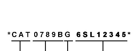
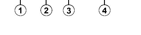
Illustration 1 g00751314
Where:
1. Caterpillar's World Manufacturing Code (characters 1-3)
2. Machine Descriptor (characters 4-8)
3. Check Character (character 9)
4. Machine Indicator Section (MIS) or Product Sequence Number (characters 10-17). These were previously referred to as the Serial Number.
Machines and generator sets produced before First Quarter 2001 will maintain their 8 character PIN format.
Components such as engines, transmissions, axles, etc. and work tools will continue to use an 8 character Serial Number (S/N). Copyright 1993 - 2024 Caterpillar Inc. All Rights Reserved. Private Network For SIS Licensees.
Product: VIBRATORY COMPACTOR
Model: CS-563D VIBRATORY COMPACTOR 9MW
Configuration: CS-563D CP-563D Vibratory Compactors 9MW00001-UP (MACHINE) POWERED BY 3116 Engine
Operation and Maintenance Manual
CP-563D, CS-563D, CS-573D and CS-583D Paving Compactors
Air Conditioner - Test - If Equipped
SMCS - 7320-081; 7320
i01084958
Before warm weather begins, check the refrigerant. Also check the refrigerant if the air conditioning system does not function properly.
Open the engine compartment.
When the outside temperature is higher than 21°C (70°F), operate the air conditioning system for five to ten minutes.
When the system needs refrigerant, see your Caterpillar dealer for proper installation.
Operate the air conditioner monthly in order to lubricate the compressor seals. Set the controls on the maximum setting. Operate the system for 15 minutes.
Close the engine compartment.
Copyright 1993 - 2024 Caterpillar Inc. All Rights Reserved. Private Network For SIS Licensees. Thu Dec 19 02:56:28 UTC+0530 2024
Product: VIBRATORY COMPACTOR
Model: CS-563D VIBRATORY COMPACTOR 9MW
Configuration: CS-563D CP-563D Vibratory Compactors 9MW00001-UP (MACHINE) POWERED BY 3116 Engine
Operation and Maintenance Manual
CP-563D, CS-563D, CS-573D and CS-583D Paving Compactors
Axle Oil (Rear) - Change
SMCS - 3260-044; 3278-044; 3278
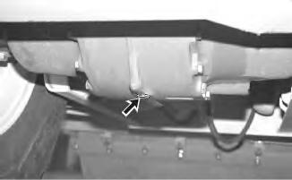
Illustration 1
i01234081
g00659994
1. Remove the differential drain plug. The plug is located at the bottom of the differential case. Note: Drain the oil into a suitable container. Dispose of the used oil in an appropriate manner.
2. Remove the differential level/fill plug. The differential level/fill plug is located on the back side of the axle.
3. Clean the drain plug and install the drain plug. Add the proper oil to the differential. Maintain the level of the oil to the bottom of the hole for the differential level/fill plug. Refer to the Operation and Maintenance Manual, "Lubricant Viscosities and Refill Capacities" section for more information.
4. Clean the filler plug. Install the filler plug.
Copyright 1993 - 2024 Caterpillar Inc.
Product: VIBRATORY COMPACTOR
Model: CS-563D VIBRATORY COMPACTOR 9MW
Configuration: CS-563D CP-563D Vibratory Compactors 9MW00001-UP (MACHINE) POWERED BY 3116 Engine
Operation and Maintenance Manual
CP-563D, CS-563D, CS-573D and CS-583D Paving Compactors
Media Number -KEBU7503-08 Publication Date -01/08/2005
Axle Oil Level (Rear) - Check
SMCS - 3260-535-FLV; 3278-535; 3278
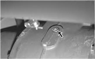
Illustration 1 g00654323
Note: The differential level/fill plug is located on the back side of the rear axle.
Updated -05/08/2005
1. Remove the level/fill plug. Maintain the oil level to the bottom of the level/fill plug opening. If necessary, add oil.
2. Clean the level/fill plug. Install the plug.
Copyright 1993 - 2024 Caterpillar Inc. All Rights Reserved. Private Network For SIS Licensees. Thu Dec 19 02:56:51 UTC+0530 2024
Product: VIBRATORY COMPACTOR
Model: CS-563D VIBRATORY COMPACTOR 9MW
Configuration: CS-563D CP-563D Vibratory Compactors 9MW00001-UP (MACHINE) POWERED BY 3116 Engine
Operation and Maintenance
Manual
CP-563D, CS-563D, CS-573D and CS-583D Paving Compactors
Media Number -KEBU7503-08 Publication Date -01/08/2005 Date Updated -05/08/2005
Axle Oil Sample - Obtain
SMCS - 3260-008; 3278-008; 7542
Illustration 1 g00659994
The drain plug is located on the bottom of the differential.
i01316767
Refer to the Caterpillar Machine Fluids Recommendations, SEBU6250, "Cooling System specifications" and refer to the Operation and Maintenance Manual, "Sampling Interval and Location of Sampling Valve" for more information.
Copyright 1993 - 2024 Caterpillar Inc. All Rights Reserved. Private Network For SIS Licensees. Thu Dec 19 02:57:08 UTC+0530 2024
Product: VIBRATORY COMPACTOR
Model: CS-563D VIBRATORY COMPACTOR 9MW
Configuration: CS-563D CP-563D Vibratory Compactors 9MW00001-UP (MACHINE) POWERED BY 3116 Engine
Operation and Maintenance Manual
CP-563D, CS-563D, CS-573D and CS-583D Paving Compactors
Media Number -KEBU7503-08 Publication Date -01/08/2005 Date Updated -05/08/2005
Backup Alarm - Test
SMCS - 7406-081
The backup alarm is located at the rear of the machine.
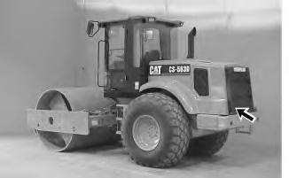
Illustration 1
i01206670
g00644956
Turn the engine start switch to the ON position in order to perform the test.
Apply the parking brake. Move the propel control lever to the REVERSE position.
The backup alarm should start to sound immediately. The backup alarm will continue to sound until the transmission control lever is moved to the STOP position or to the FORWARD position.
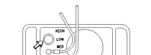

Illustration 2 g00100238
In order to adjust the volume level, turn the three-position selector switch. The switch is located on the back of the backup alarm. When the machine is shipped from the factory, the three-position selector switch is set to the HIGH setting. The three-position selector switch should remain at the HIGH setting unless the job site requires a lower volume level.
Copyright 1993 - 2024 Caterpillar Inc. All Rights Reserved. Private Network For SIS Licensees. Thu Dec 19 02:57:21 UTC+0530 2024
Product: VIBRATORY COMPACTOR
Model: CS-563D VIBRATORY COMPACTOR 9MW
Configuration: CS-563D CP-563D Vibratory Compactors 9MW00001-UP (MACHINE) POWERED BY 3116 Engine
Operation and Maintenance Manual
CP-563D, CS-563D, CS-573D and CS-583D Paving Compactors
Media Number -KEBU7503-08 Publication Date -01/08/2005 Date Updated -05/08/2005
i01152360
Battery - Clean/Check
SMCS - 1401-070; 1401-535; 1402-070; 1402-535
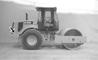
1 g00611756
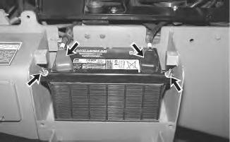
Note: The batteries that are supplied with the machines are maintenance free batteries. You do not need to check the level of the electrolyte in the maintenance free batteries.
Tighten the battery retainers on both of the batteries. Tighten the battery retainers at every 1000 hours. Check the following items at every 1000 hours. If necessary, check the following items more often.
• Clean the top of the batteries with a clean cloth.
• Clean the battery terminals. As needed, coat the battery terminals with petroleum jelly.
1993 - 2024 Caterpillar Inc.
Product: VIBRATORY COMPACTOR
Model: CS-563D VIBRATORY COMPACTOR 9MW
Configuration: CS-563D CP-563D Vibratory Compactors 9MW00001-UP (MACHINE) POWERED BY 3116 Engine
Operation and Maintenance Manual
CP-563D, CS-563D, CS-573D and CS-583D Paving Compactors
Media Number -KEBU7503-08
Publication Date -01/08/2005
Battery - Recycle
SMCS - 1401-561
Always recycle a battery. Never discard a battery.
Always return used batteries to one of the following locations:
• A battery supplier
• An authorized battery collection facility
• Recycling facility
Date Updated -05/08/2005
i06543763
Copyright 1993 - 2024 Caterpillar Inc. All Rights Reserved. Private Network For SIS Licensees. Thu Dec 19 02:57:45 UTC+0530 2024
Product: VIBRATORY COMPACTOR
Model: CS-563D VIBRATORY COMPACTOR 9MW
Configuration: CS-563D CP-563D Vibratory Compactors 9MW00001-UP (MACHINE) POWERED BY 3116 Engine
Operation and Maintenance Manual
CP-563D, CS-563D, CS-573D and CS-583D Paving Compactors
Belts - Inspect/Adjust/Replace
SMCS - 1357-025; 1357-040; 1357-510
i01451038
Your engine can be equipped with a water pump belt, with a fan drive belt and with accessory drive belts. Your engine can also be equipped with an alternator belt. For maximum engine performance and maximum utilization of your engine, inspect the belts for wear and for cracking. Check the belt tension. Adjust the belt tension in order to minimize belt slippage. Belt slippage will decrease the belt life. Belt slippage will also cause poor performance of the alternator and of any driven equipment.
If new belts are installed, recheck the belt adjustment after 30 minutes of operation. If two belts or more are required for an application, replace the belts in belt sets. If only one belt of a matched set is replaced, the new belt will carry more load. This is due to the fact that the older belts are stretched. The additional load on the new belt could cause the new belt to break.
Alternator Belt
1. Open the engine compartment.
2. To check the belt tension, apply 110 N (25 lb) of force midway between the pulleys. Correctly adjusted belts will deflect 13 to 19 mm (1/2 to 3/4 inch).
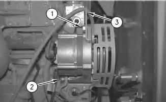
3. In order to adjust the alternator belt, loosen bracket bolt (1) and mounting bolt (2) on the alternator bracket.
4. To achieve the correct adjustment, move the alternator inward or move the alternator outward, as required.
5. If necessary, use a pry bar in the square hole (3) in the alternator bracket.
6. Tighten mounting bolt (2) and bracket bolt (1) .
Note: The alternator shaft nut must be tightened to a torque of 50 ± 5 N·m (37 ± 4 lb ft).
7. If new belts are installed, check the belt and adjustment again after 30 minutes of engine operation at the rated speed.
8. Check the position of the fan shroud. Adjust the position of the fan shroud so that the fan will not rub against the shroud. Maintain a 9.4 mm (0.38 inch) clearance between the fan and the shroud.
Water Pump Belt
1. To check the belt tension, apply 110 N (25 lb) of force midway between the pulleys. Correctly adjusted belts will deflect 13 to 19 mm (1/2 to 3/4 inch).
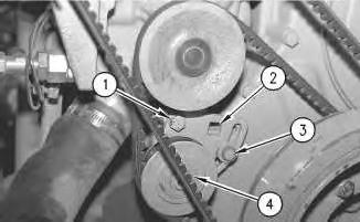
2. To adjust the water pump drive belt, loosen mounting bolt (1) and bracket bolt (3) .
3. Move idler pulley (4) in order to achieve the correct adjustment.
4. If necessary, use a pry bar in square hole (2) in the mounting bracket.
5. Tighten mounting bolt (1) and bracket bolt (3) .
6. If a new belt is installed, run the engine at rated speed for thirty minutes. Check the bolt torque. Readjust the belt, if necessary.
1993 - 2024 Caterpillar Inc.
Product: VIBRATORY COMPACTOR
Model: CS-563D VIBRATORY COMPACTOR 9MW
Configuration: CS-563D CP-563D Vibratory Compactors 9MW00001-UP (MACHINE) POWERED BY 3116 Engine
Operation and Maintenance Manual
CP-563D, CS-563D, CS-573D and CS-583D Paving Compactors
Braking System - Test
SMCS - 4250-081; 4267-081
i01633165
Check the area around the machine. Make sure that the machine is clear of personnel and clear of obstacles.
Test the brakes on a dry, level surface.
Disconnect the line to the gearbox on the CS-433E and the CP-433E. The CS-423E has axle brakes. Plug the port.
Fasten the seat belt before you test the brakes.
The following tests are used to determine if the parking brake is functional. These tests are not intended to measure the maximum brake holding effort. The brake holding effort that is required to sustain a machine at a specific engine rpm will vary depending on the machine. The variations are the differences in the engine setting, and in the power train efficiency, etc.
1. Start the engine and raise the attachment slightly.
2. Apply the parking brake.
3. While the parking brake is applied, move the propel control lever to the FORWARD position.
4. Increase the engine speed to HIGH idle. The machine should not move. The machine will move in LOW range.
Note: If the machine begins to move, reduce the engine speed immediately and move the propel control lever to the NEUTRAL position.
5. Reduce the engine speed to low idle.
6. Move the propel control lever to the NEUTRAL position.
7. Move the propel control lever to the REVERSE position.
8. Gradually increase the engine speed to high idle. The machine should not move.
Note: If the machine begins to move, reduce the engine speed immediately and move the propel control lever to the NEUTRAL position.
9. Reduce the engine speed to low idle.
10. Move the propel control lever to the NEUTRAL position.
11. Lower the attachment to the ground and stop the engine.
NOTICE
If the machine moved while testing the brakes, contact your Caterpillar dealer.
Have the dealer inspect and, if necessary, repair the parking brakes before returning the machine to operation.
1993 - 2024 Caterpillar Inc.
Network For SIS Licensees. Thu Dec 19 02:58:12 UTC+0530 2024
Product: VIBRATORY COMPACTOR
Model: CS-563D VIBRATORY COMPACTOR 9MW
Configuration: CS-563D CP-563D Vibratory Compactors 9MW00001-UP (MACHINE) POWERED BY 3116 Engine
Operation and Maintenance Manual
CP-563D, CS-563D, CS-573D and CS-583D Paving Compactors
Media Number -KEBU7503-08 Publication Date -01/08/2005 Date Updated -05/08/2005
Cab Air Filter - Clean/Replace
SMCS - 7342-070; 7342-510
The cab air filter is located to the left of the seat.
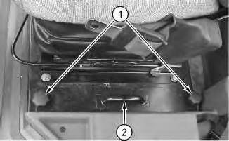
Illustration 1
1. Remove two hand knobs (1) .
g00645572
2. To remove the air filters, pull upward on handle (2) .
i01773798
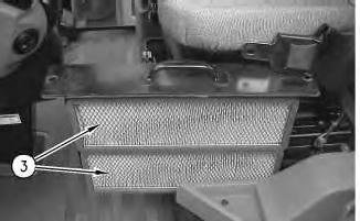
Illustration 2 g00645580
3. Clean air filters (3) with a maximum of 200 kPa (30 psi).
4. After you clean the air filters, inspect the air filters. If the air filters are damaged or badly contaminated, use new air filters.
5. Install the filters in the reverse order of the above steps.
Copyright 1993 - 2024 Caterpillar Inc. All Rights Reserved. Private Network For SIS Licensees. Thu Dec 19 02:58:22 UTC+0530 2024
Product: VIBRATORY COMPACTOR
Model: CS-563D VIBRATORY COMPACTOR 9MW
Configuration: CS-563D CP-563D Vibratory Compactors 9MW00001-UP (MACHINE) POWERED BY 3116 Engine
Operation and Maintenance Manual
CP-563D, CS-563D, CS-573D and CS-583D Paving Compactors
Cab Tilting - If Equipped
SMCS - 7301-509; 7301-084; 7301-506
Raising the Cab
In order to permit easy access to the mechanical components and the hydraulic components, the cab can be tilted forward.
The hydraulic pump is operated manually. The hydraulic pump is used in order to raise the cab. The hydraulic pump is used in order to lower the cab.
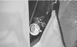
Illustration 1
g00661322
1. Turn off the battery disconnect switch. Remove the key.
2
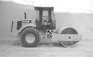
2. There are two side panels. One panel is on the right side of the cab and one panel is on the left side of the cab. Remove the side panels in order to gain access to the electrical connectors.
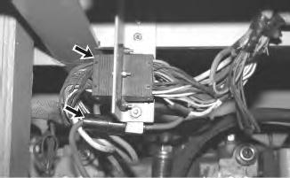
Illustration 3
g00661348
3. Carefully disconnect all of the electrical connectors.
4
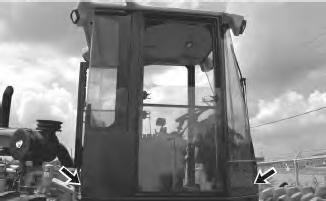
4. Remove the nuts and the bolts that are located at each corner of the cab. In order to remove the rear bolts, remove the plastic molding from the inside corners of the cab. The bolts are under the molding.
5
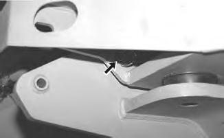
5. Install the pins into the holes for the cab mount pivot. The holes are located under the cab at the front of the cab. The hole on the cab and the hole on the frame are aligned when the cab is in the lowered position. There is one hole on each side of the cab.
6. Follow steps 9 to 14 if your machine is equipped with a hydraulic pump. If your machine does not have a hydraulic pump, then strap a come-along to the front bumper.
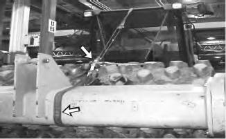
Illustration 6
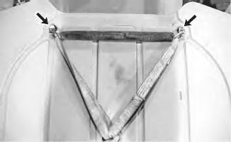
Illustration 7
7. Connect the hook to a strap that is attached to the top of the cab.
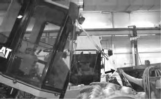
Illustration 8