


Product: VIBRATORY COMPACTOR
Model: CS-433E VIBRATORY COMPACTOR BTT
Configuration: CS/CP-433E Vibratory Compactor BTT00001-UP (MACHINE) POWERED BY 3054C Engine
Disassembly and Assembly
CP-433E, CS-423E and CS-433E
Vibratory Compactors Machine Systems
Media Number -KENR3584-05 Publication Date -01/09/2008 Date Updated -29/09/2008
i02069582
Articulating and Oscillating Hitch - Remove
SMCS - 7057-011; 7113-011
Removal Procedure
Table 1
Required Tools
A 180-3033 Stand 2 B 138-7574 Link Bracket 2
Start By:
A. Remove the drum. Refer to Disassembly and Assembly, "Drum - Remove".
1
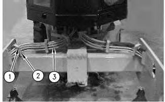
1. Remove bolts (2) and hose guards (1). Move hose assemblies (3) out of the way.
2
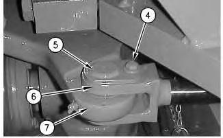
2. Remove bolt (4), pin assembly (5), and steering cylinder (6) from oscillating hitch (7) on both sides of the machine.
3
4
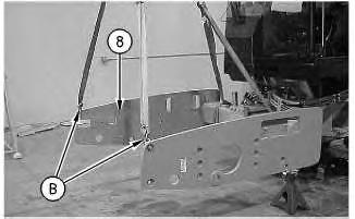
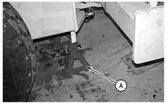
3. Attach a suitable lifting device and Tooling (B) to yoke (8), as shown. Raise yoke (8) and remove Tooling (A) from the yoke. Install Tooling (A) under each side of the machine frame and lower the machine frame onto Tooling (A) .
5
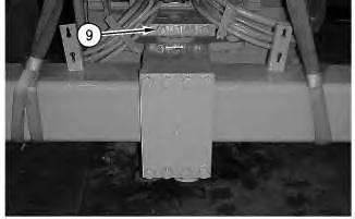
4. Remove bolts (9) and the caps from the yoke and the oscillating hitch. Remove the yoke and the oscillating hitch as a unit from the machine. Position the yoke and the oscillating hitch on wood blocks on the floor. The weight of the yoke and the oscillating hitch is approximately 825 kg (1820 lb).
Copyright 1993 - 2024 Caterpillar Inc. All Rights Reserved. Private Network For SIS Licensees.
Sun Nov 3 11:40:21 UTC+0530 2024

Product: VIBRATORY COMPACTOR
Model: CS-433E VIBRATORY COMPACTOR BTT
Configuration: CS/CP-433E Vibratory Compactor BTT00001-UP (MACHINE) POWERED BY 3054C Engine
Disassembly and Assembly
CP-433E, CS-423E and CS-433E
Vibratory Compactors Machine Systems
Control Valve (Shift) - Remove
SMCS - 5051-011
Removal Procedure
Start By:
A. Tilt the operator platform. Refer to Disassembly and Assembly, "Operator Platform - Tilt".
B. Tilt the cab. Refer to Disassembly and Assembly, "Cab - Tilt".
Table 1
Required Tools
Tool Part
6V-9507 Face Seal Plug (9/16 - 18 THD) 2
6V-9828 Cap Assembly (9/16 - 18 THD) 2
6V-9509 Face Seal Plug (13/16 - 16 THD) 2
6V-9830 Cap Assembly (13/16 - 16 THD) 2
Note: SERVICE DATA: TOOLING (ZZ) WILL NOT BE IDENTIFIED IN PHOTOGRAPHS IN THE REMOVAL OR THE INSTALLATION. THIS TOOLING IS SHOWN IN ORDER TO ASSIST THE EXPERIENCED SERVICEMAN.
Personal injury can result from hydraulic oil pressure and hot oil.
Hydraulic oil pressure can remain in the hydraulic system after the engine has been stopped. Serious injury can be caused if this pressure is not released before any service is done on the hydraulic system.
Make sure all of the work tools have been lowered to the ground, and the oil is cool before removing any components or lines. Remove the oil filler cap only when the engine is stopped, and the filler cap is cool enough to touch with your bare hand.
NOTICE
Care must be taken to ensure that fluids are contained during performance of inspection, maintenance, testing, adjusting, and repair of the machine. Be prepared to collect the fluid with suitable containers before opening any compartment or disassembling any component containing fluids.
Refer to Special Publication, NENG2500, "Caterpillar Tools and Shop Products Guide"for tools and supplies to collect and contain fluids in Caterpillar machines.
Dispose of all fluids according to local regulations.
Note: Put identification marks on all lines, on all hoses, on all wires, and on all tubes for installation purposes. Plug all lines, hoses, and tubes. This helps to prevent fluid loss and this helps to keep contaminants from entering the system.
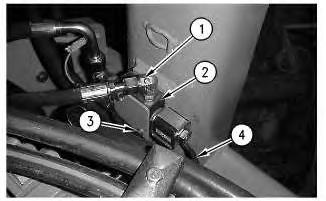
1. Disconnect hose assemblies (1) from the shift valve (2) .
2. Disconnect harness assembly (4) .
3. Remove bolts (3), the plate, and shift valve (2) from the machine.
Copyright 1993 - 2024 Caterpillar Inc. All Rights Reserved. Private Network For SIS Licensees.
Sun Nov 3 11:39:55 UTC+0530 2024
Product: VIBRATORY COMPACTOR
Model: CS-433E VIBRATORY COMPACTOR BTT
Configuration: CS/CP-433E Vibratory Compactor BTT00001-UP (MACHINE) POWERED BY 3054C Engine
Disassembly and Assembly
CP-433E, CS-423E and CS-433E
Vibratory Compactors Machine Systems
Eccentric Weight Housing - Install
SMCS - 6606-012
Installation Procedure
Table 1
Required Tools
i02071576
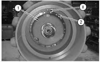
Illustration 2
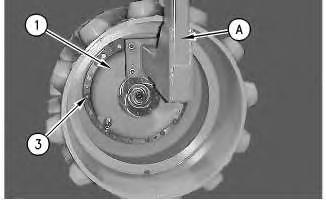
1. Attach Tool (A) on eccentric weight (1). Install guide bolts (3) in the drum. Install the eccentric weight. The weight of the eccentric weight is approximately 330 kg (727 lb).
2. Apply Tooling (B) to the threads of the bolts (2) and install the bolts.
3. Remove Tool (A) from eccentric weight (1). Install remaining bolts (2) .
4. Flush the eccentric weight housing. Refer to Special Instruction, SEHS988-01 for the correct procedure.
5. Fill the eccentric weight housing with oil. The capacity of the eccentric weight housing is approximately 11.83 L (3.12 US gal).
End By: Install the vibratory support. Refer to Disassembly and Assembly, "Vibratory SupportInstall".
Product: VIBRATORY COMPACTOR
Model: CS-433E VIBRATORY COMPACTOR BTT
Configuration: CS/CP-433E Vibratory Compactor BTT00001-UP (MACHINE) POWERED BY 3054C Engine
Disassembly and Assembly
CP-433E, CS-423E and CS-433E
Vibratory Compactors Machine Systems
Media Number -KENR3584-05
Date -01/09/2008
Control Valve (Shift) - Disassemble
SMCS - 5051-015
Disassembly Procedure
Start By:
Updated -29/09/2008
i02070385
a. Remove the control valve (shift). Refer to Disassembly and Assembly, "Control Valve (Shift) - Remove".
Note: Cleanliness is an important factor. Before the disassembly procedure, the exterior of the component should be thoroughly cleaned. This will help to prevent dirt from entering the internal mechanism.
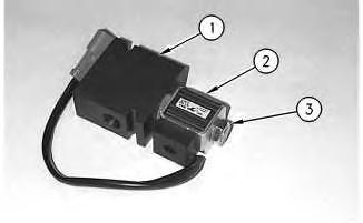
Illustration 1
g00803396
1. Remove nut (3) and coil (2) from valve body (1).
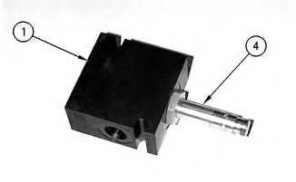
Illustration 2
g00803397
2. Remove valve cartridge (4) from valve body (1).
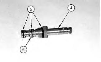
Illustration 3
g00803398
3. Remove O-ring seals (5) and backup ring (6) from valve cartridge (4).
Copyright 1993 - 2024 Caterpillar Inc. All Rights Reserved. Private Network For SIS Licensees. Sun Nov 3 11:39:41 UTC+0530 2024
Product: VIBRATORY COMPACTOR
Model: CS-433E VIBRATORY COMPACTOR BTT
Configuration: CS/CP-433E Vibratory Compactor BTT00001-UP (MACHINE) POWERED BY 3054C Engine
Disassembly and Assembly
CP-433E, CS-423E and CS-433E Vibratory Compactors Machine Systems Media
Eccentric Weight Housing - Assemble
SMCS - 6606-016
Assembly Procedure
Table 1
i02162350
1
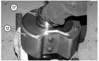
1. Raise the temperature of the inner bearing race (17) to 121 °C (250 °F) and install bearing race (17) onto the shaft of eccentric weight (12). Replace any shims that were removed during disassembly.
2
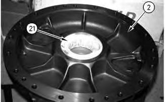
2. Lower the temperature of bearing (21) to -73 °C (-100 °F) and install bearing (21) in cover (2) .
3
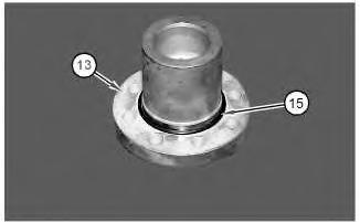
3. Install O-ring seal (15) on shaft (13) .
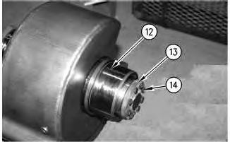
Illustration 4
4. Apply Tooling (G) to the threads of the bolts (14). Install shaft (13) and bolts (14) on eccentric weight (12) .
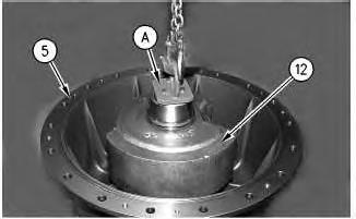
Illustration 5
5. Attach Tooling (A) and install eccentric weight (12) in housing (5). Turn the eccentric weight during installation in order to seat the eccentric weight in the bearing.
6
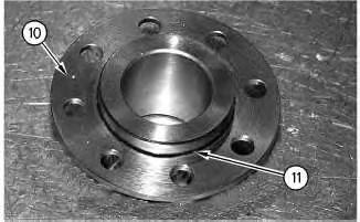
6. Install O-ring seal (11) on flange (10) .

Illustration 7
7. Apply Tooling (G) to the threads of the bolts (9). Install flange (10) to eccentric weight with bolts (9) .
8
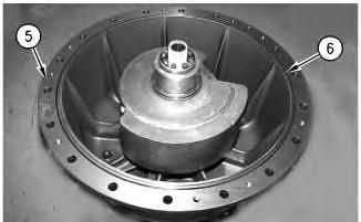
8. Install O-ring seal (6) on housing (5) .
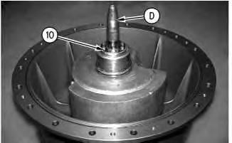
9
10
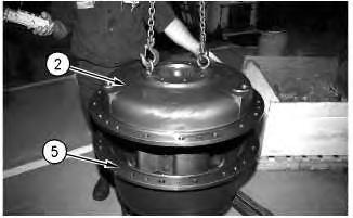
10. Install cover (2) on housing (5). Rotate the cover during installation in order to seat the bearing.
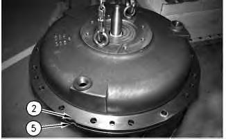
Illustration 11
g00824774
11. Align the notch on cover (2) with the notch on housing (5) .
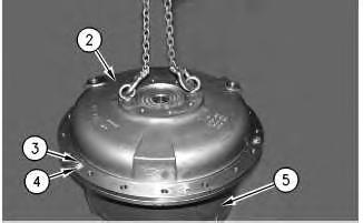
Illustration 12
g00824237
12. Apply Tooling (G) to the threads on the bolts (3). Install bolts (3) and washers (4) .
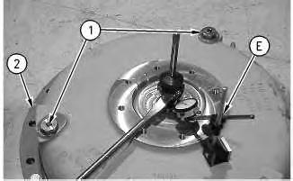
Illustration 13
13. Install drain plugs (1) and cover (2) .
g00824856
14. Use a suitable pry bar and Tooling (E) to check end play. Total end play should not exceed 0.89 ± 0.38 mm (0.035 ± 0.015 inch).
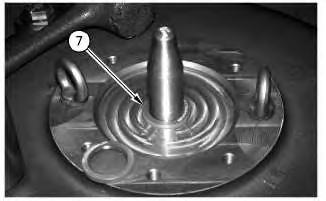
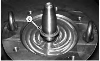

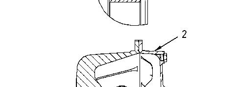
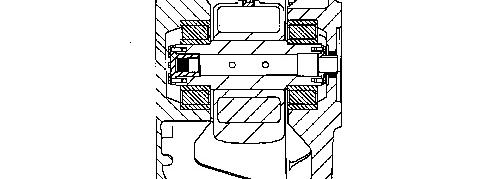

Illustration 16 g00824868
15. Use Tooling (F) to install lip seal (7) and (8) in cover (2) .
End By: Install the eccentric weight housing. Refer to Disassembly and Assembly, "Eccentric Weight Housing - Install".
Copyright 1993 - 2024 Caterpillar Inc. All Rights Reserved.
Network For SIS Licensees.
Sun Nov 3 11:39:25 UTC+0530 2024
Product: VIBRATORY COMPACTOR
Model: CS-433E VIBRATORY COMPACTOR BTT
Configuration: CS/CP-433E Vibratory Compactor BTT00001-UP (MACHINE) POWERED BY 3054C Engine
Disassembly and Assembly
CP-433E, CS-423E and CS-433E
Vibratory Compactors Machine Systems
Media Number -KENR3584-05 Publication Date -01/09/2008 Date Updated -29/09/2008
Control Valve (Shift) - Assemble
SMCS - 5051-016
Assembly Procedure
i02070223
Note: Cleanliness is an important factor. Before assembly, all parts should be thoroughly cleaned in cleaning fluid. Allow the parts to air dry. Wiping cloths or rags should not be used to dry parts. Lint may be deposited on the parts which may cause later trouble. Inspect all parts. If any parts are worn or damaged, use new parts for replacement.
Illustration 1
g00803398
1. Install O-ring seals (5) and backup ring (6) on valve cartridge (4).
Illustration 2
g00803397
2. Install valve cartridge (4) in valve body (1). Tighten the valve cartridge to a torque of 37 N·m (27 lb ft).
Illustration 3
g00803396
3. Install coil (2) and nut (3) on the valve cartridge and valve body (1). Tighten the nut to a torque of 4 N·m (35 lb in).
End By:
a. Install the control valve (shift). Refer to Disassembly and Assembly, "Control Valve (Shift) - Install". Copyright 1993 - 2024 Caterpillar Inc. All Rights Reserved. Private Network For SIS Licensees. Sun Nov 3 11:39:19 UTC+0530 2024
Product: VIBRATORY COMPACTOR
Model: CS-433E VIBRATORY COMPACTOR BTT
Configuration: CS/CP-433E Vibratory Compactor BTT00001-UP (MACHINE) POWERED BY 3054C Engine
Disassembly and Assembly
CP-433E, CS-423E and CS-433E Vibratory Compactors Machine Systems Media
Eccentric Weight Housing - Disassemble
SMCS - 6606-015
Disassembly Procedure
Table 1 Required Tools
i02071648
Start By:
A. Remove the eccentric weight housing. Refer to Disassembly and Assembly, "Eccentric Weight Housing - Remove".
1
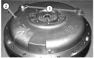
1. Remove drain plugs (1) from cover (2) .
2
2. Remove bolts (3) and washers (4) .
3. Separate cover (2) from housing (5) .
3
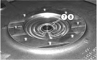
4. Remove O-ring seal (6) from housing (5) .
4