3. Remove bolts (3), the plate, and shift valve (2) from the machine.
Copyright 1993 - 2024 Caterpillar Inc. All Rights Reserved. Private Network For SIS Licensees.
Sun Nov 3 11:39:55 UTC+0530 2024

Product: VIBRATORY COMPACTOR
Model: CS-433E VIBRATORY COMPACTOR BTT
Configuration: CS/CP-433E Vibratory Compactor BTT00001-UP (MACHINE) POWERED BY 3054C Engine
Disassembly and Assembly
CP-433E, CS-423E and CS-433E
Vibratory Compactors Machine Systems
Eccentric Weight Housing - Install
SMCS - 6606-012
Installation Procedure
Table 1
Required Tools
i02071576
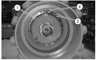
Illustration 2
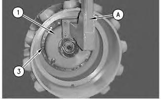
1. Attach Tool (A) on eccentric weight (1). Install guide bolts (3) in the drum. Install the eccentric weight. The weight of the eccentric weight is approximately 330 kg (727 lb).
2. Apply Tooling (B) to the threads of the bolts (2) and install the bolts.
3. Remove Tool (A) from eccentric weight (1). Install remaining bolts (2) .
4. Flush the eccentric weight housing. Refer to Special Instruction, SEHS988-01 for the correct procedure.
5. Fill the eccentric weight housing with oil. The capacity of the eccentric weight housing is approximately 11.83 L (3.12 US gal).
End By: Install the vibratory support. Refer to Disassembly and Assembly, "Vibratory SupportInstall".

Product: VIBRATORY COMPACTOR
Model: CS-433E VIBRATORY COMPACTOR BTT
Configuration: CS/CP-433E Vibratory Compactor BTT00001-UP (MACHINE) POWERED BY 3054C Engine
Disassembly and Assembly
CP-433E, CS-423E and CS-433E
Vibratory Compactors Machine Systems
Media Number -KENR3584-05
Date -01/09/2008
Control Valve (Shift) - Disassemble
SMCS - 5051-015
Disassembly Procedure
Start By:
Updated -29/09/2008
i02070385
a. Remove the control valve (shift). Refer to Disassembly and Assembly, "Control Valve (Shift) - Remove".
Note: Cleanliness is an important factor. Before the disassembly procedure, the exterior of the component should be thoroughly cleaned. This will help to prevent dirt from entering the internal mechanism.
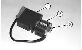
Illustration 1
g00803396
1. Remove nut (3) and coil (2) from valve body (1).
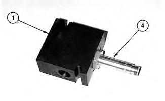
Illustration 2
g00803397
2. Remove valve cartridge (4) from valve body (1).
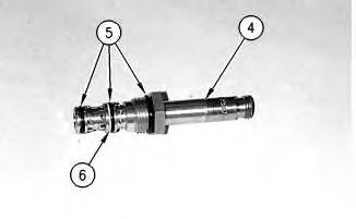
Illustration 3
g00803398
3. Remove O-ring seals (5) and backup ring (6) from valve cartridge (4).
Copyright 1993 - 2024 Caterpillar Inc. All Rights Reserved. Private Network For SIS Licensees. Sun Nov 3 11:39:41 UTC+0530 2024
Product: VIBRATORY COMPACTOR
Model: CS-433E VIBRATORY COMPACTOR BTT
Configuration: CS/CP-433E Vibratory Compactor BTT00001-UP (MACHINE) POWERED BY 3054C Engine
Disassembly and Assembly
CP-433E, CS-423E and CS-433E Vibratory Compactors Machine Systems Media
Eccentric Weight Housing - Assemble
SMCS - 6606-016
Assembly Procedure
Table 1
i02162350
1
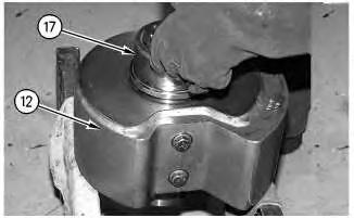
1. Raise the temperature of the inner bearing race (17) to 121 °C (250 °F) and install bearing race (17) onto the shaft of eccentric weight (12). Replace any shims that were removed during disassembly.
2
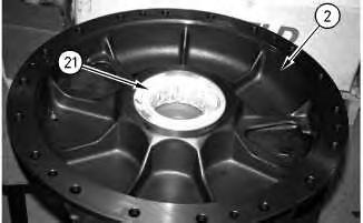
2. Lower the temperature of bearing (21) to -73 °C (-100 °F) and install bearing (21) in cover (2) .
3
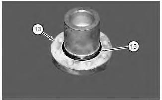
3. Install O-ring seal (15) on shaft (13) .
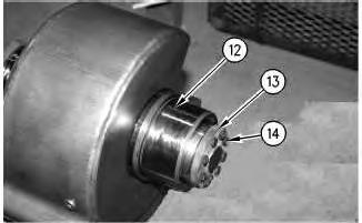
Illustration 4
4. Apply Tooling (G) to the threads of the bolts (14). Install shaft (13) and bolts (14) on eccentric weight (12) .
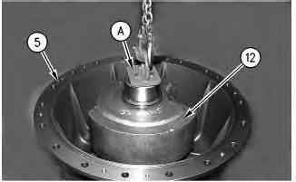
Illustration 5
5. Attach Tooling (A) and install eccentric weight (12) in housing (5). Turn the eccentric weight during installation in order to seat the eccentric weight in the bearing.
6
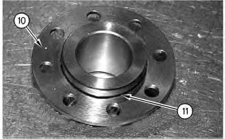
6. Install O-ring seal (11) on flange (10) .
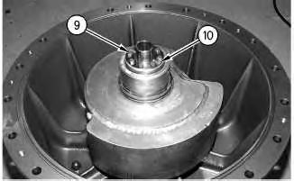
Illustration 7
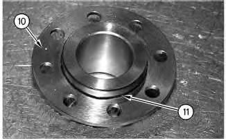
7. Apply Tooling (G) to the threads of the bolts (9). Install flange (10) to eccentric weight with bolts (9) .
8
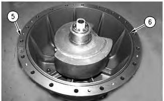
8. Install O-ring seal (6) on housing (5) .
9
10
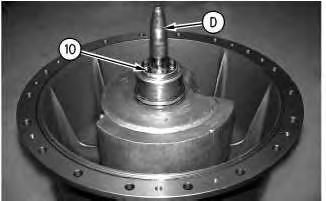
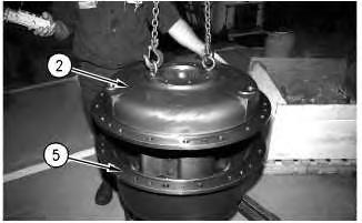
10. Install cover (2) on housing (5). Rotate the cover during installation in order to seat the bearing.
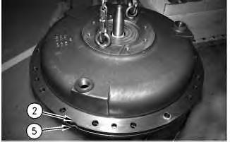
Illustration 11
g00824774
11. Align the notch on cover (2) with the notch on housing (5) .
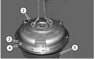
Illustration 12
g00824237
12. Apply Tooling (G) to the threads on the bolts (3). Install bolts (3) and washers (4) .
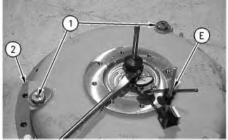
Illustration 13
13. Install drain plugs (1) and cover (2) .
g00824856
14. Use a suitable pry bar and Tooling (E) to check end play. Total end play should not exceed 0.89 ± 0.38 mm (0.035 ± 0.015 inch).
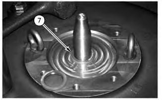
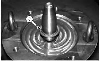
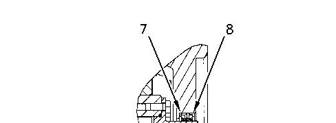
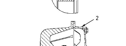
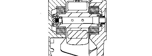

Illustration 16 g00824868
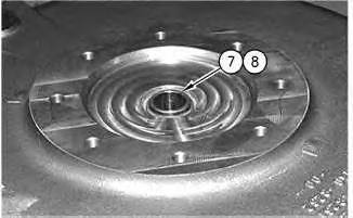
15. Use Tooling (F) to install lip seal (7) and (8) in cover (2) .
End By: Install the eccentric weight housing. Refer to Disassembly and Assembly, "Eccentric Weight Housing - Install".
Copyright 1993 - 2024 Caterpillar Inc. All Rights Reserved.
Network For SIS Licensees.
Sun Nov 3 11:39:25 UTC+0530 2024
Product: VIBRATORY COMPACTOR
Model: CS-433E VIBRATORY COMPACTOR BTT
Configuration: CS/CP-433E Vibratory Compactor BTT00001-UP (MACHINE) POWERED BY 3054C Engine
Disassembly and Assembly
CP-433E, CS-423E and CS-433E
Vibratory Compactors Machine Systems
Media Number -KENR3584-05 Publication Date -01/09/2008 Date Updated -29/09/2008
Control Valve (Shift) - Assemble
SMCS - 5051-016
Assembly Procedure
i02070223
Note: Cleanliness is an important factor. Before assembly, all parts should be thoroughly cleaned in cleaning fluid. Allow the parts to air dry. Wiping cloths or rags should not be used to dry parts. Lint may be deposited on the parts which may cause later trouble. Inspect all parts. If any parts are worn or damaged, use new parts for replacement.
Illustration 1
g00803398
1. Install O-ring seals (5) and backup ring (6) on valve cartridge (4).
Illustration 2
g00803397
2. Install valve cartridge (4) in valve body (1). Tighten the valve cartridge to a torque of 37 N·m (27 lb ft).
Illustration 3
g00803396
3. Install coil (2) and nut (3) on the valve cartridge and valve body (1). Tighten the nut to a torque of 4 N·m (35 lb in).
End By:
a. Install the control valve (shift). Refer to Disassembly and Assembly, "Control Valve (Shift) - Install". Copyright 1993 - 2024 Caterpillar Inc. All Rights Reserved. Private Network For SIS Licensees. Sun Nov 3 11:39:19 UTC+0530 2024
Product: VIBRATORY COMPACTOR
Model: CS-433E VIBRATORY COMPACTOR BTT
Configuration: CS/CP-433E Vibratory Compactor BTT00001-UP (MACHINE) POWERED BY 3054C Engine
Disassembly and Assembly
CP-433E, CS-423E and CS-433E Vibratory Compactors Machine Systems Media
Eccentric Weight Housing - Disassemble
SMCS - 6606-015
Disassembly Procedure
Table 1 Required Tools
i02071648
Start By:
A. Remove the eccentric weight housing. Refer to Disassembly and Assembly, "Eccentric Weight Housing - Remove".
1
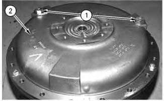
1. Remove drain plugs (1) from cover (2) .
2
2. Remove bolts (3) and washers (4) .
3. Separate cover (2) from housing (5) .
3
4. Remove O-ring seal (6) from housing (5) .
4