

Note: Use Bookmarks panel to navigate

Note: Use Bookmarks panel to navigate
For some reason if link does not work download this pdf and then click

Product: VIBRATORY COMPACTOR
Model: CS-423E VIBRATORY COMPACTOR EAE
Configuration: CS-423E Vibratory Compactor EAE00001-UP (MACHINE) POWERED BY 3054C Engine
Disassembly and Assembly
CP-433E, CS-423E and CS-433E Vibratory Compactors Machine Systems Media
SMCS - 7057-016; 7113-016
Assembly Procedure
Table 1
Required Tools
i02162385
1. Inspect all parts and clean all parts. If any parts are worn or damaged, use new Caterpillar parts for replacement.
2. Inspect all seals. Damaged seals must be replaced. Use new Caterpillar seals for replacement.
1
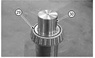
3. Raise the temperature of bearing cone (29) and install bearing cone (29) on shaft (30) .
2
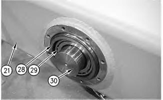
4. Install bearing (29) and shaft (30) in yoke (21) .
5. Install bearing cup (29). Leave the bearing cup out of the yoke approximately 3 mm (0.2 inch).
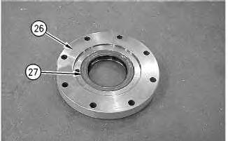
Illustration 3
6. Install lip seal (27) in rear cover (26) .
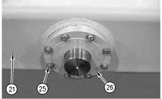
Illustration 4
7. Apply Tooling (A) on the threads of the bolts (25). Install bolts (25) and rear cover (26) on yoke (21). Tighten the bolts to torque of 54 N·m (40 lb ft).
5
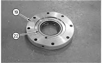
8. Install lip seal (22) in front cover (19) .
6
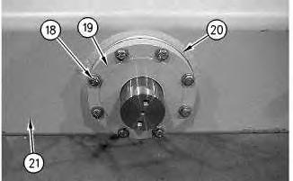
Illustration 7
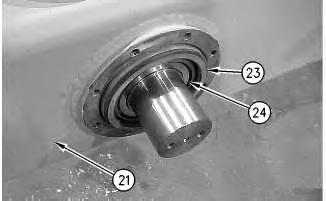
9. Raise the temperature of bearing (24). Install bearing (24) and bearing cup (23) in yoke (21). Leave the bearing cup out of the yoke approximately 3 mm (0.2 inch).
10. Use the following procedure to determine the bearing preload:
Note: The existing shim pack can be used for reference. Use a new shim pack for final installation.
a. Install new shim pack (20), front cover (19), and bolts (18). Tighten the bolts to a torque of 54 N·m (40 lb ft).
b. Measure the rolling torque of the shaft. The correct rolling torque of the shaft is 31 ± 10 N·m (23 ± 7 lb ft).
c. If the rolling torque of the shaft is less than 31 ± 10 N·m (23 ± 7 lb ft), remove the bolts, the front cover, and the proper shims.
d. If the rolling torque of the shaft is more than 31 ± 10 N·m (23 ± 7 lb ft), remove the bolts, the front cover, and the shims. Use a soft hammer and drive the shaft and the bearing cup toward the front of the yoke. This will loosen the bearing preload. Add the proper amount of shims to the shim pack.
e. Reinstall the shims, the front cover, and the bolts. Tighten the bolts to a torque of 54 N·m (40 lb ft).
f. Measure the rolling torque of the shaft. The correct rolling torque of the shaft is 31 ± 10 N·m (23 ± 7 lb ft).
g. After the rolling torque of 31 ± 10 N·m (23 ± 7 lb ft) is achieved, remove the bolts and apply Tooling (A) on the threads of the bolts. Tighten the bolts to a torque of 54 N·m (40 lb ft).
8
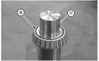
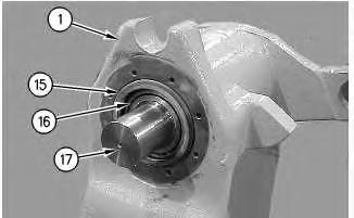
11. Raise the temperature of bearing (16) and install bearing (16) on shaft (17) .
9
12. Install shaft (17) and bearing (16) in hitch (1) .
13. Lower the temperature of bearing cup (15) and install bearing cup (15) in hitch (1). Leave the bearing cup out of the hitch approximately 3 mm (0.2 inch).
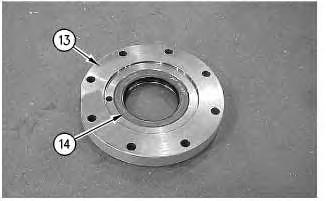
Illustration 10
14. Install lip seal (14) in bottom cover (13) .
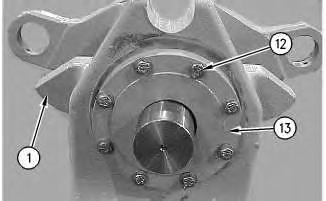
Illustration 11
15. Apply Tooling (A) on the threads of the bolts (12). Install bottom cover (13) and bolts (12) on hitch (1). Tighten the bolts to a torque of 54 N·m (40 lb ft).
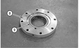
Illustration 12
16. Install lip seal (9) in top cover (8) .
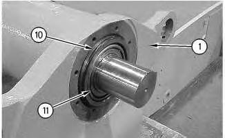
13
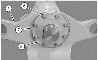
Illustration 14
17. Lower the temperature of bearing cup (10). Install bearing (11) and bearing cup (10) in hitch (1). Leave the bearing cup out of the hitch approximately 3 mm (0.2 inch).
18. Use the following procedure to determine the bearing preload:
Note: The existing shim pack can be used for reference. Use a new shim pack for final installation.
a. Install new shim pack (7), top cover (8), and bolts (6). Tighten the bolts to a torque of 54 N·m (40 lb ft).
b. Measure the rolling torque of the shaft. The correct rolling torque of the shaft is 31 ± 10 N·m (23 ± 7 lb ft).
c. If the rolling torque of the shaft is less than 31 ± 10 N·m (23 ± 7 lb ft), remove the eight bolts, the top cover, and the proper shims.
d. If the rolling torque of the shaft is more than 31 ± 10 N·m (23 ± 7 lb ft), remove the bolts, the top cover, and the shims. Use a soft hammer and drive the shaft and the
bearing cup toward the front of the yoke. This will loosen the bearing preload. Add the proper amount of shims to the shim pack.
e. Reinstall the shims, the top cover, and the bolts. Tighten the bolts to a torque of 54 N·m (40 lb ft).
f. Measure the rolling torque of the shaft. The correct rolling torque of the shaft is 31 ± 10 N·m (23 ± 7 lb ft).
g. After the rolling torque of 31 ± 10 N·m (23 ± 7 lb ft) is achieved, remove the bolts and apply Tooling (A) on the threads of the bolts. Tighten the bolts to a torque of 54 N·m (40 lb ft).
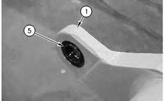
Illustration 15
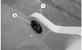
19. Install the bearings (5) in hitch (1) .
g00855264
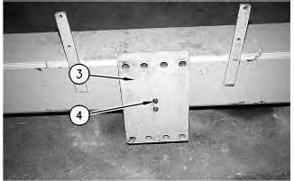
Illustration 16
g00855261
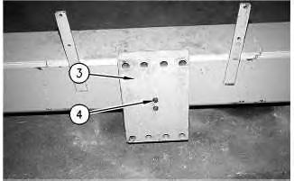
20. Attach a suitable lifting device to end plate (3). Install the end plate on the end of the shaft and install two bolts (4). The weight of the end plate is approximately 38 kg (84 lb).
17
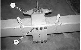
21. Attach a suitable lifting device to hitch (1). Install the hitch and bolts (2). The weight of the hitch is 150 kg (331 lb).
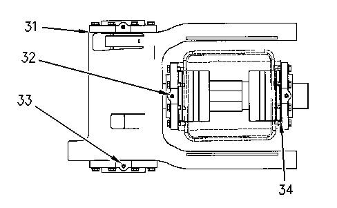
Illustration 18
22. After the yoke and the hitch has been installed, the cavities must be filled with grease by using the following procedure:
a. Remove plug (32) and install Tooling (B). Fill the cavity with Tooling (C) until the grease comes out of seal (31) .
b. Remove plug (33) and install Tooling (B). Fill the cavity with Tooling (C) until the grease comes out of seal (34) .
c. After both cavities have been filled with grease, remove both of the fittings and install plugs (32) and (33) .
End By: Install the articulating and the oscillating hitch. Refer to Disassembly and Assembly, "Articulating and Oscillating Hitch - Install".
Copyright 1993 - 2025 Caterpillar Inc. All Rights Reserved. Private Network For SIS Licensees.
Tue Mar 18 02:01:53 UTC+0530 2025
Product: VIBRATORY COMPACTOR
Model: CS-423E VIBRATORY COMPACTOR EAE
Configuration: CS-423E Vibratory Compactor EAE00001-UP (MACHINE) POWERED BY 3054C Engine
Disassembly and Assembly
CP-433E, CS-423E and CS-433E Vibratory Compactors Machine Systems
SMCS - 7057-015; 7113-015
Disassembly Procedure
Start By:
A. Remove the articulating and oscillating hitch. Refer to Disassembly and Assembly, "Articulating and Oscillating Hitch - Remove".
1 g00855260
1. Attach a suitable lifting device to hitch (1), as shown. Remove bolts (2) and remove the hitch from the yoke. The weight of the hitch is approximately 150 kg (331 lb).
2
2. Attach a suitable lifting device to end plate (3). Remove bolts (4) and remove the end plate from the shaft. The weight of the end plate is approximately 38 kg (84 lb).
3
3. Remove bearings (5) from hitch (1) .
4
4. Remove bolts (6), shims (7), and top cover (8) from hitch (1) .
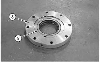
Illustration 5
Note: Identify the direction of lip seal (9) .
5. Remove lip seal (9) from top cover (8) .
Illustration 6
6. Use a soft faced hammer to drive out the shaft in order to remove the bearing cup (10). Remove bearing cup (10) and bearing (11) from hitch (1) .
7
7. Remove bolts (12) and bottom cover (13) from hitch (1) .
Illustration 8
Note: Identify the direction of lip seal (14) .
8. Remove lip seal (14) from bottom cover (13) .
9
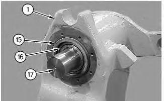
9. Use a soft faced hammer to drive out the shaft (17) in order to remove the bearing cup (15). Remove bearing cone (16) and shaft (17) from hitch (1) .
10
10. Remove bearing cone (16) from shaft (17) .
11
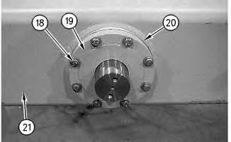
11. Remove bolts (18), front cover (19), and shims (20) from yoke (21) .
12
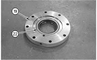
Note: Identify the direction of lip seal (22) in front cover (19) .
12. Remove lip seal (22) from front cover (19) .
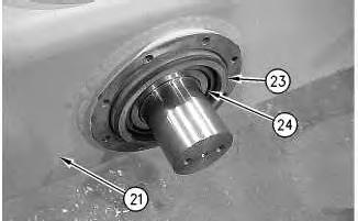
13
13. Use a soft faced hammer to drive out the shaft and the bearing (24). Remove bearing cup (23) from yoke (21) .
Illustration 14 g00855277
14. Remove bolts (25) and rear cover (26) from yoke (21) .
Illustration 15
g00855278
Note: Identify the direction of lip seal (27) in rear cover (26) .
15. Remove lip seal (27) from rear cover (26) .
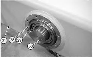
Illustration 16
g00855280
16. Use a soft faced hammer to drive out shaft (30) and bearing cone (29). Remove bearing cup (28), bearing cone (29), and shaft (30) from yoke (21) .
17 g00855282 17. Remove bearing cone (29) from shaft (30) .
Copyright 1993 - 2025 Caterpillar Inc.
All Rights Reserved.
Private Network For SIS Licensees.
Tue Mar 18 02:02:06 UTC+0530 2025
Product: VIBRATORY COMPACTOR
Model: CS-423E VIBRATORY COMPACTOR EAE
Configuration: CS-423E Vibratory Compactor EAE00001-UP (MACHINE) POWERED BY 3054C Engine
Disassembly and Assembly
CP-433E, CS-423E and CS-433E
Vibratory Compactors Machine Systems
SMCS - 7057-012; 7113-012
Installation Procedure Table 1 Required Tools
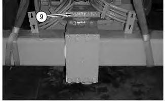
Illustration 1
1. Attach a suitable lifting device and Tooling (B) to the yoke. Install the yoke and the oscillating hitch as a unit and install caps and bolts (9). The weight of the yoke and the oscillating hitch is approximately 825 kg (1820 lb).
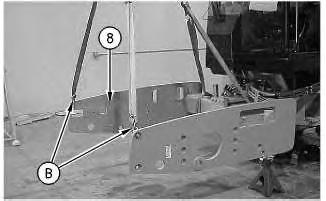
2
3
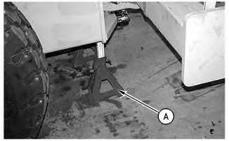
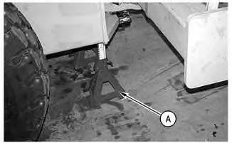
2. Raise the machine and remove Tooling (A) from the machine frame. Install Tooling (A) under the yoke, as shown. Lower the yoke. Remove the lifting device and Tooling (B) from the yoke.
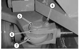
3. Install steering cylinder (6), pin assembly (5), and bolt (4) on oscillating hitch (7) on both sides of the machine.
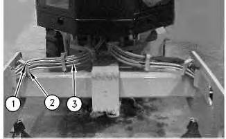
Illustration 5
g00833835
4. Connect hose assemblies (3), hose guards (1), and bolts (2) .
End By: Install the drum. Refer to Disassembly and Assembly, "Drum - Install".
Copyright 1993 - 2025 Caterpillar Inc. All Rights Reserved. Private Network For SIS Licensees.
Tue Mar 18 02:01:39 UTC+0530 2025
Product: VIBRATORY COMPACTOR
Model: CS-423E VIBRATORY COMPACTOR EAE
Configuration: CS-423E Vibratory Compactor EAE00001-UP (MACHINE) POWERED BY 3054C Engine
Disassembly and Assembly
CP-433E, CS-423E and CS-433E Vibratory Compactors Machine Systems Media Number -KENR3584-05
i02069582
Articulating and Oscillating Hitch - Remove
SMCS - 7057-011; 7113-011
Removal Procedure
Table 1 Required Tools
Start By:
A. Remove the drum. Refer to Disassembly and Assembly, "Drum - Remove".
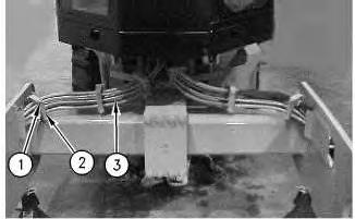
1. Remove bolts (2) and hose guards (1). Move hose assemblies (3) out of the way.
2
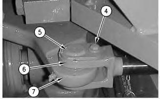
2. Remove bolt (4), pin assembly (5), and steering cylinder (6) from oscillating hitch (7) on both sides of the machine.
3
For some reason if link does not work download this pdf and then click