DOWNLOAD LINK
For some reason if link does not work download this pdf and then click
Product: VIBRATORY COMPACTOR
Model: CS-323C VIBRATORY COMPACTOR DAR
Configuration: CS/CP-323C Vibratory Compactor DAR00001-UP (MACHINE) POWERED BY 3054B Engine
Disassembly and Assembly
CP-323C and CS-323C Paving Compactors Engine Supplement
Media Number -KENR3693-01
Publication Date -01/08/2004 Date Updated -03/08/2004
i02084315
Engine - Install
SMCS - 1000-012
Installation Procedure Table 1
Required Tools
Illustration 1
g01063093
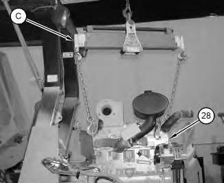
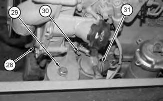
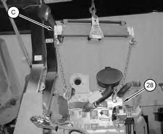
1. Attach Tooling (C) and a suitable lifting device to engine (28) .
Illustration 2
g01063085
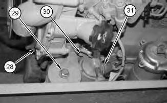
2. Install engine (28) in the machine and install bolts (29). The weight of engine (28) is approximately 680 kg (1500 lb).
3. Apply Tooling (D) to bolts (30). Install the gasket, engine oil filter assembly (31), and bolts (30) on the engine.
Illustration 3
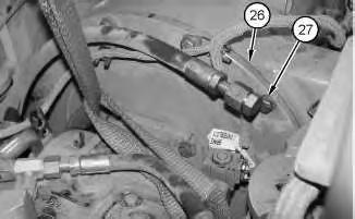
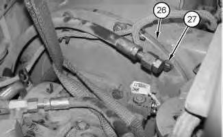
4. Install bolts (27).
Illustration 4
g01062661
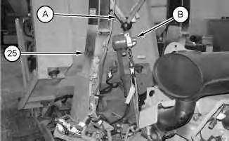
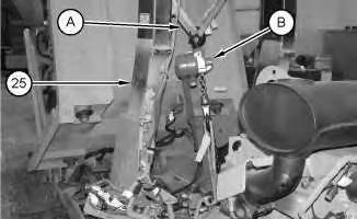
5. Remove Tooling (A) and (B) from ROPS (25) .
Illustration 5
g01063363
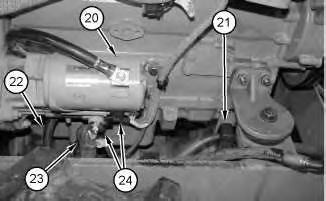
6. Connect harness assemblies (24) to electric starting motor (20) and install cable straps.
g01062658
7. Install the nut and cable assembly (23) on electric starting motor (20) .
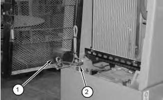
8. Install clamp (21) on the bracket.
9. Install cable assembly (22) on the engine.
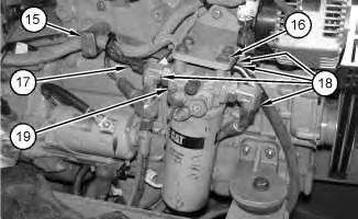
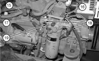
10. Install hydraulic oil filter assembly (19) on the bracket and install bolts (16) .
11. Connect hose assemblies (18) on hydraulic oil filter assembly (19) .
12. Connect harness assembly (17) to hydraulic oil filter assembly (19) .
13. Install clamp (15) .
7
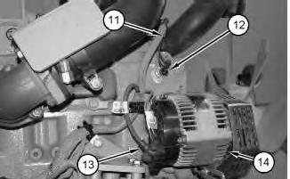
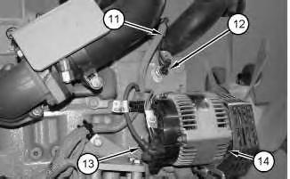
14. Connect harness assemblies (13) to alternator (14) and install cable straps.
15. Connect harness assembly (11) to engine temperature sensor (12) and install the cable straps.
Illustration 6
g01062576
Illustration
g01062569
Illustration 8
g01063326
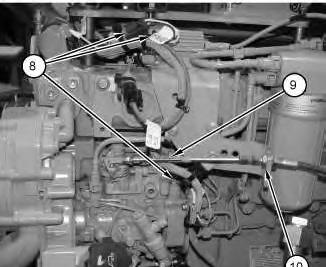
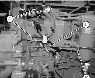
16. Install cable (9) on the bracket and tighten jam nut (10). Attach cable (9) to the engine.
17. Connect harness assemblies (8) and attach cable straps.
Illustration 9
g01063301
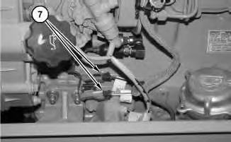
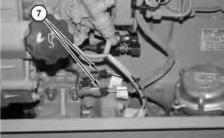
18. Connect harness assemblies (7) to the engine.
10
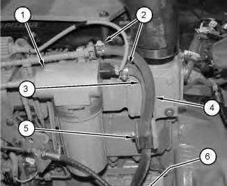
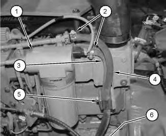
19. Install hoses (3) and (4) on fuel filter assembly (1) and tighten clamps (2) .
20. Install hoses (3) and (4) on the engine and install clamps (5) and (6) .
End By:
a. Install the radiator. Refer to Disassembly and Assembly, "Radiator - Remove and Install".
b. Install the engine oil cooler. Refer to Disassembly and Assembly, "Hydraulic Oil CoolerRemove and Install".
c. Install the hydraulic tank. Refer to Disassembly and Assembly, "Hydraulic Oil TankRemove and Install".
d. Install air cleaner. Refer to Disassembly and Assembly, "Air Cleaner - Remove and Install".
Fri Aug 23 16:25:12 UTC+0530 2024
Product: VIBRATORY COMPACTOR
Model: CS-323C VIBRATORY COMPACTOR DAR
Configuration: CS/CP-323C Vibratory Compactor DAR00001-UP (MACHINE) POWERED BY 3054B Engine
Disassembly and Assembly
CP-323C and CS-323C Paving Compactors Engine Supplement Media
Engine - Remove
SMCS - 1000-011
Removal Procedure
Table 1
Required Tools
- 16 THD)
Start By:
A. Remove the hydraulic oil cooler. Refer to Disassembly and Assembly, "Hydraulic Oil Cooler - Remove and Install".
B. Remove the hydraulic oil tank. Refer to Disassembly and Assembly, "Hydraulic Oil TankRemove and Install".
C. Remove the air cleaner. Refer to Disassembly and Assembly, "Air Cleaner - Remove and Install".
D. Remove the radiator. Refer to Disassembly and Assembly, "Radiator - Remove and Install".
Note: SERVICE DATA: TOOLING (ZZ) WILL NOT BE IDENTIFIED IN PHOTOGRAPHS IN THE REMOVAL OR THE INSTALLATION. THIS TOOLING IS SHOWN IN ORDER TO ASSIST THE EXPERIENCED SERVICEMAN.
This is the sample of the sample click on the download link for complete manual
DOWNLOAD LINK
For some reason if link does not work download this pdf and then click
Hot engine components can cause injury from burns. Before performing maintenance on the engine, allow the engine and the components to cool.
NOTICE
Care must be taken to ensure that fluids are contained during performance of inspection, maintenance, testing, adjusting and repair of the product. Be prepared to collect the fluid with suitable containers before opening any compartment or disassembling any component containing fluids.
Refer to Special Publication, NENG2500, "Caterpillar Tools and Shop Products Guide" for tools and supplies suitable to collect and contain fluids on Caterpillar products.
Dispose of all fluids according to local regulations and mandates.
Note: Put identification marks on all hoses, on all hose assemblies, on all wires, and on all tube assemblies for installation purposes. Plug all hose assemblies and all tube assemblies. This helps to prevent fluid loss, and this helps to keep contaminants from entering the system.
1. Loosen clamps (2) and remove hoses (3) and (4) from fuel filter assembly (1) .
2. Remove clamps (5) and (6) and move hoses (3) and (4) away from the engine.
Illustration 2
g01063301
3. Disconnect harness assemblies (7) from the engine.
Illustration 3
g01063326
4. Remove cable straps and disconnect harness assemblies (8) .
5. Remove the cable (9) from the engine. Loosen jam nut (10) and move cable (9) out of the way.
Illustration 4
6. Remove the cable straps and disconnect harness assembly (11) from engine temperature sensor (12) .
7. Remove the cable straps and disconnect harness assemblies (13) from alternator (14) .
Illustration 5
8. Remove clamp (15) .
g01062576
9. Disconnect harness assembly (17) from hydraulic oil filter assembly (19) .
10. Remove hose assemblies (18) from hydraulic oil filter assembly (19) .
11. Remove bolts (16) and remove hydraulic oil filter assembly (19) .
g01062569
12. Remove cable assembly (22) from the engine.
13. Remove cable straps and disconnect harness assemblies (24) from electric starting motor (20) .
14. Remove the nut and cable assembly (23) from electric starting motor (20) .
15. Remove clamp (21) from the bracket.
Illustration 6
g01063363
Illustration 7
g01062661
Illustration 8 g01062658
16. Attach Tooling (A) to ROPS (25), as shown. Attach Tooling (B) to Tooling (A). Attach the other end of Tooling (B) to propel pump and adapter plate (26) .
17. Remove bolts (27) .
Illustration 9
18. Attach Tooling (C) to engine (28) .
10
19. Remove bolts (30) and remove engine oil filter assembly (31) and the gasket from engine (28) .
g01063093
Illustration
g01063085
20. Remove bolts (29) and remove engine (28) from the machine. The weight of the engine is approximately 680 kg (1500 lb).
Copyright 1993 - 2024 Caterpillar Inc. All Rights Reserved. Private Network For SIS Licensees.
Fri Aug 23 16:24:57 UTC+0530 2024
Product: VIBRATORY COMPACTOR
Model: CS-323C VIBRATORY COMPACTOR DAR
Configuration: CS/CP-323C Vibratory Compactor DAR00001-UP (MACHINE) POWERED BY 3054B Engine
Disassembly and Assembly
CP-323C and CS-323C Paving Compactors Engine Supplement
Media Number -KENR3693-01
Publication Date -01/08/2004
Radiator - Remove and Install
SMCS - 1353-010
Removal Procedure
Table 1
Required Tools
Tool
A 138-7573 Link Bracket 2
Start By:
Date Updated -03/08/2004
A. Remove the engine enclosure. Refer to Disassembly and Assembly, "Engine Enclosure (Hood) - Remove and Install".
B. Remove the hydraulic oil cooler. Refer to Disassembly and Assembly, "Hydraulic Oil Cooler - Remove and Install".
Note: Put identification marks on all hoses, on all hose assemblies, on all wires, and on all tube assemblies for installation purposes. Plug all hose assemblies and all tube assemblies. This helps to prevent fluid loss, and this helps to keep contaminants from entering the system.
NOTICE
Care must be taken to ensure that fluids are contained during performance of inspection, maintenance, testing, adjusting and repair of the product. Be prepared to collect the fluid with suitable containers before opening any compartment or disassembling any component containing fluids.
i02066783
Refer to Special Publication, NENG2500, "Caterpillar Tools and Shop Products Guide" for tools and supplies suitable to collect and contain fluids on Caterpillar products.
Dispose of all fluids according to local regulations and mandates.
At operating temperature, the engine coolant is hot and under pressure.
Steam can cause personal injury.
Check the coolant level only after the engine has been stopped and the fill cap is cool enough to touch with your bare hand.
Remove the fill cap slowly to relieve pressure.
Cooling system conditioner contains alkali. Avoid contact with the skin and eyes to prevent personal injury.
1. Drain the coolant from the cooling system into a suitable container for storage or disposal. The capacity of the cooling system is approximately 20.8 L (5.5 US gal). Refer to Operation and Maintenance Manual, "Cooling System Coolant (ELC) - Change" for the correct procedure.
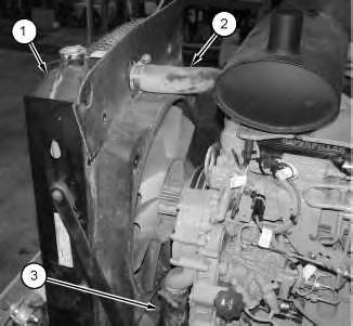
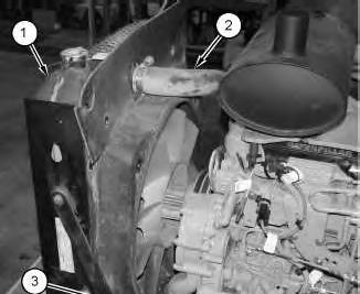
2. Loosen the hose clamp and remove hose (3) from the bottom of radiator (1) .
3. Loosen the hose clamp and remove hose (2) from the top of radiator (1) .
Illustration 2
g01059039
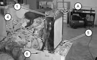
4. Attach a suitable lifting device and Tooling (A) to the radiator. Remove two bolts (6) that secure braces (4) on each side of the radiator to the machine. Remove bolts (5) from the mount. Remove radiator (1). The weight of the radiator is approximately 30 kg (65 lb).
Installation Procedure
Table 2
Required Tools
Tool Part Number Part
A 138-7573 Link Bracket 2
Illustration 3
g01059039
1. Attach a suitable lifting device and Tooling (A) to the radiator. Install radiator (1). The weight of the radiator is approximately 30 kg (65 lb).
2. Install bolts (5) in the mount.
3. Install bolts (6) that secure braces (4) on each side of the machine.
Illustration 4 g01059011
4. Install hose (3) on the top of radiator (1) and tighten the hose clamp.
5. Install hose (2) on the bottom of radiator (1) and tighten the hose clamp.
6. Fill the cooling system with coolant. The capacity of the cooling system is 20.8 L (5.5 US gal). Refer to Operation and Maintenance Manual, "Cooling System Coolant (ELC)Change" for the correct procedure.
7. Secure the filler cap on the radiator.
End By:
a. Install the hydraulic oil cooler. Refer to Disassembly and Assembly, "Hydraulic Oil Cooler - Remove and Install".
b. Install the engine enclosure. Refer to Disassembly and Assembly, "Engine Enclosure (Hood) - Remove and Install".
1993 - 2024 Caterpillar Inc.
SIS
Fri Aug 23 16:24:46 UTC+0530 2024
Product: VIBRATORY COMPACTOR
Model: CS-323C VIBRATORY COMPACTOR DAR
Configuration: CS/CP-323C Vibratory Compactor DAR00001-UP (MACHINE) POWERED BY 3054B Engine
Disassembly and Assembly
CP-323C and CS-323C Paving Compactors Engine Supplement
Hydraulic Oil Cooler - Remove and Install
SMCS - 1374-010
Removal Procedure
Start By:
A. Remove the engine enclosure. Refer to Disassembly and Assembly, "Engine Enclosure (Hood) - Remove and Install" for the proper removal procedure.
Personal injury can result from hydraulic oil pressure and hot oil.
Hydraulic oil pressure can remain in the hydraulic system after the engine has been stopped. Serious injury can be caused if this pressure is not released before any service is done on the hydraulic system.
Make sure all of the work tools have been lowered to the ground, and the oil is cool before removing any components or lines. Remove the oil filler cap only when the engine is stopped, and the filler cap is cool enough to touch with your bare hand.
NOTICE
Care must be taken to ensure that fluids are contained during performance of inspection, maintenance, testing, adjusting and repair of the product. Be prepared to collect the fluid with suitable containers before opening any compartment or disassembling any component containing fluids.
i02148509
Refer to Special Publication, NENG2500, "Caterpillar Tools and Shop Products Guide" for tools and supplies suitable to collect and contain fluids on Caterpillar products.
Dispose of all fluids according to local regulations and mandates.
NOTICE
Keep all parts clean from contaminants.
Contamination of the hydraulic system with foreign material will reduce the service life of the hydraulic system components.
To prevent contaminants from entering the hydraulic system, always plug or cap the lines, fittings, or hoses as they are disconnected. Cover any disassembled components and clean them properly before assembly.
Clean the hydraulic system properly after any major component exchange or especially after a component failure, to remove any contamination.
Note: Put identification marks on all lines, on all hoses, on all wires, and on all tubes for installation purposes. Plug all lines, all hoses and all tubes. This helps to prevent fluid loss and this helps to keep contaminants from entering the system.
1. Drain the hydraulic oil from the hydraulic oil tank. The capacity of the hydraulic oil tank is approximately 75.5 L (19.9 US gal). Refer to Operation and Maintenance Manual, "Hydraulic System Oil - Change" for the proper draining procedure.
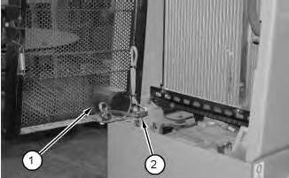
2. Disconnect harness assembly (2) from the backup alarm (1). Remove the cable straps that secure the harness assembly to the grill. Position the harness assembly out of the way.
3
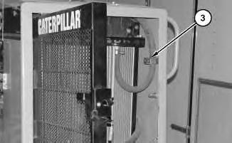
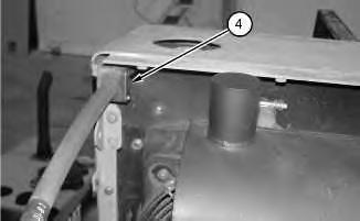
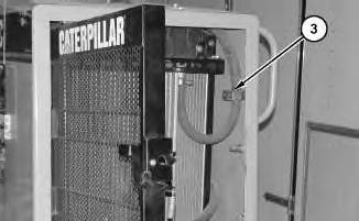
3. Remove clamps (3) and (4) .
Illustration 2
g01061230
Illustration
g01061207
4
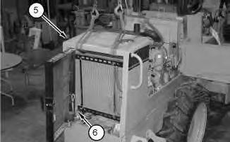
4. Attach a suitable lifting device to radiator guard (5). Remove bolts (6) that secure radiator guard (5) to the machine frame, and remove the radiator guard and the grill as a unit. The weight of the radiator guard and grill as a unit is approximately 70 kg (154 lb).
5
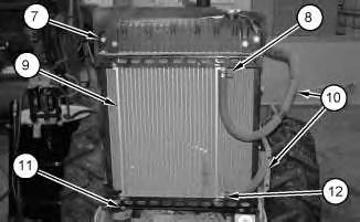
5. Loosen clamps (8) and (12). Remove hoses (10) from hydraulic oil cooler (9) .
6. Remove bolts (11) that secure the bottom of the hydraulic oil cooler to the radiator bracket.
7. Support the hydraulic oil cooler. Remove remaining bolts (7) that secure hydraulic oil cooler (9) to the radiator bracket. Remove the hydraulic oil cooler.
Installation Procedure
NOTICE
Care must be taken to ensure that fluids are contained during performance of inspection, maintenance, testing, adjusting and repair of the product. Be prepared to collect the fluid with suitable containers before opening any compartment or disassembling any component containing fluids.
Refer to Special Publication, NENG2500, "Caterpillar Tools and Shop Products Guide" for tools and supplies suitable to collect and contain fluids on Caterpillar products.
Dispose of all fluids according to local regulations and mandates.
Illustration
g01057319
6
1. Position hydraulic oil cooler (9) on the radiator bracket. Install the top bolts (7) .
2. Install bolts (11) that secure the bottom of the hydraulic oil cooler to the radiator bracket.
3. Install hoses (10) on hydraulic oil cooler (9) and tighten clamps (8) and (12) .
7
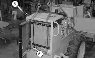
4. Attach a suitable lifting device to radiator guard (5). Position the radiator guard and the grill as a unit. Install bolts (6). The weight of the radiator guard and grill as a unit is approximately 70 kg (154 lb).
Illustration
g01057319
Illustration
g01061209
8
Illustration 9
5. Install clamps (3) and (4) .
10
6. Connect harness assembly (2) to the backup alarm (1). Secure the harness assembly with cable straps.
Illustration
g01061207
g01061230
Illustration
g01061201
This is the sample of the manual click on the download link for complete manual