



Product: VIBRATORY COMPACTOR
Model: CP-533D VIBRATORY COMPACTOR 6AZ
Configuration: CP-533D CS-533D Vibratory Compactor 6AZ00001-UP (MACHINE) POWERED BY 3116 Engine
Disassembly and Assembly 3116 ENGINE SUPPLEMENT FOR CS-531D, CP-533D AND CS-533D VIBR
Media Number -KENR3523-00 Publication Date -01/08/2000
Air Cleaner
SMCS - 1051-010
Remove & Install Air Cleaner
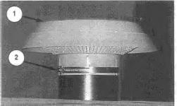
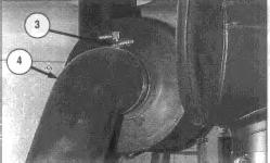
Date Updated -10/10/2001
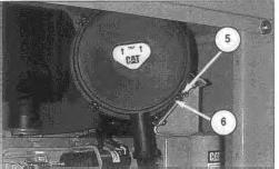
3. Loosen four clamps (5), and remove cover (6) from the air cleaner housing. Remove the seal from the cover. Check the seal for damage or wear and replace if necessary.
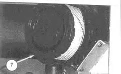
4. Remove primary element (7) from the air cleaner housing.
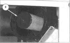
5. Remove secondary element (8) from the air cleaner housing.
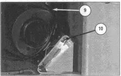
6. Remove four bolts (10), and remove air cleaner housing (9) from the bracket.
NOTE: For installation of the air cleaner, reverse the removal steps. Thu Jun 6 23:46:09 UTC+0530 2024
This is the sample of the manual click on the download link for complete manual
DOWNLOAD LINK
For some reason if link does not work download this pdf and then click
Product: VIBRATORY COMPACTOR
Model: CP-533D VIBRATORY COMPACTOR 6AZ
Configuration: CP-533D CS-533D Vibratory Compactor 6AZ00001-UP (MACHINE) POWERED BY 3116 Engine
Disassembly and Assembly 3116 ENGINE SUPPLEMENT FOR CS-531D, CP-533D AND CS-533D VIBR
Media Number -KENR3523-00 Publication Date -01/08/2000
Alternator Belt
SMCS - 1357-010
Remove & Install Alternator Belt
1. Move the disconnect switch to the OFF position.
2. Open the left side panel or open the engine enclosure.
Date Updated -10/10/2001
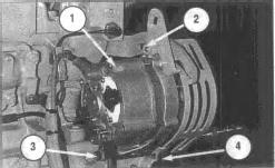
3. Loosen bolts (2) and (3), and move alternator (1) towards the engine to loosen the belt. Remove alternator belt (4).
NOTE: To install the alternator belt, reverse the removal steps.
NOTE: During installation, see the Operation And Maintenance Manual, Form No. KEBU7506, for the proper belt tension.
Copyright 1993 - 2024 Caterpillar Inc. All Rights Reserved. Private Network For SIS Licensees. Thu Jun 6 23:47:57 UTC+0530 2024
Product: VIBRATORY COMPACTOR
Model: CP-533D VIBRATORY COMPACTOR 6AZ
Configuration: CP-533D CS-533D Vibratory Compactor 6AZ00001-UP (MACHINE) POWERED BY 3116 Engine
Disassembly and Assembly 3116 ENGINE SUPPLEMENT FOR CS-531D, CP-533D AND CS-533D VIBR
Media Number -KENR3523-00 Publication Date -01/08/2000 Date Updated -10/10/2001
Alternator
SMCS - 1405-010
Remove & Install Alternator
1. Move the disconnect switch to the OFF position.
2. Open the left side panel or open the engine enclosure.
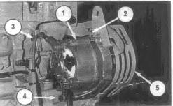
3. Remove three wires (3) from alternator (1).
4. Loosen bolts (2) and (4). Move alternator toward the engine, and remove the alternator belt.
5. Remove bolts (2) and (4), and remove alternator (1) and guard (5) from the engine.
NOTE: To install the alternator, reverse the removal steps.
NOTE: During installation, see the Operation And Maintenance Manual, Form No. KEBU7506, for the proper belt tension.
Copyright 1993 - 2024 Caterpillar Inc. All Rights Reserved.
Private Network For SIS Licensees. Thu Jun 6 23:47:45 UTC+0530 2024
Product: VIBRATORY COMPACTOR
Model: CP-533D VIBRATORY COMPACTOR 6AZ
Configuration: CP-533D CS-533D Vibratory Compactor 6AZ00001-UP (MACHINE) POWERED BY 3116 Engine
Disassembly and Assembly 3116 ENGINE SUPPLEMENT FOR CS-531D, CP-533D AND CS-533D VIBR
Media Number -KENR3523-00 Publication Date -01/08/2000 Date Updated -10/10/2001
Engine (CP-533D & CS-533D)
SMCS - 1000-010
Remove & Install Engine
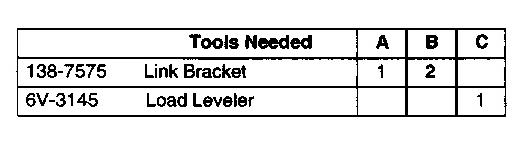
Start By:
a. open engine enclosure or remove hood
b. *tilt operators platform
*This procedure is in the Machine Systems Disassembly & Assembly module, Form No. KENR3529.
1. Move the disconnect switch to the OFF position.
Personal injury can result from hot coolant, steam, and alkali.
At operating temperature, the engine coolant is hot and under pressure. Steam can cause personal injury. The radiator and all lines to heaters or the engine contain hot coolant or steam. Any contact can cause severe burns.
Remove filler cap from the radiator slowly to relieve pressure only when the engine is stopped and radiator cap is cool enough to touch with your bare hands.
Do not attempt to tighten hose connections when the coolant is hot, the hose can come off causing burns.
Cooling System Conditioner contains alkali. Avoid contact with skin and eyes.
2. Drain the radiator. The capacity of the cooling system is 30.0 liters (8 U. S. gallons). Refer to the Operation and Maintenance Manual, Form No. KEBU7506, for the correct procedure.
Personal injury can result from hydraulic oil pressure and hot oil.
Hydraulic oil pressure can remain in the hydraulic system after the engine has been stopped. Serious injury can be caused if this pressure is not released before any service is done on the hydraulic system.
Make sure all of the attachments have been lowered, oil is cool before removing any components or lines. Remove the oil filler cap only when the engine is stopped, and the filler cap is cool enough to touch with your bare hand.
NOTICE
Care must be taken to ensure that fluids are contained during performance of inspection, maintenance, testing, adjusting, and repair of the product. Be prepared to collect the fluid with suitable containers before opening any compartment or disassembling any component containing fluids.
Refer to Special Publication, NENG2500, "Caterpillar Tools and Shop Products Guide" for tools and supplies suitable to collect and contain fluids on Caterpillar products.
Dispose of all fluids according to local regulations and mandates.
NOTE: Identify all hydraulic lines as they are removed for reinstallation purposes. Cap and plug all lines and fittings to prevent any contaminants from entering the system.
3. Release the pressure in the hydraulic system by slowly loosening the fill cap located on the top of the hydraulic oil tank.
4. Drain the hydraulic oil from the hydraulic oil tank. The capacity of the hydraulic oil tank is 80 liters (21.1 U. S. gallons). Refer to the Operation and Maintenance Manual, Form No. KEBU7506, for the correct procedure.
NOTE: Steps 5 through 10 are for machines equipped with a hood.
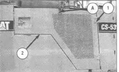
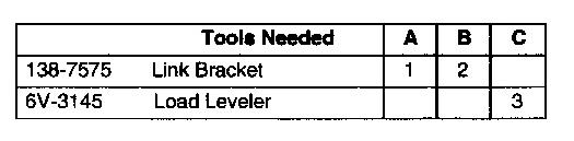
5. Attach Tool (A) to left side panel (2). Remove four bolts (1) and remove the left side panel. The weight of the left side panel is 29 kg (64 lb). Note: During installation, shim the left side panel to 5 mm (0.197 inch).
6. Repeat Step 5 for the right side panel.
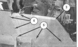
NOTE: The wheel assembly has been removed for photographic purposes only.
7. Remove bolts (4) from left side panel (3).
8. Loosen bolts (5) and remove left side panel (3).
9. Repeat steps 7 and 8 for the right side panel.
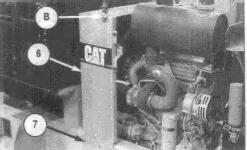
10. Attach Tooling (B) and a suitable hoist to support assembly (6). Loosen six bolts (7) and remove the support assembly from the machine. The weight of the support assembly is 26 kg (58 lb).
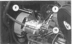
NOTE: Use steps 11 through 14 if the machine is equipped with air conditioning.
11. Disconnect two electrical connectors (9).
12. Remove the bolt from air conditioner compressore strap (8).
13. Remove bolt (10) and remove air conditioning unit. Move the air conditioning unit out of the way.
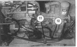
14. Remove three clamps (11) from two hose assemblies (12).
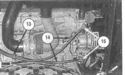
NOTE: Use steps 15 through 19 if the machine is equipped with a heater.
15. Turn shut off valves (15) off.
16. Disconnect two hose assemblies (14) from shut off valves (15). Plug hose assemblies immediately.
17. Remove clamp (13) from two hose assemblies (14).
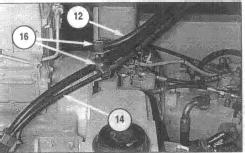
18. Remove clamps (16) from two hose assemblies (12) and (14).
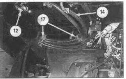
19. Remove clamps (17) from two hose assemblies (12) and (14).
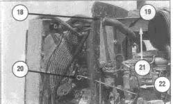
20. Disconnect air indicator tube (18) from the hydraulic oil tank frame.
21. Loosen the clamp, and remove coolant hose (19) from the top of the hydraulic oil tank frame.
22. Remove the three bolts that fasten air cleaner bracket (21) to the hydraulic oil tank frame.
23. Remove oil level indicator (20).
24. Disconnect two fuel lines (22) from the engine. Cap and plug immediately.
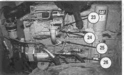
25. Disconnect three electrical connectors (23).
26. Disconnect three wires (24) from the fuel shutoff solenoid.
27. Remove the cable ties that fasten wiring harness (25) to the engine. Move the wiring harness out of the way.
28. Disconnect four hose assemblies (26) from the steering pump. Cap and plug immediately.
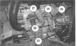
29. Disconnect wire (27) from the engine heater.
30. Disconnect electrical connector (28).
31. Disconnect two wires (29) from the alternator.
32. Remove the cable ties that fasten wiring harness (30) to the engine. Move the wiring harness out of the way.
33. Loosen the clamp, and remove coolant hose (31) from the engine.
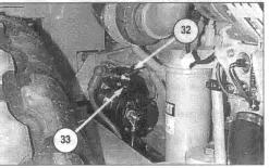
34. Remove five wires (32) from the starter.
35. Remove the nut, and remove cover (33) from the starter.
36. Remove the remaining two wires from the starter.
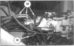
37. Disconnect hose assemblies (34) and (35) from the vibratory pump. Cap and plug immediately.
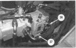
38. Disconnect two hose assemblies (36) from the vibratory pump. Cap and plug immediately.
39. Disconnect two electrical connectors (37).
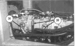
40. Disconnect hose assemblies (38) and (39) from the propel pumps. Cap and plug immediately.
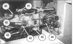
41. Disconnect hose assemblies (40), (43), (44) and (46) from the propel pumps. Cap and plug immediately.
42. Remove the cotter pin and pin that fastens control cable (45) to the propel pump. Loosen the jam nut and remove control cable (45) from the bracket. Move the control cable out of the way.
43. Mark electrical connectors (41) for assembly purposes. Remove the screws that fasten electrical connectors (41) to the control valves on the propel pumps. Remove the electrical connectors from the propel pumps.
44. Remove the cable ties that fasten wiring harness (42) to the pumps. Move the wiring harness out of the way.
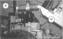
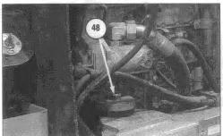
45. Attach a Tooling (A) and a hoist to the engine as shown. Remove four mounting bolts (48), and remove engine (47) and the pumps as a unit from the machine. The weight of the engine and pumps as a unit is approximately 726 kg (1600 lb).
NOTE: For the installation of the engine, reverse the removal steps.
NOTE: After the engine has been installed, fill the cooling system with coolant to the correct level. Fill the hydraulic oil system with hydraulic oil to the correct level. See the Operation & Maintenance Manual, Form No. KEBU7506, for the correct procedures.
End By:
a. close engine enclosure or install hood
b. * tilt operators platform or lower cab
*This procedure is in the Machine Systems Disassembly & Assembly module, Form No. KENR3529.
Copyright 1993 - 2024 Caterpillar Inc.
Rights Reserved.
Product: VIBRATORY COMPACTOR
Model: CP-533D VIBRATORY COMPACTOR 6AZ
Configuration: CP-533D CS-533D Vibratory Compactor 6AZ00001-UP (MACHINE) POWERED BY 3116 Engine
Disassembly and Assembly 3116 ENGINE SUPPLEMENT FOR CS-531D, CP-533D AND CS-533D VIBR
Media Number -KENR3523-00 Publication Date -01/08/2000 Date Updated -10/10/2001
Engine (CS-531D)
SMCS - 1000-010
Remove & Install Engine
Start By:
a. open engine enclosure or remove hood
b. *tilt operators platform
*This procedure is in the Machine Systems Disassembly & Assembly module, Form No. KENR3529.
1. Move the disconnect switch to the OFF position.
Personal injury can result from hot coolant, steam, and alkali.
At operating temperature, the engine coolant is hot and under pressure. Steam can cause personal injury. The radiator and all lines to heaters or the engine contain hot coolant or steam. Any contact can cause severe burns.
Remove filler cap from the radiator slowly to relieve pressure only when the engine is stopped and radiator cap is cool enough to touch with your bare hands.
Do not attempt to tighten hose connections when the coolant is hot, the hose can come off causing burns.
Cooling System Conditioner contains alkali. Avoid contact with skin and eyes.
2. Drain the radiator. The capacity of the cooling system is 30.0 liters (8 U. S. gallons). Refer to the Operation and Maintenance Manual, Form No. KEBU7506, for the correct procedure.
Personal injury can result from hydraulic oil pressure and hot oil.
Hydraulic oil pressure can remain in the hydraulic system after the engine has been stopped. Serious injury can be caused if this pressure is not released before any service is done on the hydraulic system.
Make sure all of the attachments have been lowered, oil is cool before removing any components or lines. Remove the oil filler cap only when the engine is stopped, and the filler cap is cool enough to touch with your bare hand.
NOTICE
Care must be taken to ensure that fluids are contained during performance of inspection, maintenance, testing, adjusting, and repair of the product. Be prepared to collect the fluid with suitable containers before opening any compartment or disassembling any component containing fluids.
Refer to Special Publication, NENG2500, "Caterpillar Tools and Shop Products Guide" for tools and supplies suitable to collect and contain fluids on Caterpillar products.
Dispose of all fluids according to local regulations and mandates.
NOTE: Identify all hydraulic lines as they are removed for reinstallation purposes. Cap and plug all lines and fittings to prevent any contaminants from entering the system.
3. Release the pressure in the hydraulic system by slowly loosening the fill cap located on the top of the hydraulic oil tank.
4. Drain the hydraulic oil from the hydraulic oil tank. The capacity of the hydraulic oil tank is 80 liters (21.1 U. S. gallons). Refer to the Operation and Maintenance Manual, Form No. KEBU7506, for the correct procedure.
NOTE: Steps 5 through 10 are for machines equipped with a hood.
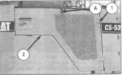
5. Attach Tool (A) to left side panel (2). Remove four bolts (1)_and remove the left side panel. The weight of the left side panel is 29 kg (64 lb). Note: During installation, shim the left side panel to 5 mm (0.197 inch).
6. Repeat Step 5 for the right side panel.
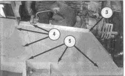
NOTE: The wheel assembly has been removed for photographic purposes only.
7. Remove bolts (4) from left side panel (3).
8. Loosen bolts (5) and remove left side panel (3).
9. Repeat steps 7 and 8 for the right side panel.
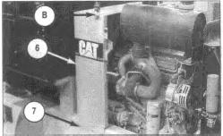
10. Attach Tooling (B) and a suitable hoist to support assembly (6). Loosen six bolts (7) and remove the support assembly from the machine. The weight of the support assembly is 26 kg (58 lb).
NOTE: Use steps 11 through 19 only if the machine is equipped with air conditioning.
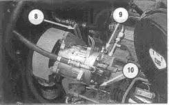
11. Disconnect two electrical connectors (9).
12. Remove the bolt from air conditioner compressor strap (8).
13. Remove bolt (10) and remove air conditioning unit. Move the air conditioning unit out of the way.
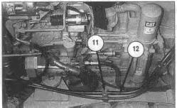
14. Remove three clamps (11) from two hose assemblies (12).
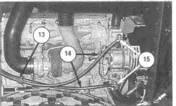
15. Turn shut off valves (15) off.
16. Disconnect two hose assemblies (14) from shut off valves (15). Plug hose assemblies immediately.
17. Remove clamp (13) from two hose assemblies (14).
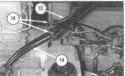
18. Remove clamps (16) from two hose assemblies (12) and (14).
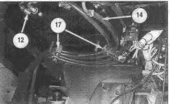
19. Remove clamps (17) from two hose assemblies (12) and (14).
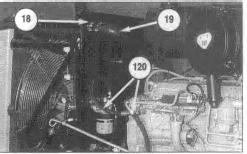
20. Disconnect air indicator tube (18) from the hydraulic oil tank frame.
21. Loosen the clamp and remove coolant hose (19) from the top of the hydraulic oil tank frame.
22. Disconnect fuel lines (20) from the engine. Cap and plug immediately.
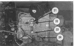
23. Disconnect three electrical connectors (21).
24. Disconnect three wires (22) from the fuel shutoff solenoid.
25. Remove the cable ties that fasten wiring harness (23) to the engine. Move the wiring harness out of the way.
26. Disconnect four hose assemblies (24) from the steering pump. Cap and plug immediately.
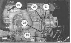
27. Disconnect wire (25) from the engine heater.
28. Disconnect electrical connector (26).
29. Disconnect two wires (27) from the alternator.
30. Remove the cable ties that fasten wiring harness (28) to the engine. Move the wiring harness out of the way.
31. Loosen the clamp, and remove coolant hose (29) from the engine.
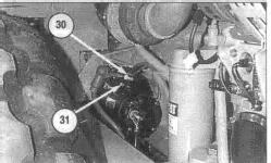
32. Remove five wires (30) from the starter.
33. Remove the nut and cover (31) from the starter.
34. Remove the remaining two wires from the starter.
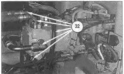
35. Disconnect hose assemblies (32) from the vibratory pump. Cap and plug immediately.
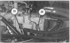
36. Disconnect electrical connection (33).
37. Disconnect hose (34) from the vibratory pump. Cap and plug immediately.
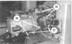
38. Disconnect two electrical connectors (35).
39. Disconnect hoses (36) from the propel pump. Cap and plug immediately.
40. Remove the cotter pin and pin that fastens control cable (37) to the propel pump. Loosen the jam nut and remove control cable (37) from the bracket. Move the control cable out of the way.
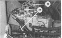
41. Remove the cable ties that fasten wiring harness (38) to the propel pump. Move the wiring harness out of the way.
42. Disconnect hoses (39) from the propel pump. Cap and plug immediately.
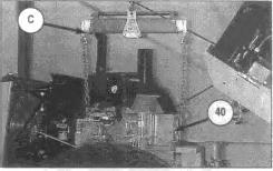
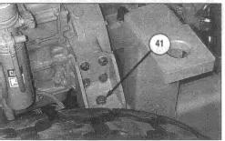
43. Attach Tooling (C) and a hoist to the engine (40) as shown. Remove four mounting bolts (41), and remove engine (40) and the pumps as a unit from the machine. The weight of the engine and pumps as a unit is approximately 726 kg (1600 lb).
NOTE: For the installation of the engine, reverse the removal steps.
NOTE: After the engine has been installed, fill the cooling system with coolant to the correct level. Fill the hydraulic oil system with hydraulic oil to the correct level. Refer to the Operation & Maintenance Manual, Form No. KEBU7506, for the correct procedures.
End By:
a. close engine enclosure or install hood
b. *lower operators platform
*This procedure is in the Machine Systems Disassembly & Assembly module, Form No. KENR3529.
Copyright 1993 - 2024 Caterpillar Inc. All Rights Reserved. Private Network For SIS Licensees.
Thu Jun 6 23:49:21 UTC+0530 2024
Product: VIBRATORY COMPACTOR
Model: CP-533D VIBRATORY COMPACTOR 6AZ
Configuration: CP-533D CS-533D Vibratory Compactor 6AZ00001-UP (MACHINE) POWERED BY 3116 Engine
Disassembly and Assembly 3116 ENGINE SUPPLEMENT FOR CS-531D, CP-533D AND CS-533D VIBR
Engine Enclosure (AGH1-UP, AET1-UP & AFC1-UP)
SMCS - 7263-010
Remove & Install Engine Enclosure

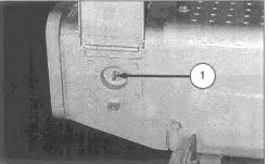
1. Move the engine enclosure raise/lower switch (1) up to raise the engine enclosure.
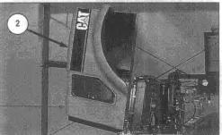
2. Raise engine enclosure (2) as shown.
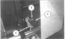
3. Disconnect two electrical wires (3) from the backup alarm (4).
4. Remove the cable ties that fasten wiring harness (5) to the backup alarm.
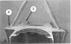
5. Attach lifting straps and Tool (A) to engine enclosure (2).
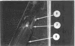
6. Remove bolt (6) and pin (7). Move actuator (8) out of the way.
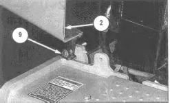
7. Remove bolt (9) from engine enclosure (2) and remove the engine enclosure. The weight of the engine enclosure is 136 kg (300 lb).
NOTE: To install the engine enclosure, reverse the removal steps.
Copyright 1993 - 2024 Caterpillar Inc.
Rights Reserved.
This is the sample of the manual click on the download link for complete manual
DOWNLOAD LINK
For some reason if link does not work download this pdf and then click