


Product: GENERATOR SET
Model: CG137-12 GENERATOR SET SC2
Configuration: CG137–12 Generator Set SC200001-UP
Operation and Maintenance Manual
CG137-12 Generator Set
s00242529
Foreword
Literature Information
This manual contains safety, operation instructions, lubrication and maintenance information. This manual should be stored in or near the engine area in a literature holder or literature storage area. Read, study and keep it with the literature and engine information.
English is the primary language for all Cat publications. The English used facilitates translation and consistency in electronic media delivery.
Some photographs or illustrations in this manual show details or attachments that may be different from your engine. Guards and covers may have been removed for illustrative purposes. Continuing improvement and advancement of product design may have caused changes to your engine which are not included in this manual. Whenever a question arises regarding your engine, or this manual, please consult with your Cat dealer for the latest available information.
Safety
This safety section lists basic safety precautions. In addition, this section identifies hazardous, warning situations. Read and understand the basic precautions listed in the safety section before operating or performing lubrication, maintenance and repair on this product.
Operation
Operating techniques outlined in this manual are basic. They assist with developing the skills and techniques required to operate the engine more efficiently and economically. Skill and techniques develop as the operator gains knowledge of the engine and its capabilities.
The operation section is a reference for operators. Photographs and illustrations guide the operator through procedures of inspecting, starting, operating and stopping the engine. This section also includes a discussion of electronic diagnostic information.
Maintenance
The maintenance section is a guide to engine care. The illustrated, step-by-step instructions are grouped by service hours and/or calendar time maintenance intervals. Items in the maintenance schedule are referenced to detailed instructions that follow.
Use service hours to determine intervals. Calendar intervals shown (daily, annually, etc) may be used instead of service meter intervals if they provide more convenient schedules and approximate the indicated service meter reading.
Recommended service should always be performed at the service hour interval. The actual operating environment of the engine also governs the maintenance schedule. Therefore, under extremely severe, dusty, wet or freezing cold operating conditions, more frequent lubrication and maintenance than is specified in the maintenance schedule may be necessary.
The maintenance schedule items are organized for a preventive maintenance management program. If the preventive maintenance program is followed, a periodic tune-up is not required. The implementation of a preventive maintenance management program should minimize operating costs through cost avoidances resulting from reductions in unscheduled downtime and failures.
Maintenance Intervals
Perform maintenance on items at multiples of the original requirement. Each level and/or individual items in each level should be shifted ahead or back depending upon your specific maintenance practices, operation and application. We recommend that the maintenance schedules be reproduced and displayed near the engine as a convenient reminder. We also recommend that a maintenance record be maintained as part of the engine's permanent record.
See the section in the Operation and Maintenance Manual, "Maintenance Records" for information regarding documents that are generally accepted as proof of maintenance or repair. Your authorized Cat dealer can assist you in adjusting your maintenance schedule to meet the needs of your operating environment.
California Proposition 65 Warning
Battery posts, terminals and related accessories contain lead and lead compounds. Wash hands after handling.
Overhaul
Major engine overhaul details are not covered in the Operation and Maintenance Manual except for the interval and the maintenance items in that interval. Major repairs are best left to trained personnel or an authorized Cat dealer. Your Cat dealer offers a variety of options regarding overhaul programs.
If you experience a major engine failure, there are also numerous after failure overhaul options available from your Cat dealer. Consult with your dealer for information regarding these options.
Copyright 1993 - 2024 Caterpillar Inc. All Rights Reserved. Private Network For SIS Licensees.
Thu Feb 8 22:19:29 UTC+0530 2024
This is the sample of the manual click on the download link for complete manual
DOWNLOAD LINK
For some reason if link does not work download this pdf and then click

Product: GENERATOR SET
Model: CG137-12 GENERATOR SET SC2
Configuration: CG137–12 Generator Set SC200001-UP
Operation and Maintenance Manual
CG137-12 Generator Set
Aftercooler Core - Clean/Test - Air-To-Air Aftercooler
SMCS - 1064-070; 1064-081
Note: Adjust the frequency of cleaning according to the effects of the operating environment.
Inspect the aftercooler for these items: damaged fins, corrosion, dirt, grease, insects, leaves, oil and other debris. Clean the aftercooler, if necessary.
For air-to-air aftercoolers, use the same methods that are used for cleaning radiators.
Personal injury can result from air pressure.
Personal injury can result without following proper procedure. When using pressure air, wear a protective face shield and protective clothing.
Maximum air pressure at the nozzle must be less than 205 kPa (30 psi) for cleaning purposes.
Pressurized air is the preferred method for removing loose debris. Direct the air in the opposite direction of the fan's air flow. Hold the nozzle approximately 6 mm (0.25 inch) away from the fins. The maximum air pressure for cleaning purposes must be below 205 kPa (30 psi) when the air nozzle is deadheaded. Slowly move the air nozzle in a direction that is parallel with the tubes. This will remove debris that is between the tubes.
Pressurized water may also be used for cleaning. The maximum water pressure for cleaning purposes must be less than 275 kPa (40 psi). Use pressurized water in order to soften mud. Clean the core from both sides.
Use a degreaser and steam for removal of oil and grease. Clean both sides of the core. Wash the core with detergent and hot water. Thoroughly rinse the core with clean water.
After cleaning, start the engine and accelerate the engine to high idle rpm. This will help in the removal of debris and drying of the core. Stop the engine. Use a light bulb behind the core in order to inspect the core for cleanliness. Repeat the cleaning, if necessary.
Inspect the fins for damage. Bent fins may be opened with a "comb".
Note: If parts of the aftercooler system are repaired or replaced, a leak test is highly recommended.
Inspect these items for good condition: welds, mounting brackets, air lines, connections, clamps and seals. Make repairs, if necessary.
For more detailed information on cleaning and inspection, see Special Publication, SEBD0518, "Know Your Cooling System".
Copyright 1993 - 2024 Caterpillar Inc. All Rights Reserved. Private Network For SIS Licensees. Thu Feb 8 22:21:28 UTC+0530 2024
Product: GENERATOR SET
Model: CG137-12 GENERATOR SET SC2
Configuration: CG137–12 Generator Set SC200001-UP
Operation and Maintenance Manual
CG137-12 Generator Set
Media Number -SEBU9313-00 Publication Date -01/04/2015
Updated -15/04/2015
i05952566
Air Inlet Filter - Inspect/Clean/Test - Engine Air Inlet Filter
SMCS - 1051-040; 1051-070; 1051-081
Monitor the connector contacts of the differential pressure switch for the air inlet filter. If the differential pressure rises above 15.2 mm (0.6 inch) of water. Replace the filter, if necessary.
Copyright 1993 - 2024 Caterpillar Inc. All Rights Reserved. Private Network For SIS Licensees. Thu Feb 8 22:21:47 UTC+0530 2024
Product: GENERATOR SET
Model: CG137-12 GENERATOR SET SC2
Configuration: CG137–12 Generator Set SC200001-UP
Operation and Maintenance Manual
CG137-12 Generator Set
-01/04/2015
Air Prelube Pump Lubricator Bowl - Clean
SMCS - 1319; 5507
-15/04/2015
Personal injury can result from removing hoses or fittings in a pressure system.
Failure to relieve pressure can cause personal injury.
Do not disconnect or remove hoses or fittings until all pressure in the system has been relieved.
NOTICE
Never allow the lubricator bowl to become empty. The prelube pump will be damaged by a lack of lubrication. Ensure that sufficient oil is in the lubricator bowl.
1. Shut off the air supply to the prelube system. Release the pressurized air from the system.

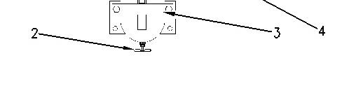
Illustration 1 g00716526
Prelube pump lubricator
(1) Filler plug
(2) Drain valve
(3) Clamp
(4) Retaining ring
2. Slowly remove filler plug (1) from the head of the lubricator in order to release the pressure from the lubricator bowl.
NOTICE
Care must be taken to ensure that fluids are contained during performance of inspection, maintenance, testing, adjusting and repair of the product. Be prepared to collect the fluid with suitable containers before opening any compartment or disassembling any component containing fluids.
Refer to Special Publication, NENG2500, "Caterpillar Tools and Shop Products Guide" for tools and supplies suitable to collect and contain fluids on Caterpillar products.
Dispose of all fluids according to local regulations and mandates.
3. Place a suitable container under the lubricator bowl and open drain valve (2) in order to drain any remaining oil from the bowl.
4. Loosen clamp (3). To remove the lubricator bowl, unscrew retaining ring (4).
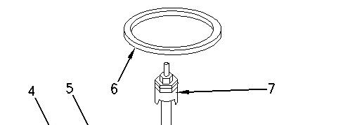


Illustration 2 g00716538
(4) Retaining ring
(5) Lubricator bowl
(6) Gasket
(7) Wick assembly
5. Remove retaining ring (4), lubricator bowl (5), and gasket (6), and wick assembly (7).
6. Clean the wick assembly and the bowl with nonflammable solvent.
Note: The height of the wick inside the lubricator bowl determines the amount of oil that is delivered by the lubricator. The height of the wick for the lubricator is set to the half position at the factory. The height of the wick must be adjusted when a reduction in the delivery of the oil mist is noticeable.
7. Use the following steps to adjust the rate of the oil mist, if necessary.
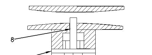
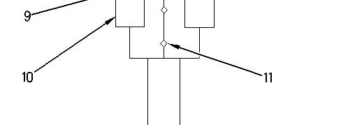

Illustration 3 g00716721
Wick assembly (7) in the venturi of the head of the lubricator (8) Wick (9) Locknut (10) Adjusting nut (11) Notch
a. Loosen locknut (9).
b. Adjust the height of wick (8) by turning adjusting nut (10).
To increase the oil mist, raise the wick. To decrease the oil mist, lower the wick.
Notch (11) is located on the adjusting nut. The height of the wick is visually indicated by the relative position of the notch to the bottom of locknut (9).
8. Install wick assembly (7) into lubricator bowl (5).
9. Inspect gasket (6) for good condition. If the gasket is damaged, obtain a new gasket for assembly. Install the gasket, lubricator bowl (7), and retaining ring (4). Tighten the retaining ring by hand.
10. Make sure that drain valve (2) is closed. Fill the lubricator bowl through the hole for filler plug (1) in the head of the lubricator.
11. Inspect the O-ring seal for filler plug (1). If the seal is damaged, obtain a new seal for assembly. Install the seal and the filler plug.
Copyright 1993 - 2024 Caterpillar Inc.
Rights Reserved.
Network For SIS Licensees. Thu Feb 8 22:22:10 UTC+0530 2024
Product: GENERATOR SET
Model: CG137-12 GENERATOR SET SC2
Configuration: CG137–12 Generator Set SC200001-UP
Operation and Maintenance Manual
CG137-12 Generator Set
Media Number -SEBU9313-00
-01/04/2015
Air Prelube Pump Lubricator Oil Level - Check
SMCS - 1319; 5507
NOTICE
Never allow the lubricator bowl to become empty. The air starting motor will be damaged by a lack of lubrication. Ensure that sufficient oil is in the lubricator bowl.
-15/04/2015
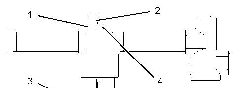

Illustration 1 g01333366
1. Observe the oil level in sight gauge (3). If the oil level is less than 1/2, add oil to the lubricator bowl.
Personal injury can result from removing hoses or fittings in a pressure system.
Failure to relieve pressure can cause personal injury.
Do not disconnect or remove hoses or fittings until all pressure in the system has been relieved.
2. Ensure that the air supply to the lubricator is OFF. Slowly loosen filler plug (4) in order to release pressure from the lubricator bowl.
3. Remove filler plug (4). Pour oil into the lubricator bowl. Use nondetergent SAE 10W oil for temperatures that are greater than 0 °C (32 °F). Use air tool oil for temperatures that are below 0 °C (32 °F).
4. Install filler plug (4).
Adjust the Lubricator
Note: Adjust the lubricator with a constant rate of air flow. After the adjustment, the lubricator will release oil in proportion to variations of the air flow.
1. Ensure that the fuel supply to the engine is OFF.
NOTICE
Do not crank the engine continuously for more than 30 seconds. Allow the starting motor to cool for two minutes before cranking the engine again.
2. Operate the air starting motor. Observe the drops of oil that are released in dome (1).
Note: Some lubricators have an adjustment screw rather than a knob.
3. If necessary, adjust the lubricator in order to release from one to three drops of oil per second. To increase the rate, turn knob (2) counterclockwise. To decrease the rate, turn the knob clockwise.
1993 - 2024 Caterpillar Inc.
Thu Feb 8 22:22:54 UTC+0530 2024
Product: GENERATOR SET
Model: CG137-12 GENERATOR SET SC2
Configuration: CG137–12 Generator Set SC200001-UP
Operation and Maintenance Manual
CG137-12 Generator Set
Air Tank Moisture and Sediment - Drain
SMCS - 1466-543-M&S
Moisture and sediment in the air starting system can cause the following conditions:
• Freezing
• Corrosion of internal parts
• Malfunction of the air starting system
When opening the drain valve, wear protective gloves, a protective face shield, protective clothing, and protective shoes. Pressurized air could cause debris to be blown and result in personal injury.
NOTICE
Care must be taken to ensure that fluids are contained during performance of inspection, maintenance, testing, adjusting, and repair of the product. Be prepared to collect the fluid with suitable containers before opening any compartment or disassembling any component containing fluids.
Refer to Special Publication, NENG2500, "Cat Dealer Service Tool Catalog" or refer to Special Publication, PECJ0003, "Cat Shop Supplies and Tools Catalog" for tools and supplies suitable to collect and contain fluids on Cat products.
Dispose of all fluids according to local regulations and mandates.
1. Open the drain valve that is on the bottom of the air tank. Allow the moisture and sediment to drain.
2. Close the drain valve.
Copyright 1993 - 2024 Caterpillar Inc. All Rights Reserved. Private Network For SIS Licensees.
Thu Feb 8 22:23:03 UTC+0530 2024
Product: GENERATOR SET
Model: CG137-12 GENERATOR SET SC2
Configuration: CG137–12 Generator Set SC200001-UP
Operation and Maintenance Manual
CG137-12 Generator Set
Media Number -SEBU9313-00
Alternator - Inspect
SMCS - 1405-040
Inspect the alternator for the following conditions:
• Proper connections
• Clean ports for cooling airflow
• Proper charging of the battery
-01/04/2015
-15/04/2015
i04342909
Observe the ammeter during engine operation in order to ensure proper battery performance and/or proper performance of the electrical system.
Make repairs, if necessary. See the Service Manual for service procedures. Consult your Cat dealer for assistance.
Copyright 1993 - 2024 Caterpillar Inc. All Rights Reserved. Private Network For SIS Licensees. Thu Feb 8 22:23:11 UTC+0530 2024
Product: GENERATOR SET
Model: CG137-12 GENERATOR SET SC2
Configuration: CG137–12 Generator Set SC200001-UP
Operation and Maintenance Manual
CG137-12 Generator Set
Media Number -SEBU9313-00 Publication Date -01/04/2015
Automatic Start/Stop - Inspect - Generator Set
SMCS - 4462
-15/04/2015
i01039675
The generator set must be ready to operate under a load at any time. After performing maintenance on the generator set, inspect the position of the control switches. Ensure the following conditions:
• The starting system is enabled.
• The control switches are in the correct position for automatic starting.
• The switchgear and the automatic transfer switches that are associated with the generator are enabled.
For more information, see the Operation and Maintenance Manual for the generator and the control panel.
Copyright 1993 - 2024 Caterpillar Inc. All Rights Reserved. Private Network For SIS Licensees.
Thu Feb 8 22:23:19 UTC+0530 2024
Product: GENERATOR SET
Model: CG137-12 GENERATOR SET SC2
Configuration: CG137–12 Generator Set SC200001-UP
Operation and Maintenance Manual
CG137-12 Generator Set
Media Number -SEBU9313-00
Publication Date -01/04/2015 Date Updated -15/04/2015
Battery - Recycle
SMCS - 1401-005; 1401-510; 1401-535; 1401-561; 1401
Always recycle a battery. Never discard a battery.
Always return used batteries to one of the following locations:
• A battery supplier
• An authorized battery collection facility
• Recycling facility
Copyright 1993 - 2024 Caterpillar Inc. All Rights Reserved. Private Network For SIS Licensees. Thu Feb 8 22:23:31 UTC+0530 2024
Product: GENERATOR SET
Model: CG137-12 GENERATOR SET SC2
Configuration: CG137–12 Generator Set SC200001-UP
Operation and Maintenance Manual
CG137-12 Generator Set
Battery - Replace
SMCS - 1401-510
Batteries give off combustible gases which can explode. A spark can cause the combustible gases to ignite. This can result in severe personal injury or death.
Ensure proper ventilation for batteries that are in an enclosure. Follow the proper procedures in order to help prevent electrical arcs and/or sparks near batteries. Do not smoke when batteries are serviced.
1. Turn the key start switch to the OFF position. Remove the key and all electrical loads.
2. Turn OFF the battery charger. Disconnect the charger.
3. The NEGATIVE "-" cable connects the NEGATIVE "-" battery terminal to the ground plane. Disconnect the cable from the NEGATIVE "-" battery terminal.
4. The POSITIVE "+" cable connects the POSITIVE "+" battery terminal to the starting motor. Disconnect the cable from the POSITIVE "+" battery terminal.
Note: Always recycle a battery. Never discard a battery. Return used batteries to an appropriate recycling facility.
5. Remove the used battery.
6. Install the new battery.
Note: Before connecting the cables, ensure that the key start switch is OFF.
7. Connect the cable from the starting motor to the POSITIVE "+" battery terminal.
8. Connect the cable from the ground plane to the NEGATIVE "-" battery terminal.
Copyright 1993 - 2024 Caterpillar Inc. All Rights Reserved. Private Network For SIS Licensees.
Thu Feb 8 22:23:40 UTC+0530 2024
Product: GENERATOR SET
Model: CG137-12 GENERATOR SET SC2
Configuration: CG137–12 Generator Set SC200001-UP
Operation and Maintenance Manual
CG137-12 Generator Set
Battery Charger - Check
SMCS - 1401-535
Checking Before Start-Up
Check the battery charger for proper operation. If the batteries are properly charged, the needle of the ammeter will register near "0" (zero).
The battery charger must not produce excessive current during start-up. Alternatively, the charger must be automatically disconnected for start-up. If the engine has an alternator, the charger must be automatically disconnected during start-up and during engine operation.
Charging the Battery
Never disconnect any charging unit circuit or battery circuit cable from the battery when the charging unit is operated. A spark can cause an explosion from the flammable vapor mixture of hydrogen and oxygen that is released from the electrolyte through the battery outlets. Injury to personnel can be the result.
Perform the following procedure to charge the battery:
1. Ensure that the charger is turned OFF.
2. Adjust the voltage of the charger in order to match the voltage of the battery.
3. Connect the POSITIVE "+" lead of the charger to the POSITIVE "+" battery terminal. Connect the NEGATIVE "-" lead of the charger to the NEGATIVE "-" battery terminal.
4. Turn ON the battery charger.
Overcharging of Batteries
Overcharging reduces the service life of batteries. Use a battery charger that will not overcharge the battery. DO NOT charge the battery if the meter of the battery charger is in the RED zone.
Overcharging is indicated by the following symptoms:
• The battery is warm to the touch.
• A strong odor of acid is present.
• The battery emits smoke or a dense vapor (gas).
Perform one of the following procedures if the battery shows symptoms of overcharging:
• Reduce the rate of charging by a significant amount. Complete the charging at the reduced rate.
• Turn OFF the charger.
Table 1 describes the effects of overcharging on different types of batteries.
Table 1
Effects of Overcharging Batteries
Type of Battery Effect
Cat General Service Batteries
Cat Premium High Output Batteries
Cat Maintenance Free Batteries
All of the battery cells have a low level of electrolyte.
When the plates of the battery are inspected through the filler holes, the plates may appear to be warped. This is caused by an excessive temperature.
The battery may not pass a load test.
The battery may not accept a charging current. The battery may not pass a load test.
Checking After Stopping
Ensure that the battery charger is connected properly. Observe the meter of the charger. Record the amperage.
Copyright 1993 - 2024 Caterpillar Inc. All Rights Reserved. Private Network For SIS Licensees. Thu Feb 8 22:23:49 UTC+0530 2024
Product: GENERATOR SET
Model: CG137-12 GENERATOR SET SC2
Configuration: CG137–12 Generator Set SC200001-UP
Operation and Maintenance Manual
CG137-12 Generator Set
Battery Electrolyte Level - Check
SMCS - 1401-535-FLV
When the engine has not run for long or short periods of time, the batteries may not fully recharge. Ensure a full charge to help prevent the battery from freezing.
In warmer climates, check the electrolyte level more frequently.
Ensure that the electrolyte level is 13 mm (0.5 inch) above the top of the separators.
All lead-acid batteries contain sulfuric acid which can burn the skin and clothing. Always wear a face shield and protective clothing when working on or near batteries.
1. Remove the filler caps. Maintain the electrolyte level to the "FULL" mark on the battery.
If the addition of water is necessary, use distilled water. If distilled water is not available, use clean water that is low in minerals. Do not use artificially softened water.
2. Check the condition of the electrolyte with the 245-5829 Coolant Battery Tester Refractometer.
3. Keep the batteries clean.
Clean the battery case with one of the following cleaning solutions:
A mixture of 0.1 kg (0.2 lb) of baking soda and 1 L (1 qt) of clean water
A mixture of 0.1 L (0.11 qt) of ammonia and 1 L (1 qt) of clean water
Thoroughly rinse the battery case with clean water.
Use the 1U-9921 Battery Service Tool to clean the battery terminals. Use a wire brush to clean the cable clamps. Clean the items until the surfaces are bright or shiny. DO NOT remove material excessively. Excessive removal of material can cause the clamps to fit improperly. Coat the clamps and the terminals with 5N-5561 Silicone Lubricant, petroleum jelly or MPGM.
Copyright 1993 - 2024 Caterpillar Inc. All Rights Reserved. Private Network For SIS Licensees.
Thu Feb 8 22:23:59 UTC+0530 2024
This is the sample of the manual click on the download link for complete manual
DOWNLOAD LINK
For some reason if link does not work download this pdf and then click