


Note: Use Bookmarks panel to navigate
This is the sample of the manual click on the download link for complete manual
DOWNLOAD LINK
For some reason if link does not work download this pdf and then click

Product: GENERATOR SET
Model: CG137-12 GENERATOR SET SC2
Configuration: CG137–12 Generator Set SC200001-UP
Disassembly and Assembly
CG137-08 and CG137-12 Engines
Aftercooler - Remove and Install - G3408B
SMCS - 1063-010
S/N - FPL1-UP
S/N - SC21-UP
S/N - WWF1-UP
Removal Procedure
Table 1
i05183090
(1) For Use in EAME
Start By:
a. Remove the carburetor.
1. Refer to Operation and Maintenance Manual, "Coolant - Change" for the proper draining and filling procedures.
1
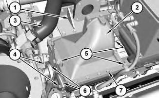
2. Remove bracket (1). If necessary place tube assembly (3) to the side.
3. Remove clips (5).
4. Remove bolts (4). Remove adapters (6) and O-ring seals.
5. Remove bolts (7) and cover (2). Inspect and replace gasket if necessary.
2
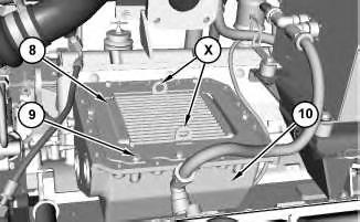
6. Remove bolts (9) and attach a suitable lifting device to Locations (X) on aftercooler (8). The weight of aftercooler (8) is approximately 30 kg (65 lb).
7. Remove aftercooler (8). If necessary, remove housing (10).
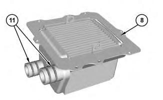
Illustration 3
8. Remove O-ring seals (11) from aftercooler (8).
Installation Procedure
1. Install aftercooler (8) in the reverse order of removal.
a. Apply Tooling (A) to O-ring seals (11) and the bores.
Copyright 1993 - 2024 Caterpillar Inc. All Rights Reserved. Private Network For SIS Licensees. Thu Feb 8 23:04:06 UTC+0530 2024
Product: GENERATOR SET
Model: CG137-12 GENERATOR SET SC2
Configuration: CG137–12 Generator Set SC200001-UP
Disassembly and Assembly
CG137-08 and CG137-12 Engines
Aftercooler - Remove and Install - G3412B
SMCS - 1063-010
S/N - FYR1-UP
S/N - SC21-UP
S/N - WRX1-UP
Removal Procedure
Table 1
Required Tools
(1) For Use in EAME
1. Refer to Operation and Maintenance Manual, "Coolant - Change" for the proper draining and filling procedures.
1
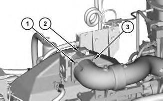
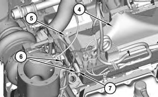
2. Remove bolts (1) and remove tube assembly (3). Remove throttle (2).
2
3. Remove bolts (6). Remove adapters (7) and remove the O-ring seals.
4. Remove bolts (5).
Note: Position any clips, brackets, and harness assemblies out of the way.
5. Use two people to remove cover (4). The weight of cover (4) is approximately 25 kg (55 lb). Discard the gasket and replace upon installation.
3
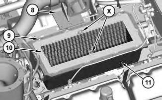
6. If necessary, remove bracket (8).
7. Remove bolts (9) and attach a suitable lifting device to Locations (X) on aftercooler (10). The weight of aftercooler (10) is approximately 59 kg (130 lb).
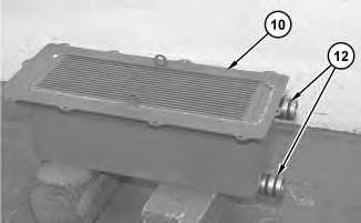
8. Remove aftercooler (10). If necessary, remove housing (11). The weight of housing (11) is approximately 40 kg (88 lb).
4 g02735920
9. Remove O-ring seals (12) from aftercooler (10).
Installation Procedure
1. Install aftercooler (10) in the reverse order of removal.
a. Apply Tooling (A) to O-ring seals (12) and the bores.
Copyright 1993 - 2024 Caterpillar Inc. All Rights Reserved. Private Network For SIS Licensees. Thu Feb 8 23:04:25 UTC+0530 2024
Product: GENERATOR SET
Model: CG137-12 GENERATOR SET SC2
Configuration: CG137–12 Generator Set SC200001-UP
Disassembly and Assembly
CG137-08 and CG137-12 Engines
Media
Air Cleaner Housing - Remove and Install
SMCS - 1051-010
Removal Procedure
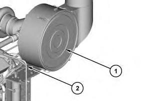
Illustration 1
g02653124
1. Remove cover (1) and the air filter element.
2. Disconnect tube assembly (2).
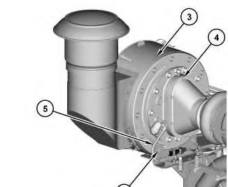
3. Disconnect hose assembly (5). Remove bolts (4).
4. Use two people to support air cleaner housing (3). The weight of air cleaner housing (3) is approximately 36 kg (79 lb).
5. Remove bolts (6) and remove air cleaner housing (3).
Installation Procedure
1. Install air cleaner housing (3) in the reverse order of removal.
Copyright 1993 - 2024 Caterpillar Inc. All Rights Reserved. Private Network For SIS Licensees. Thu Feb 8 23:04:45 UTC+0530 2024
Product: GENERATOR SET
Model: CG137-12 GENERATOR SET SC2
Configuration: CG137–12 Generator Set SC200001-UP
Disassembly and Assembly
CG137-08 and CG137-12 Engines
Air Starting Motor - Remove and Install - Alternate Air
Starting Motor - TDI
SMCS - 1451-010
S/N - FYR1-UP
S/N - SC21-UP
S/N - WRX1-UP
S/N - WWF1-UP
Removal Procedure
Accidental engine starting can cause injury or death to personnel working on the equipment.
To avoid accidental engine starting, disconnect the battery cable from the disconnected battery cable end in order to prevent contact with other metal surfaces which could activate the engine electrical system.
Place a Do Not Operate tag at the Start/Stop switch location to inform personnel that the equipment is being worked on.
1. 367-6268 Pressure Regulator is not shown. If equipped, remove the pressure regulator first, and procedure with the procedure below.
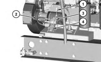
Illustration 1
2. Disconnect harness assembly (1).
3. Remove hose assembly (2).
4. Remove solenoid valve assembly (3) and remove relay valve (4).
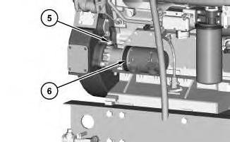
Illustration 2
g02712081
5. Remove bolts (5). Remove air starting motor (6) and discard the gasket. Install a new gasket upon installation.
Installation Procedure
1. Install air starting motor (6) in the reverse order of removal. Copyright 1993 - 2024 Caterpillar Inc.
Product: GENERATOR SET
Model: CG137-12 GENERATOR SET SC2
Configuration: CG137–12 Generator Set SC200001-UP
Disassembly and Assembly
CG137-08 and CG137-12 Engines
Air Starting Motor - Remove and Install
SMCS - 1451-010
Removal Procedure
Accidental engine starting can cause injury or death to personnel working on the equipment.
To avoid accidental engine starting, disconnect the battery cable from the disconnected battery cable end in order to prevent contact with other metal surfaces which could activate the engine electrical system.
Place a Do Not Operate tag at the Start/Stop switch location to inform personnel that the equipment is being worked on.
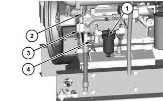
Illustration 1
g02712053
1. Drain the fuel from air motor lubricator assembly (1).
2. Disconnect harness assembly (2). Remove solenoid valve (3).
3. Remove hose assemblies (4) and the elbow adapters
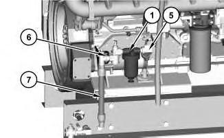
Illustration 2
g02712064
4. Disconnect reducing valve (5) and remove hose assembly (7).
5. Remove air motor lubricator assembly (1).
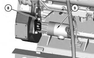
Illustration 3
g02712069
6. Remove bolts (8). Remove air starting motor (9), the bracket, and the gasket. Discard the gasket, and replace with a new gasket for installation.
Installation Procedure
1. Install air starting motor (9) in the reverse order of removal.
a. After installation, fill air motor lubricator assembly (1) with diesel fuel.
Thu Feb 8 22:58:25 UTC+0530 2024
Product: GENERATOR SET
Model: CG137-12 GENERATOR SET SC2
Configuration: CG137–12 Generator Set SC200001-UP
Disassembly and Assembly
CG137-08 and CG137-12 Engines Media
-UENR0103-04
Auxiliary Water Pump - Assemble
SMCS - 1361-016
Assembly Procedure Table 1
Required Tools
A 1P-1857 Snap Ring Pliers 1
C 1P-1855 Snap Ring Pliers 1
D 9S-9152 Bearing Puller 1
NOTICE
Keep all parts clean from contaminants.
Contaminants may cause rapid wear and shortened component life.
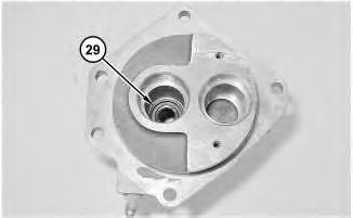
Illustration 1
1. Install lip seal (29) in the pump housing.
2. Install lip seal (29) with the lip away from the impeller.
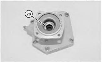
Illustration 2
3. Install slinger (28) in the pump housing.
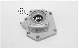
Illustration 3
4. Install ceramic ring (27) in the pump housing.
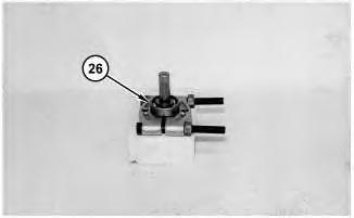
Illustration 4
5. Put the intermediate shaft in Tooling (D) .
g01425759
6. Raise the temperature of bearing (26) to a temperature of 135 °C (275 °F) and install bearing (26) on the shaft.
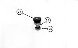
Illustration 5
g01425764
7. Install spacer (24) . Raise the temperature of bearing (25) to a temperature of 135 °C (275 ° F) and install bearing (25) on the shaft.
8. Raise the temperature of gear (23) to a temperature of 135 °C (275 °F) and install gear (23) on the shaft.
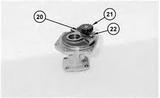
Illustration 6
9. Install shaft assembly (21) into the pump housing. Position lock (20) and install bolts (22) . Tighten bolts (22) to a torque of 12 ± 3 N·m (9 ± 2 lb ft).
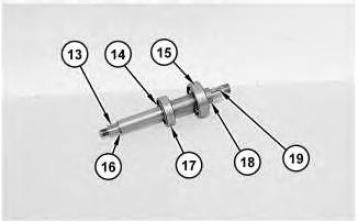
Illustration 7
g01425766
10. Install retainer ring (14) on the shaft with Tool (C) .
11. Install bearing (17) . Raise the temperature of bearing (15) to a temperature of 135 °C (275 ° F). Install bearing (15) . Install spacer (18) , shims (16) , and keys (13) and (19) on the shaft.
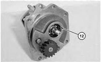
Illustration 8
g01425875
12. Install the shaft assembly in the pump housing.
13. Install retainer ring (12) with Tool (A) .
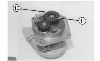
Illustration 9
g01425770
14. Install gear (10) , the washer, and nut (11) . Tighten nut (11) to a torque of 60 ± 7 N·m (44 ± 5 lb ft).
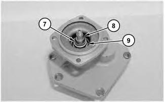
Illustration 10
g01425772
NOTICE
Clean water only is permitted for use as a lubricant for assistance at installation. Do not damage or put hands on the wear surface of the carbon ring or the ceramic ring. Install the ceramic ring with the smoothest face of the ring toward the carbon seal assembly.
15. Position the lower portion of seal assembly (9) in hot water. Install seal assembly (9) on the shaft. Install shims (7) and key (8) .
11
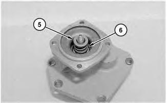
Personal injury can result from parts and/or covers under spring pressure.
Spring force will be released when covers are removed. Be prepared to hold spring loaded covers as the bolts are loosened.
16. Install spring (6) and retainer (5) .
12
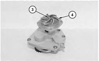
17. Restrain gears with a soft jawed vise. Install impeller (4) and locknut (3) . Tighten locknut (3) to a torque of 29.5 ± 2.5 N·m (21.80 ± 1.80 lb ft).
Note: Do not hold impeller (4) while tightening locknut (3) .
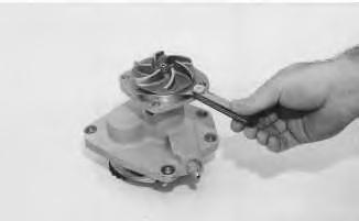
Illustration 13
g00792363
18. Check the clearance of the impeller. Shims should be added just until the impeller is clear of the housing.
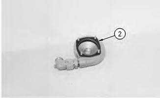
Illustration 14
19. Install gasket (2) on the impeller housing.
g00792161
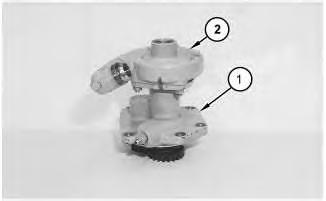
Illustration 15 g01425777
20. Install impeller housing (2) on pump housing (1) . Ensure that the identification marks are in alignment.
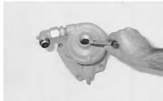
Illustration 16
21. Check the impeller clearance again.
g00792366
End By: Install the auxiliary water pump. Refer to Disassembly and Assembly, "Auxiliary Water Pump - Install".
Copyright 1993 - 2024 Caterpillar Inc. All Rights Reserved. Private Network For SIS Licensees. Thu Feb 8 23:11:58 UTC+0530 2024
Product: GENERATOR SET
Model: CG137-12 GENERATOR SET SC2
Configuration: CG137–12 Generator Set SC200001-UP
Disassembly and Assembly
CG137-08 and CG137-12 Engines
Auxiliary Water Pump - Disassemble
SMCS - 1361-015
Disassembly Procedure Table 1
Required Tools
Tool Part Number Part Description Qty
A 1P-1857 Snap Ring Pliers 1
B 1P-0510 Driver Group 1
C 1P-1855 Snap Ring Pliers 1
D 9S-9152 Bearing Puller 1
Start By:
a. Remove the auxiliary water pump. Refer to Disassembly and Assembly, "Auxiliary Water Pump - Remove".
NOTICE
Care must be taken to ensure that fluids are contained during performance of inspection, maintenance, testing, adjusting, and repair of the product. Be prepared to collect the fluid with suitable containers before opening any compartment or disassembling any component containing fluids.
Refer to Special Publication, NENG2500, "Dealer Service Tool Catalog" for tools and supplies suitable to collect and contain fluids on Cat products.
Dispose of all fluids according to local regulations and mandates.
NOTICE
Keep all parts clean from contaminants.
Contaminants may cause rapid wear and shortened component life.
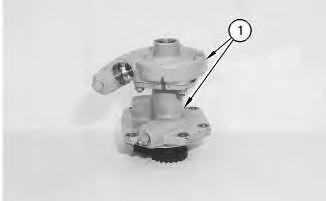
Illustration 1
g00792160
Illustration 2
g00792161
1. Put identification marks on the pump housings (1) and separate the housings. Remove gasket (2) between the housings.
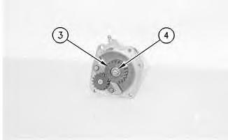
Illustration 3 g00792163
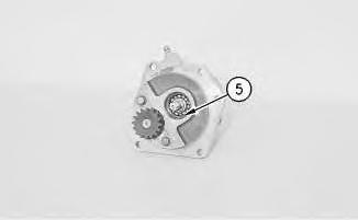
Illustration 4 g00792169
2. Remove locknut (4), the washer, and gear (3).
3. Remove retainer ring (5) with Tooling (A).
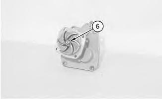
Illustration 5
g00792172
This is the sample of the manual click on the download link for complete manual
DOWNLOAD LINK
For some reason if link does not work download this pdf and then click