DOWNLOAD LINK
For some reason if link does not work download this pdf and then click
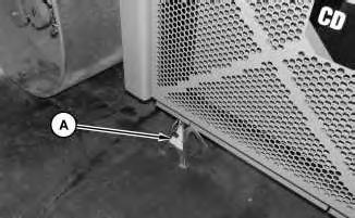
1. Raise the machine and install Tooling (A) to both sides of the machine.
Illustration 2
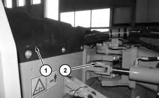
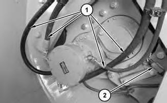
2. Remove panel (1) and pin (2).
g03006976
Illustration 3
g03007016
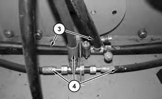
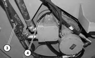
3. Disconnect hoses (3) and hose assemblies (4).
Illustration 4
g03007037
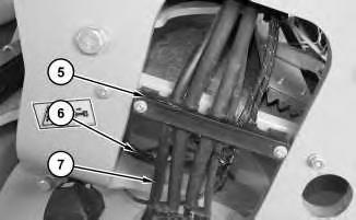
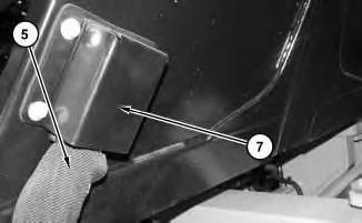
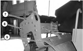
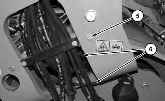
4. Remove bracket assembly (5). Disconnect harness assemblies (6) and hose assemblies (7). Repeat for opposite side.
Illustration 5
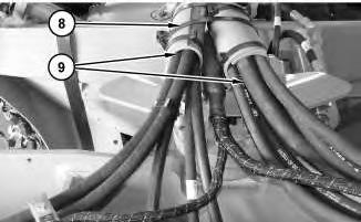
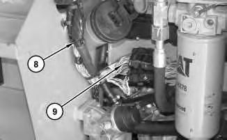
5. Cut cable straps (8). Reposition hoses (9).
Illustration 6
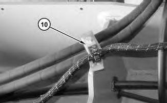
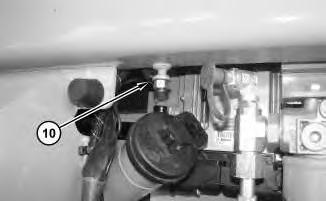
6. Disconnect clamp assembly (10). Repeat for other side
Illustration 7
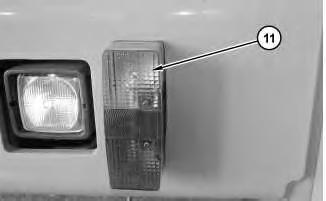
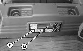
7. Remove cover (11). Repeat for other side.
g03007079
g03007117
g03007157
Illustration 8
g03007179
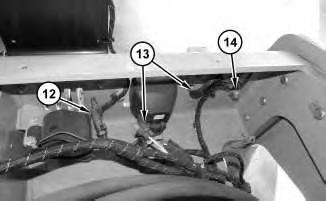
8. Disconnect harness assemblies (12), and (13). Disconnect ground strap (14)
Illustration 9
g03006522
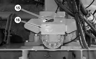
9. Remove plate (16). Disconnect harness assembly (15).
Illustration 10
g03007216
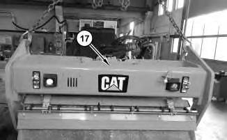
10. Use suitable lifting device to remove front roller assembly (17). The weight of the front roller assembly (17) is approximately 2948 kg (6500 lb).
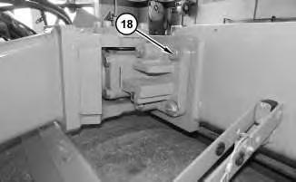
11. Remove bolts (18). Repeat for opposite side.
Installation Procedure
1. Install front roller assembly (17) in reverse order of the removal. Tighten the hitch bolts (18) to a torque of 600 ± 50 N·m (443 ± 37 lb ft). Copyright 1993 - 2025 Caterpillar Inc. All Rights Reserved.
Network For SIS Licensees. Mon Feb 24 23:16:17 UTC+0700 2025
Product: COMPACTOR
Model: CD10 COMPACTOR J6B
Configuration: CD10 Asphalt Compactor J6B00001-UP (MACHINE) POWERED BY C3.4B Engine
Disassembly and Assembly
CD8 and CD10 Vibratory Asphalt Compactors Machine Systems
Media Number -M0079205-03
Publication Date -01/09/2015
Date Updated -14/08/2019
i07115321
Blower Motor (Air Conditioner, Heater) - Remove and Install
SMCS - 7304-010-FM; 7304-010-BW; 7309-010-BW; 7309-010-FM; 7320-010-BW; 7320-010FM
Removal Procedure
1
1. Disconnect harness assemblies (3).
2. Disconnect cable assembly (4).
3. Remove bolts (1) and cover (2).
Illustration
g02996457
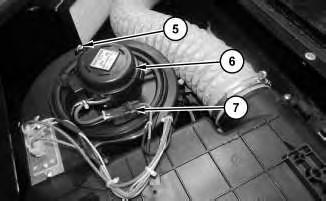
4. Remove bolt (5).
5. Disconnect harness assembly (7).
6. Remove blower motor (air conditioner, heater) (6).
Installation
Procedure
1. Install blower motor (air conditioner, heater) (6) in the reverse order of removal.
1993 - 2025 Caterpillar Inc.
Product: COMPACTOR
Model: CD10 COMPACTOR J6B
Configuration: CD10 Asphalt Compactor J6B00001-UP (MACHINE) POWERED BY C3.4B Engine
Disassembly and Assembly
CD8 and CD10 Vibratory Asphalt Compactors Machine Systems Media Number -M0079205-03
Cab - Remove and Install
SMCS - 7301-010; 7325-010
Removal Procedure Table 1
Required Tools
Tool Part Number Part Description Qty A 138-7575 Link Brackets 4
Start By:
a. Release system pressure.
b. Engage steering lock valve.
Personal injury can result from contact with refrigerant.
This system is under pressure at all times, even if the engine is not running. Heat should never be applied to a charged system.
Contact with refrigerant can cause frost bite. Keep face and hands away to help prevent injury.
Protective goggles must always be worn when refrigerant lines are opened, even if the gauges indicate the system is empty of refrigerant.
i04839711
Always use caution when a fitting is removed. Slowly loosen the fitting. If the system is still under pressure, evacuate the system recovering the refrigerant before removing the fitting.
Personal injury or death can result from inhaling refrigerant through a lit cigarette.
Inhaling air conditioner refrigerant gas through a lit cigarette or other smoking method or inhaling fumes released from a flame contacting air conditioner refrigerant gas, can cause bodily harm or death.
Do not smoke when servicing air conditioners or wherever refrigerant gas may be present.
Before any checks of the air conditioning and heating system are made, move the machine to a smooth horizontal surface. Lower all implements to the ground. Make sure the transmission is in neutral or park and that the parking brake is engaged. Keep all other personnel away from the machine or where they can be seen.
1. Recover the air conditioner refrigerant from the air conditioner system. Refer to Service Manual, SENR5664, "Air Conditioning and Heating Systems with R-134a Refrigerant" for the correct procedure. Refer to Special Publication, NEDG2500, "Air Conditioning Tools" for the correct tools.
2. Refer to Operation and Maintenance Manual, "Cooling System Coolant (ELC) - Change" for the correct draining and filling procedures.
1
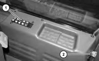
3. Remove switch board (1). Disconnect harness assemblies (2).
Illustration
g02970596
2
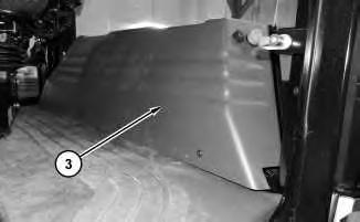
4. Remove panel (3).
3
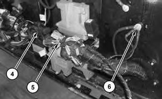
5. Remove cable straps (4). Disconnect harness assembly (6) and harness assembly (5).
4
6. Remove panel (7). Reposition harness assembly (5).
Illustration
g02970637
Illustration
g02970639
Illustration
g02970656
5
7. Remove cable straps (8). Disconnect harness assemblies (9).
6
8. Disconnect harness assembly (10).
7
9. Remove panel (11) and door (12).
Illustration
g02970677
Illustration
g02970696
Illustration
g02970697
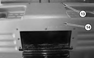
10. Remove bolts (13). Reposition panel (14).
9
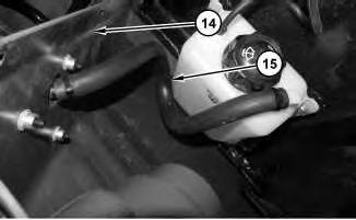
11. Disconnect hose (15). Remove panel (14).
10
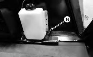
12. Disconnect tube (16).
Illustration 8
g02970699
Illustration
g02972124
Illustration
g02970718
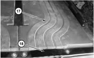
13. Remove plates (18). Reposition floor mats (17).
12
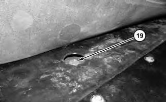
14. Reposition floor mats (19).
13
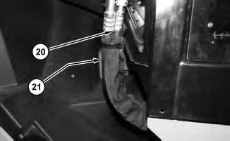
Note: Use a backer wrench on hose couplings to prevent seal damage.
15. Disconnect hose assemblies (20) and hoses (21).
Illustration 11
g02970737
Illustration
g02970816
Illustration
g02970839
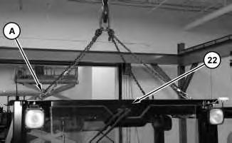
16. Attach Tooling (A) and a suitable lifting device to cab (22). The weight of cab (22) is approximately 1134 kg (2500 lb). Remove cab (22).
Installation Procedure
1. Install cab (23) in the reverse order of removal.
Copyright 1993 - 2025 Caterpillar Inc. All Rights Reserved. Private Network For SIS Licensees. Mon Feb 24 23:24:34 UTC+0700 2025
Product: COMPACTOR
Model: CD10 COMPACTOR J6B
Configuration: CD10 Asphalt Compactor J6B00001-UP (MACHINE) POWERED BY C3.4B Engine
Disassembly and Assembly
CD8 and CD10 Vibratory Asphalt Compactors Machine Systems
Media Number -M0079205-03 Publication Date -01/09/2015
Control Valve (Main) - Remove and Install
SMCS - 5051-010-MV
Removal Procedure
Start By:
a. Release system pressure.
-14/08/2019
1. Drain the hydraulic oil from the hydraulic tank into a suitable container for storage or disposal. Refer to Operation and Maintenance Manualfor the correct procedure for the correct draining and filling procedures.
Illustration 1
2. Remove deflector (1).
g02949878
i04823550
2
3. Remove bolts (2) and pipe assembly (3).
g02950056
Illustration 3
g02950099
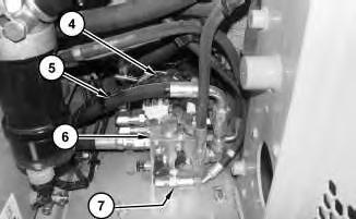
4. Disconnect harness assemblies (4) and hose assemblies (5).
5. Remove bolts (7) and control valve (main) (6).
Installation Procedure
1. Install control valve (main) (6) in the reverse order of removal.
Copyright 1993 - 2025 Caterpillar Inc. All Rights Reserved. Private Network For SIS Licensees. Mon Feb 24 23:16:33 UTC+0700 2025
Illustration
Product: COMPACTOR
Model: CD10 COMPACTOR J6B
Configuration: CD10 Asphalt Compactor J6B00001-UP (MACHINE) POWERED BY C3.4B Engine
Disassembly and Assembly
CD8 and CD10 Vibratory Asphalt Compactors Machine Systems
Media Number -M0079205-03 Publication Date -01/09/2015 Date Updated -14/08/2019
Control Valve (Steering, Offset) - Remove and Install
SMCS - 4307-010; 4343-010-VL; 5051-010
Removal Procedure
Start By:
a. Release system pressure.
Personal injury can result from hydraulic oil pressure and hot oil.
Hydraulic oil pressure can remain in the hydraulic system after the engine has been stopped. Serious injury can be caused if this pressure is not released before any service is done on the hydraulic system.
Make sure all of the work tools have been lowered to the ground, and the oil is cool before removing any components or lines. Remove the oil filler cap only when the engine is stopped, and the filler cap is cool enough to touch with your bare hand.
1. Drain the hydraulic oil from the hydraulic tank into a suitable container for storage or disposal. Refer to Operation and Maintenance Manualfor the correct procedure for the correct draining and filling procedures.
i04846378
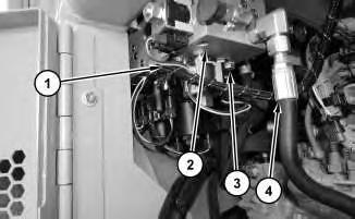
2. Disconnect harness assembly (1).
3. Disconnect hose assemblies (4) .
4. Remove bolts (3) and control valve (2).
Installation Procedure
1. Install control valve (2) in the reverse order of removal.
1993 - 2025 Caterpillar Inc.
Product: COMPACTOR
Model: CD10 COMPACTOR J6B
Configuration: CD10 Asphalt Compactor J6B00001-UP (MACHINE) POWERED BY C3.4B Engine
Disassembly and Assembly
CD8 and CD10 Vibratory Asphalt Compactors Machine Systems
Media Number -M0079205-03 Publication Date -01/09/2015 Date Updated -14/08/2019
Drum - Remove and Install - Solid Drum
SMCS - 6605-010
Removal Procedure Table 1
Required Tools
Tool Part Number Part Description Qty
A - Loctite 242 -
Start By:
a. Engage steering lock.
b. Remove front scrapper.
c. Remove piston motor (drum propel).
1. Insure machine is on a flat level surface before drum is removed.
i04849555
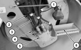
2. Remove hose assemblies (3). Disconnect harness assemblies (2). Remove piston motor (vibratory) (5).
3. Remove bolts (1).
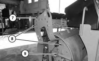
4. Remove support bolts (4) and step assembly (6).
Illustration 2
5. Attach a suitable lifting device to support assembly (7). The weight of support assembly (7) is approximately 150 kg (331 lb).
6. Remove bolts (8) and support assembly (7).
7. Remove drum (9). The weight of drum (9) is approximately 2000 kg (4400 lb).
Installation Procedure
1. Install drum (9) in the reverse order of removal.
a. Apply Tooling (A) to bolts (4). Copyright 1993 - 2025 Caterpillar Inc. All Rights Reserved.
Product: COMPACTOR
Model: CD10 COMPACTOR J6B
Configuration: CD10 Asphalt Compactor J6B00001-UP (MACHINE) POWERED BY C3.4B Engine
Disassembly and Assembly
CD8 and CD10 Vibratory Asphalt Compactors Machine Systems
Media Number -M0079205-03
Publication Date -01/09/2015 Date Updated -14/08/2019
Drum - Remove and Install - Split Drum
SMCS - 6605-010
Removal Procedure Table 1
Required Tools
Tool Part Number Part Description Qty
A - Loctite 242 -
Start By:
a. Release system pressure.
b. Engage steering lock.
c. Remove front scrapper.
Personal injury can result from hydraulic oil pressure and hot oil.
Hydraulic oil pressure can remain in the hydraulic system after the engine has been stopped. Serious injury can be caused if this pressure is not released before any service is done on the hydraulic system.
Make sure all of the work tools have been lowered to the ground, and the oil is cool before removing any components or lines. Remove the oil filler cap only when the engine is stopped, and the filler cap is cool enough to touch with your bare hand.
i04821845
1. Drain the hydraulic oil from the hydraulic tank into a suitable container for storage or disposal. Refer to Operation and Maintenance Manualfor the correct procedure for the correct draining and filling procedures.
2. Insure machine is on a flat level surface before drum is removed.
Illustration 1
g02946817
3. Disconnect hose assemblies (1). Disconnect harness assembly (2).
Illustration 2
g02946860
4. Remove hose assemblies (3). Disconnect harness assemblies (4).
3
5. Remove bolts (5). Disconnect harness assemblies (6). Repeat for other side.
4
6. Raise the front of the machine and place on suitable cribbing under the frame in order to support the weight of the machine. Ensure that the drum maintains contact with the ground.
5
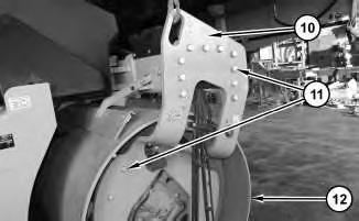
7. Attach a suitable lifting device to bracket (7). The weight of bracket (7) is approximately 200 kg (441 lb). Remove bolts (8) and step (9). Remove bracket (7).
Illustration
g02946336
Illustration
g02947159
8. Attach a suitable lifting device to bracket (10). The weight of bracket (10) is approximately 200 kg (441 lb). Remove bolts (11). Remove bracket (10).
9. Remove drum (12). The weight of drum (12) is approximately 2000 kg (4400 lb).
Installation Procedure
1. Install drum (12) in the reverse order of removal.
a. Apply Tooling (A) to bolts (5).
b. Apply Tooling (A) to bolts (8).
c. Apply Tooling (A) to bolts (11).
Copyright 1993 - 2025 Caterpillar Inc.
Rights Reserved.
Network For SIS Licensees. Mon Feb 24 23:09:38 UTC+0700 2025
Product: COMPACTOR
Model: CD10 COMPACTOR J6B
Configuration: CD10 Asphalt Compactor J6B00001-UP (MACHINE) POWERED BY C3.4B Engine
Disassembly and Assembly
CD8 and CD10 Vibratory Asphalt Compactors Machine Systems
Media Number -M0079205-03
Publication Date -01/09/2015 Date Updated -14/08/2019
Drum Scraper - Remove and Install
SMCS - 6607-010
Removal Procedure
Start By:
a. Engage steering frame lock.
Illustration 1
g02894998
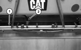
1. Attach a suitable lifting device to front scraper assembly (1). The weight of front scrapper assembly (1) is approximately 68 kg (150 lb).
2. Disconnect hose (2).
i04823173