

Note: Use Bookmarks panel to navigate
Note: Use Bookmarks panel to navigate
For some reason if link does not work download this pdf and then click

Product: COMPACTOR
Model: CC-24B COMPACTOR HCB
Configuration: CC24B Compactor HCB00001-UP (MACHINE) POWERED BY C1.5 Engine
Disassembly and Assembly
C1.1, C1.5 and C2.2 Engines for Caterpillar Built Machines
Media Number -KENR8103-03 Publication Date -01/02/2015 Date Updated -09/06/2016
SMCS - 1405-010
S/N - CAA1-UP
S/N - CMY1-UP
Hot engine components can cause injury from burns. Before performing maintenance on the engine, allow the engine and the components to cool.
1. Open the engine enclosure.
2. Turn the disconnect switch to the OFF position.
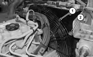
Illustration 1
3. Remove bolts (2) and fan guard (1).
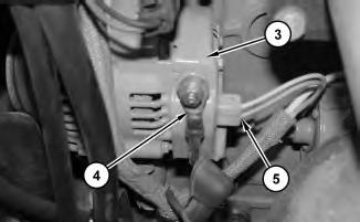
Illustration 2
g01381783
4. Disconnect harness assembly (5) from alternator (3).
5. Remove the nut and remove cable assembly (4) from alternator (3).
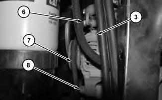
Illustration 3
g01381779
6. Loosen bolt (6) and bolt (8). Remove V-belt (7) from alternator (3). Remove bolt (6), bolt (8), and alternator (3).
4
1. Install alternator (3). Install bolt (8) and bolt (6) loosely. Install V-belt (7) on alternator (3). Refer to Operation and Maintenance Manual for the correct V-belt tension. Tighten bolt (8) and bolt (6).
Illustration 5
g01381783
2. Install cable assembly (4) and the nut to alternator (3).
3. Connect harness assembly (5) to alternator (3).
Illustration 6
g01381781
4. Install fan guard (1) and bolts (2).
5. Turn the disconnect switch to the ON position.
6. Close the engine enclosure. Copyright 1993 - 2025 Caterpillar Inc.
Rights Reserved.
Network For SIS Licensees. Wed Apr 16 23:30:00 UTC+0700 2025

Product: COMPACTOR
Model: CC-24B COMPACTOR HCB
Configuration: CC24B Compactor HCB00001-UP (MACHINE) POWERED BY C1.5 Engine
Disassembly and Assembly
C1.1, C1.5 and C2.2 Engines for Caterpillar Built Machines
Media Number -KENR8103-03
Publication Date -01/02/2015
SMCS - 1405-010
Start By:
Date Updated -09/06/2016
i02848884
a. Remove the V-Belts. Refer to Disassembly and Assembly, "V-Belts - Remove and Install".
Note: Disconnect all electrical connections to the alternator before proceeding. Mark the connections or identify the connections for future installation.
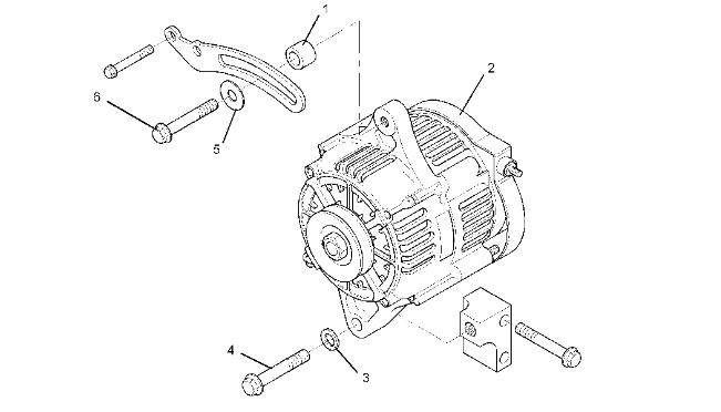
1. Remove the setscrew (6), the washer (5) and the spacer (1) from the alternator (2).
2. Remove the setscrew (4) and the washer (3) that fastens the alternator (2) to the engine.
3. Remove the alternator (2) from the engine.
Start By:
a. Remove the V-Belts. Refer to Disassembly and Assembly, "V-Belts - Remove and Install".
Note: Disconnect all electrical connections to the alternator before proceeding. Mark the connections or identify the connections for future installation.
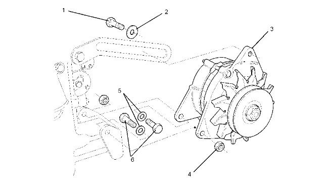
Illustration 2
Typical example
1. Remove the setscrew (1) and the washer (2) from the alternator (3).
g01110800
2. Remove the two bolts (6), the two washers (5) and the two nuts (4) that fasten the alternator (3) to the engine.
3. Remove the alternator (3) from the engine.
Start By:
a. Remove the V-Belts. Refer to Disassembly and Assembly, "V-Belts - Remove and Install".
Note: Disconnect all electrical connections to the alternator before proceeding. Mark the connections or identify the connections for future installation.



3
Typical example
1. Remove the setscrew (2) and the washer (1) from the alternator (3).
2. Remove the bolt (4), the washer (5) and the nut (6) that fastens the alternator (3) to the engine.
3. Remove the alternator (3) from the engine.
Installation Procedure for the 40 AMP Alternator


Illustration 4 g01122919
Typical example
1. Position the alternator (2) on the engine.
2. Install the setscrew (4) and the washer (3) that fastens the alternator (2) to the engine.
3. Install the setscrew (6), the washer (5) and the spacer (1) to the alternator (2).
4. Hand tighten the setscrew (4) and the setscrew (6) on the alternator (2).
Note: When you install the alternator, ensure that the alternator pulley is in alignment with the crankshaft pulley within one degree.
Note: Reconnect all electrical connections to the alternator before operating the engine.
End By:
a. Install the V-Belts. Refer to Disassembly and Assembly, "V-Belts - Remove and Install".
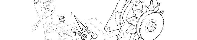

Illustration 5 g01110800
Typical example
1. Position the alternator (3) on the engine.
2. Install the two bolts (6), the two washers (5) and the two nuts (4) that fasten the alternator (3) on the engine.
3. Install the setscrew (1) and the washer (2) to the alternator (3).
4. Hand tighten the two bolts (6), the two nuts (4) and the setscrew (1) on the alternator (3) .
Note: When you install the alternator, ensure that the alternator pulley is in alignment with the crankshaft pulley within one degree.
Note: Reconnect all electrical connections to the alternator before operating the engine.
End By:
a. Install the V-Belts. Refer to Disassembly and Assembly, "V-Belts - Remove and Install".

Illustration 6
Typical example
1. Position the alternator (3) on the engine.
2. Install the bolt (4), the washer (5) and the nut (6) that fastens the alternator (3) to the engine.
3. Install the setscrew (2) and the washer (1) to the alternator (3).
4. Hand tighten the bolt (4), the nut (6) and the setscrew (2) on the alternator (3).
Note: When you install the alternator, ensure that the alternator pulley is in alignment with the crankshaft pulley within one degree.
Note: Reconnect all electrical connections to the alternator before operating the engine.
End By:
a. Install the V-Belts. Refer to Disassembly and Assembly, "V-Belts - Remove and Install".
1993 - 2025 Caterpillar Inc.
For SIS Licensees. Wed Apr 16 23:30:15 UTC+0700 2025
Product: COMPACTOR
Model: CC-24B COMPACTOR HCB
Configuration: CC24B Compactor HCB00001-UP (MACHINE) POWERED BY C1.5 Engine
Disassembly and Assembly
C1.1, C1.5 and C2.2 Engines for Caterpillar Built Machines
Media Number -KENR8103-03
Publication Date -01/02/2015 Date Updated -09/06/2016
SMCS - 1405-010
Removal Procedure
Hot engine components can cause injury from burns. Before performing maintenance on the engine, allow the engine and the components to cool.
1. Open the engine enclosure.
2. Put identification marks on all of the harness assemblies for installation purposes.
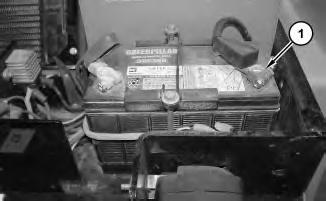
Illustration 1
g01309892
3. Disconnect negative battery cable assembly (1) from the battery.
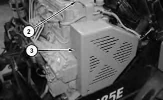
Illustration 2
4. Remove bolts (2) and guard (3).
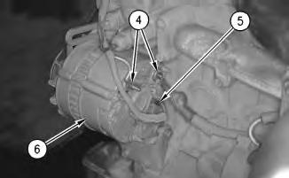
Illustration 3
g00620482
5. Disconnect harness assemblies (4) and (5) from alternator (6).
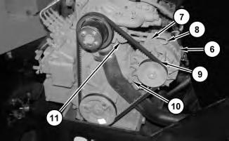
Illustration 4
g01309916
6. Loosen bolt (7). Move alternator (6) toward the engine in order to release the tension on belt (9). Remove bolt (7) from alternator (6).
7. Remove belt (9) from the alternator pulley.
Note: It may be necessary to remove bolt (11), which fastens tensioner (8), in order to remove belt (9).
8. Remove bolt (10). Remove alternator (6) from the alternator mounting bracket.
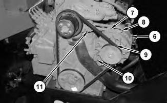
Illustration 5
g01309916
1. Position alternator (6) on the alternator mounting bracket. Install bolt (10). Do not tighten bolt (10) at this time.
2. Install belt (9) on the alternator pulley.
3. Install tensioner (8) and bolt (11). Install bolt (7). Do not tighten bolt (7) at this time.
4. Adjust the belt tension. Refer to Operation and Maintenance Manual for the correct procedure.
5. Tighten bolt (7) and bolt (10) to a torque of 50 ± 5 N·m (37 ± 4 lb ft).
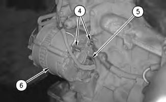
Illustration 6
g00620482
6. Connect harness assemblies (4) and (5) to alternator (6).
7. Install guard (3) and bolts (2).
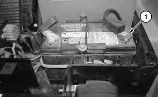
8. Connect negative battery cable (1).
9. Close the engine enclosure.
Copyright 1993 - 2025 Caterpillar Inc. All Rights Reserved. Private Network For SIS Licensees.
Wed Apr 16 23:29:41 UTC+0700 2025
Product: COMPACTOR
Model: CC-24B COMPACTOR HCB
Configuration: CC24B Compactor HCB00001-UP (MACHINE) POWERED BY C1.5 Engine
Disassembly and Assembly
C1.1, C1.5 and C2.2 Engines for Caterpillar Built Machines
Media Number -KENR8103-03
SMCS - 1203-535; 1219-535
Measurement Procedure Table 1
Required Tools Tool
Plastic Gauge (Green)
Plastic Gauge (Red)
Plastic Gauge (Blue)
to 0.229 mm (0.004 to 0.009 inch)
Plastic Gauge (Yellow) 0.230 to 0.510 mm (0.009 to 0.020 inch)
Keep all parts clean from contaminants.
Contaminants may cause rapid wear and shortened component life.
Note: Caterpillar does not recommend the checking of the actual bearing clearances particularly on small engines. This is because of the possibility of obtaining inaccurate results and the possibility of damaging the bearing or the journal surfaces. Each Caterpillar engine bearing is quality checked for specific wall thickness.
Note: The measurements should be within specifications and the correct bearings should be used. If the crankshaft journals and the bores for the block and the rods were measured during disassembly, no further checks are necessary. However, if the technician still wants to measure the bearing clearances, Tooling (A) is an acceptable method. Tooling (A) is less accurate on journals with small diameters if clearances are less than 0.10 mm (0.004 inch).
Lead wire, shim stock or a dial bore gauge can damage the bearing surfaces.
The technician must be very careful to use Tooling (A) correctly. The following points must be remembered:
• Ensure that the backs of the bearings and the bores are clean and dry.
• Ensure that the bearing locking tabs are properly seated in the tab grooves.
• The crankshaft must be free of oil at the contact points of Tooling (A).
1. Put a piece of Tooling (A) on the crown of the bearing that is in the cap.
Note: Do not allow Tooling (A) to extend over the edge of the bearing.
2. Use the correct torque-turn specifications in order to install the bearing cap. Do not use an impact wrench. Be careful not to dislodge the bearing when the cap is installed.
Note: Do not turn the crankshaft when Tooling (A) is installed.
3. Carefully remove the cap, but do not remove Tooling (A). Measure the width of Tooling (A) while Tooling (A) is in the bearing cap or on the crankshaft journal. Refer to Illustration 1.
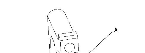


Illustration 1 g00953605
Typical Example
4. Remove all of Tooling (A) before you install the bearing cap.
Note: When Tooling (A) is used, the readings can sometimes be unclear. For example, all parts of Tooling (A) are not the same width. Measure the major width in order to ensure that the parts are within the specification range. Refer to Specifications Manual, "Connecting Rod Bearing Journal" and Specifications Manual, "Main Bearing Journal" for the correct clearances. Copyright 1993 - 2025 Caterpillar Inc. All Rights Reserved.
Wed Apr 16 23:27:28 UTC+0700 2025
Product: COMPACTOR
Model: CC-24B COMPACTOR HCB
Configuration: CC24B Compactor HCB00001-UP (MACHINE) POWERED BY C1.5 Engine
Disassembly and Assembly
C1.1, C1.5 and C2.2 Engines for Caterpillar Built Machines
Media Number -KENR8103-03
SMCS - 1210-016
Procedure
Publication Date -01/02/2015
Date Updated -09/06/2016
NOTICE
Keep all parts clean from contaminants.
Contaminants may cause rapid wear and shortened component life.
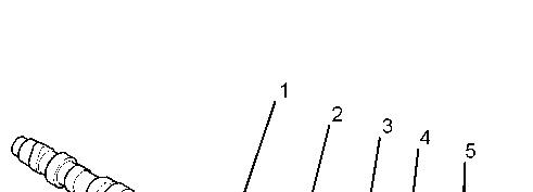
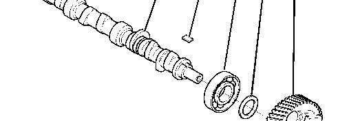

Illustration 1 g01113616
Typical example
1. Ensure that the camshaft (1) is clean. Lubricate the front end of the camshaft with clean engine oil. Use a suitable press to install the front camshaft bearing (3) to the camshaft.
Note: Ensure that the camshaft bearing (3) is installed in the correct orientation. The camshaft bearing should be pressed squarely onto the camshaft or damage to the bearing may occur.
2. Install the spacer (4) and the woodruff key (2) to the camshaft (1).
3. Align the camshaft gear (5) with the woodruff key (2) on the camshaft (1). Use a suitable press to install the camshaft gear to the camshaft.
Note: The camshaft gear should be positioned on a suitable support in order to prevent damage to the governor flyweights during installation.
End By:
a. Install the camshaft assembly. Refer to Disassembly and Assembly, "Camshaft - Install".
Product: COMPACTOR
Model: CC-24B COMPACTOR HCB
Configuration: CC24B Compactor HCB00001-UP (MACHINE) POWERED BY C1.5 Engine
Disassembly and Assembly
C1.1, C1.5 and C2.2 Engines for Caterpillar Built Machines
Media Number -KENR8103-03
Publication Date -01/02/2015
SMCS - 1210-015
Disassembly Procedure
Start By:
Date Updated -09/06/2016
a. Remove the camshaft assembly. Refer to Disassembly and Assembly, "CamshaftRemove".
NOTICE
Keep all parts clean from contaminants.
Contaminants may cause rapid wear and shortened component life.
Illustration 1 g01113616
Typical example
1. Use a suitable puller to remove the camshaft gear (5) from the camshaft (1).
Note: The camshaft gear should be positioned on a suitable support in order to prevent damage to the governor flyweights during disassembly.
2. Remove the spacer (4) and the woodruff key (2) from the camshaft (1).
3. Use a suitable puller to remove the front camshaft bearing (3) from the camshaft (1).
Note: Identify the orientation of the camshaft bearing (3) for installation.
4. Inspect all of the components for wear or damage. Replace any components that are worn or damaged.
Copyright 1993 - 2025 Caterpillar Inc.
Network For SIS Licensees. Wed Apr 16 23:22:58 UTC+0700 2025
Product: COMPACTOR
Model: CC-24B COMPACTOR HCB
Configuration: CC24B Compactor HCB00001-UP (MACHINE) POWERED BY C1.5 Engine
Disassembly and Assembly
C1.1, C1.5 and C2.2 Engines for Caterpillar Built Machines
Media Number -KENR8103-03
Publication Date -01/02/2015
SMCS - 1210-012
Installation Procedure NOTICE
Keep all parts clean from contaminants.
Date Updated -09/06/2016
Contaminants may cause rapid wear and shortened component life.
1. Make sure that the camshaft is clean. Lubricate the camshaft with clean engine oil.
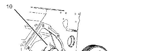
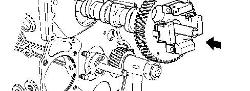

Illustration 1 g01129587
Typical example
2. Carefully install camshaft assembly (10) into the engine cylinder block (11). Be careful not to damage the lobes of the camshaft or the camshaft bearings.
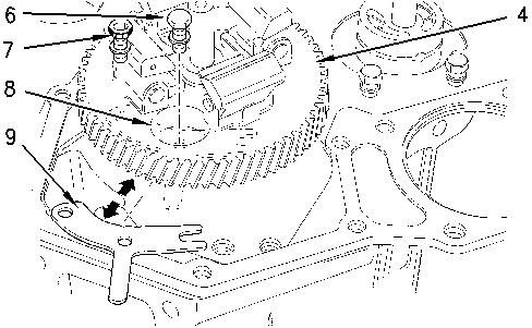
Illustration 2 g00828468
Typical example
3. Install camshaft retainer (9).
Note: The two cylinder and the three cylinder engines have a different camshaft retainer (9) and different fasteners (6) and (7), to the four cylinder engines. The removal procedure is similar for all models.
4. Align the holes in camshaft retainer (9) with the holes in cylinder block (10).
Install the outer setscrew (6) and install the allen head screw (7).
Torque both fasteners to 11 N·m (8 lb ft).
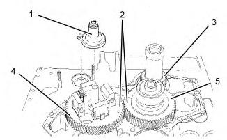
Illustration 3 g01372151
Typical example
5. When you install the idler gear, make sure that timing marks (2) are aligned on the following components:
Crankshaft gear (3)
Camshaft gear (4)
Idler gear (5)
6. Install idler gear (5). Refer to Disassembly and Assembly, "Engine Oil Pump - Install".
7. Install slider (1) to camshaft (4).
Note: Make sure that the notch on the base of slider (1) is engaged on the pin of camshaft gear (4).
End By:
a. Install the engine front housing. Refer to Disassembly and Assembly, "Housing (Front)Install".
b. Install the fuel priming pump. Refer to Disassembly and Assembly, "Fuel Priming PumpInstall".
c. Install the lifters. Refer to Disassembly and Assembly, "Lifter Group- Remove and Install".
For some reason if link does not work download this pdf and then click