DOWNLOAD LINK
For some reason if link does not work download this pdf and then click
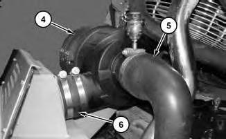
Illustration 4
5. Loosen the clamp and remove tube (5) from air cleaner housing (4) .
6. Loosen the clamp and remove tube (6) from air cleaner housing (4) .
7. Remove the bolts and remove air cleaner housing (4) from the machine.
Installation Procedure
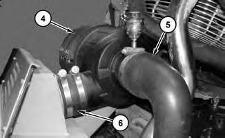
Illustration 5
1. Install air cleaner housing (4) and the bolts.
2. Install tube (6) on air cleaner housing (4) and tighten the clamp.
3. Install tube (5) on air cleaner housing (4) and tighten the clamp.
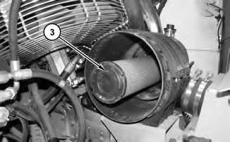
Illustration 6
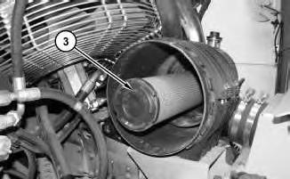
4. Install secondary air filter element (3) .
g01637355
g01637354
7
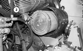
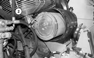
5. Install primary air filter element (2) .
8
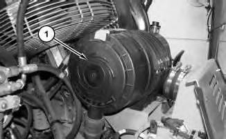
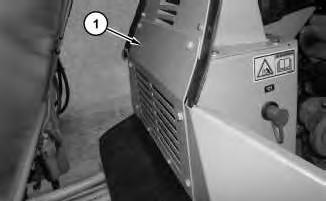
6. Install cover (1) .
7. Close the engine enclosure.
Copyright 1993 - 2024 Caterpillar Inc. All Rights Reserved. Private Network For SIS Licensees. Fri Jul 19 22:54:38 UTC+0530 2024
Illustration
g01637353
Illustration
g01637351
Product: VIBRATORY COMPACTOR
Model: CB-54 VIBRATORY COMPACTOR K3J
Configuration: CB54 Compactor K3J00001-UP (MACHINE) POWERED BY C4.4 Engine
Disassembly and Assembly
CB54 and CB64 Asphalt Compactors Engine Supplement
Media Number -KENR5996-01
Publication Date -01/04/2013
Alternator - Remove and Install
SMCS - 1405-010
Removal Procedure
Date Updated -15/04/2013
Hot engine components can cause injury from burns. Before performing maintenance on the engine, allow the engine and the components to cool.
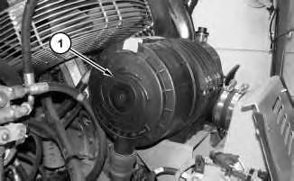
1. Open the engine enclosure.
2. Turn the disconnect switch to the OFF position.
i03214826
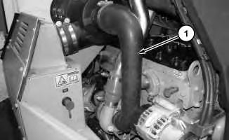
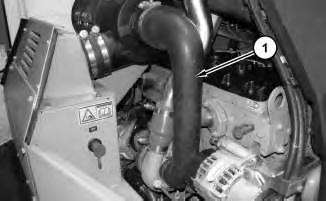
3. Loosen the clamps from both ends of tube (1) and remove tube (1) .
2
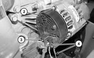
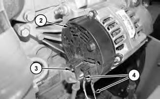
4. Remove the nut and disconnect cable assembly (3) from alternator (2) .
5. Remove the nuts and disconnect harness assemblies (4) from alternator (2) .
3
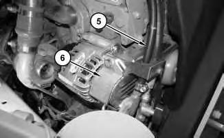
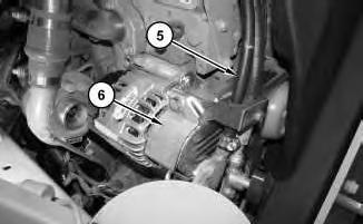
6. Remove the bolts and bracket (6) .
7. Move hose assemblies (5) out of the way.
Illustration
g01641538
Illustration
g01641539
4
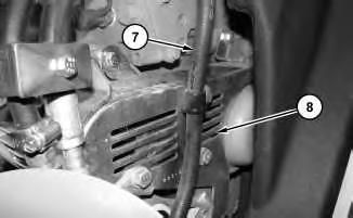
8. Remove the bolt and move hose assembly (7) out of the way.
9. Remove the bolts and guard (8) .
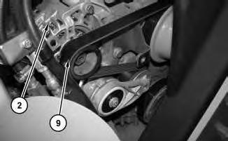
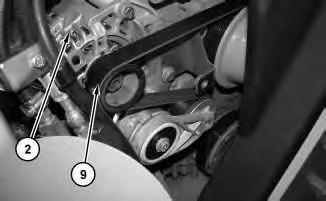
10. Remove belt (9) from alternator (2) .
Illustration
g01641540
Illustration 5
g01641542
Illustration 6
g01641543
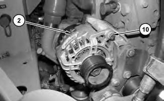
11. Remove bolts (10) and alternator (2) from the engine.
Installation Procedure
Illustration 7
1. Install alternator (2) on the engine and bolts (10) .
8
2. Install belt (9) on alternator (2) .
g01641543
Illustration
g01641542
3. Install guard (8) and the bolts.
4. Reposition hose assembly (7) and install the bolt.
5. Reposition hose assemblies (5) .
6. Install the bolts and bracket (6) .
Illustration 9
g01641540
Illustration 10
g01641539
7. Connect harness assemblies (4) to alternator (2) and the nuts.
8. Connect cable assembly (3) to alternator (2) and the nut.
Illustration 12
9. Install tube (1) and tighten the clamps on both ends of tube (1) .
10. Turn the disconnect switch to the ON position.
11. Close the engine enclosure.
Product: VIBRATORY COMPACTOR
Model: CB-54 VIBRATORY COMPACTOR K3J
Configuration: CB54 Compactor K3J00001-UP (MACHINE) POWERED BY C4.4 Engine
Disassembly and Assembly
CB54 and CB64 Asphalt Compactors Engine Supplement
Media Number -KENR5996-01
Publication Date -01/04/2013
Battery - Remove and Install
SMCS - 1401-010
Removal Procedure
Date Updated -15/04/2013
1. Open the engine enclosure. Turn the battery disconnect switch to the OFF position.
Illustration 1
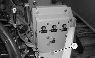
2. Remove the bolts and plate (1) .
g01642223
i03214827
2
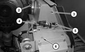
3. Loosen clamps (2) .
4. Remove the bolts, clips (5), and harness assembly (4) .
5. Remove bolts (6) and plate assembly (3) .
3
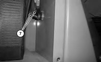
6. Remove the nut and harness assemblies (7) .
Illustration
g01642224
Illustration
g01642227
4
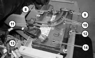
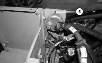
7. Loosen the nut and disconnect negative cable assembly (13) .
8. Loosen the nut and disconnect positive cable assembly (8) .
9. Remove clamps (9) and (11) .
10. Place cable assemblies (10) out of the way.
11. Loosen the nuts and remove hold down bracket (12) .
12. Remove battery (14). Use two people to remove battery (14). The weight of battery (14) is approximately 27 kg (60 lb).
Installation Procedure
Illustration 5
g01642228
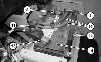
1. Install battery (14). Use two people to install battery (14). The weight of battery (14) is approximately 27 kg (60 lb).
2. Install hold down bracket (12) and tighten the nuts.
3. Place cable assemblies (10) into position.
4. Install clamps (9) and (11) .
5. Connect positive cable assembly (8) and tighten the nut.
6. Connect negative cable assembly (13) and tighten the nut.
8.
9.
10.
6
Illustration
g01642227
7. Install harness assemblies (7) and the nut.
Illustration 7
g01642224
Install plate assembly (3) and bolts (6) .
Install harness assembly (4), clips (5), and the bolts.
Tighten clamps (2) .
11. Install plate (1) and the bolts.
12. Turn the battery disconnect switch to the ON position. Close the engine enclosure. Copyright 1993 - 2024 Caterpillar Inc. All Rights Reserved. Private Network For SIS Licensees. Fri Jul 19 22:55:25 UTC+0530 2024
Product: VIBRATORY COMPACTOR
Model: CB-54 VIBRATORY COMPACTOR K3J
Configuration: CB54 Compactor K3J00001-UP (MACHINE) POWERED BY C4.4 Engine
Disassembly and Assembly
CB54 and CB64 Asphalt Compactors Engine Supplement
Media Number -KENR5996-01 Publication Date -01/04/2013 Date Updated -15/04/2013
Electric Starting Motor - Remove and Install
SMCS - 1453-010
S/N - CB51-UP
S/N - K3J1-UP
Removal Procedure
Hot engine components can cause injury from burns. Before performing maintenance on the engine, allow the engine and the components to cool.
Note: Put identification marks on all hoses, on all hose assemblies, on all wires, and on all tube assemblies for installation purposes. Plug all hose assemblies and all tube assemblies. This helps to prevent fluid loss, and this helps to keep contaminants from entering the system.
1. Open the engine enclosure and turn the battery disconnect switch to the OFF position.
i03214828
1
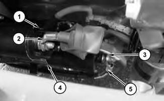
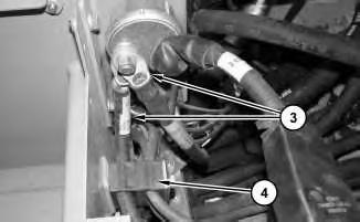
2. Remove the nut and harness assembly (1) from electric starting motor (4) .
3. Remove the nut and cable assembly (2) from electric starting motor (4) .
4. Remove the nut, ground strap (3), and cable assembly (5) from electric starting motor (4) .
2
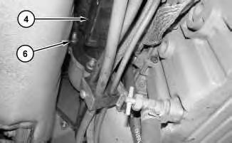
5. Remove nuts (6) and electric starting motor (4) .
Installation Procedure
Illustration
g01641784
Illustration
g01641785
Illustration 3
1. Install electric starting motor (4) and nuts (6) .
Illustration 4
g01641784
2. Install cable assembly (5), ground strap (3), and the nut to electric starting motor (4) .
3. Install cable assembly (2) and the nut to electric starting motor (4) .
4. Install harness assembly (1) and the nut to electric starting motor (4) .
5. Turn the battery disconnect switch to the ON position. Close the engine enclosure. Copyright 1993 - 2024 Caterpillar Inc.
Rights Reserved.
Network For SIS Licensees. Fri Jul 19 22:56:02 UTC+0530 2024
g01641785
Product: VIBRATORY COMPACTOR
Model: CB-54 VIBRATORY COMPACTOR K3J
Configuration: CB54 Compactor K3J00001-UP (MACHINE) POWERED BY C4.4 Engine
Disassembly and Assembly
CB54 and CB64 Asphalt Compactors Engine Supplement
Media Number -KENR5996-01
Publication Date -01/04/2013
Engine - Install
SMCS - 1000-012
Installation Procedure
Illustration 1
Date Updated -15/04/2013
g01644826
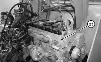
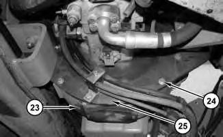
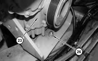
1. Attach a suitable lifting device to engine (23). The weight of engine (23) is approximately 335 kg (740 lb). Install engine (23) .
i03214830
Illustration 2
2. Connect engine (23) to pump drive (25). Install bolts (24) .
Illustration 3
g01645737
3. Install nut (26). Remove the lifting device from engine (23) .
Illustration 4
g01644825
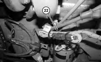
4. Place harness assembly (22) into position and install the cable straps.
g01644827
5
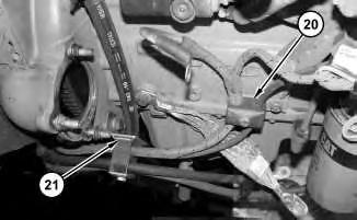
5. Place clamps (20) and (21) into position and install the bolts.
6
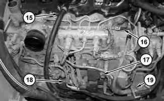
6. Install clamp (19) and the bolt.
7. Install harness assembly (16) and the nut.
8. Connect harness assembly (17) .
9. Connect hose assembly (18) .
10. Install hose (15) and tighten the clamp.
Illustration
g01644823
Illustration
g01644813
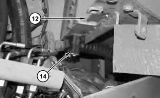
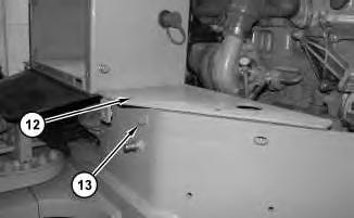
11. Install plate assembly (12). Raise plate assembly (12) and place suitable blocks under plate assembly (12). Install the harness assembly, clamp (14), and the bolts to plate assembly (12) .
12. Raise plate assembly (12) and remove the suitable blocks. Install bolts (13) to both sides of plate assembly (12) .
Illustration 7
g01644762
Illustration 8
g01644760
Illustration 9
g01644759
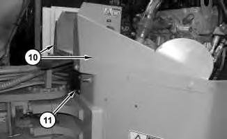
13. Install plates (10) and the bolts to both sides of the machine. Install rubber flashing (11) and the bolts.
10
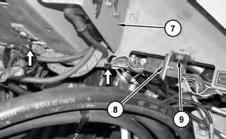
14. Place plate assembly (7) and harness assemblies (8) into position. Install bolt (9) and the cable straps.
11
15. Install bolts (6) .
Illustration
g01644757
Illustration
g01644756
12
16. Place plate assembly (5) into position and install the bolts.
13
17. Install clamps (4) and the bolt.
18. Install cable assemblies (3) and the nut.
14
Illustration
g01644755
Illustration
g01644754
Illustration
g01644737
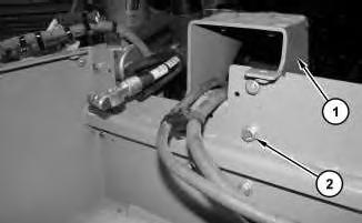
19. Install plate assembly (1) and bolts (2) .
End By:
a. Install the gear pump. Refer to Disassembly and Assembly, "Gear Pump (Charge,Steering)Install".
b. Install the radiator, the aftercooler, and the hydraulic oil cooler. Refer to Disassembly and Assembly, "Radiator, Aftercooler, and Hydraulic Oil Cooler - Remove and Install".
c. Install the muffler. Refer to Disassembly and Assembly, "Muffler - Remove and Install".
d. Install the electric starting motor. Refer to Disassembly and Assembly, "Electric Starting Motor - Remove and Install".
e. Install the alternator. Refer to Disassembly and Assembly, "Alternator - Remove and Install".
f. Install the air cleaner. Refer to Disassembly and Assembly, "Air Cleaner - Remove and Install".
g. Install the battery. Refer to Disassembly and Assembly, "Battery - Remove and Install".
Product: VIBRATORY COMPACTOR
Model: CB-54 VIBRATORY COMPACTOR K3J
Configuration: CB54 Compactor K3J00001-UP (MACHINE) POWERED BY C4.4 Engine
Disassembly and Assembly
CB54 and CB64 Asphalt Compactors Engine Supplement
Media Number -KENR5996-01
Engine - Remove
SMCS - 1000-011
Removal Procedure
Start By:
A. Remove the battery. Refer to Disassembly and Assembly, "Battery - Remove and Install".
B. Remove the air cleaner. Refer to Disassembly and Assembly, "Air Cleaner - Remove and Install".
C. Remove the alternator. Refer to Disassembly and Assembly, "Alternator - Remove and Install".
D. Remove the electric starting motor. Refer to Disassembly and Assembly, "Electric Starting Motor - Remove and Install".
E. Remove the muffler. Refer to Disassembly and Assembly, "Muffler - Remove and Install".
F. Remove the radiator, the aftercooler, and the hydraulic oil cooler. Refer to Disassembly and Assembly, "Radiator, Aftercooler, and Hydraulic Oil Cooler - Remove and Install".
G. Remove the gear pump. Refer to Disassembly and Assembly, "Gear Pump (Charge,Steering) - Remove".
i03214829
This is the sample of the manual click on the download link for complete manual