DOWNLOAD LINK
For some reason if link does not work download this pdf and then click
5. Loosen bolt (7). Move alternator (6) toward the engine in order to release the tension on belt (9). Remove bolt (7) from alternator (6) .
6. Remove belt (9) from the alternator pulley.
Note: It may be necessary to remove bolt (11), which fastens tensioner (8), in order to remove belt (9) .
7. Remove bolt (10). Remove alternator (6) from the alternator mounting bracket.
Installation Procedure
Illustration 5
g01079313
1. Position alternator (6) on the alternator mounting bracket. Install bolt (10). Do not tighten bolt (10) at this time.
2. Install belt (9) on the alternator pulley.
3. Install tensioner (8) and bolt (11). Install bolt (7). Do not tighten bolt (7) at this time.
4. Adjust the belt tension. Refer to Operation and Maintenance Manual for the correct procedure.
5. Tighten bolt (7) and bolt (10) to a torque of 50 ± 5 N·m (37 ± 4 lb ft).
Illustration 6
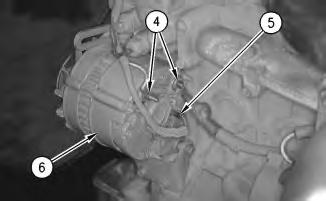
6. Connect harness assemblies (4) and (5) to alternator (6) .
Illustration 7
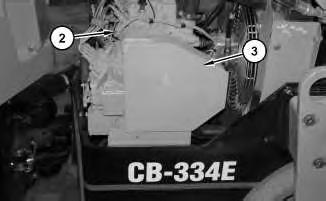
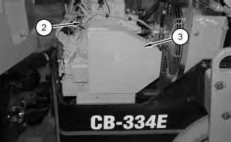
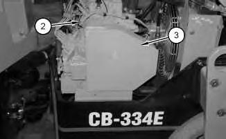
7. Install guard (3) and bolts (2) .
g01079237
Illustration 8
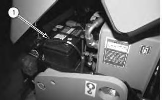
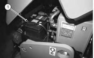
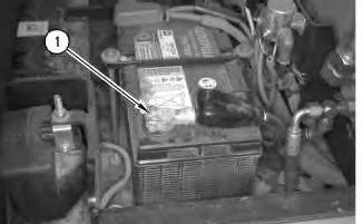
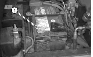
8. Connect negative battery cable (1) .
g00615457
g00620482
9. Close the engine hood.
Network For SIS Licensees. Mon Dec 9 00:47:11 UTC+0530 2024
Product: VIBRATORY COMPACTOR
Model: CB-335E VIBRATORY COMPACTOR C5F
Configuration: CB-334E,CB-335E Vibratory Compactor C5F00001-UP (MACHINE) POWERED BY 3024C Engine
Disassembly and Assembly
CB-334E and CB-335E Vibratory Compactors Engine Supplement
Media Number -KENR3683-00
Publication Date -01/07/2004
Electric Starting Motor - Remove and Install
SMCS - 1453-010
Removal Procedure
1. Open the engine hood.
Note: Put identification marks on all wires for installation purposes.
Illustration 1 g00615457
2. Disconnect negative battery cable (1) .
Date Updated -23/07/2004
i02119423
2
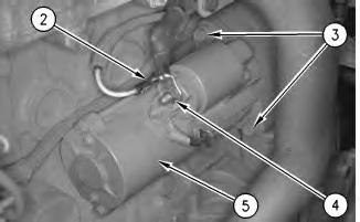
3. Disconnect electrical connector (2) .
4. Disconnect cable assembly (4) .
5. Remove bolts (3) and remove electric starting motor (5) .
Installation Procedure
3
1. Position electric starting motor (5) and install bolts (3) .
2. Connect cable assembly (4) .
3. Connect electrical connector (2) .
Illustration
g00615324
Illustration
g00615324
4. Connect negative battery cable (1) .
5. Close the engine hood.
Copyright 1993 - 2024 Caterpillar Inc. All Rights Reserved. Private Network For SIS Licensees.
Mon Dec 9 00:47:39 UTC+0530 2024
Product: VIBRATORY COMPACTOR
Model: CB-335E VIBRATORY COMPACTOR C5F
Configuration: CB-334E,CB-335E Vibratory Compactor C5F00001-UP (MACHINE) POWERED BY 3024C Engine
Disassembly and Assembly
CB-334E and CB-335E Vibratory Compactors Engine Supplement
Media Number -KENR3683-00 Publication Date -01/07/2004 Date Updated -23/07/2004
Engine - Install
SMCS - 1000-012
Installation Procedure
Table 1
Required Tools
Illustration 1 g01081863
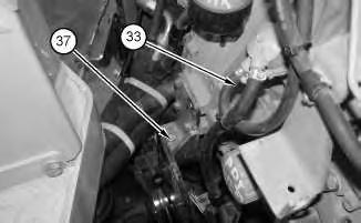
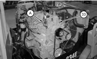
1. Attach a suitable lifting device and Tooling (A) to engine (33). Install the engine in the machine and bolts (37) on both sides of the engine. The weight of the engine is approximately 333 kg (735 lb).
i02125781
Illustration 2
g01081775
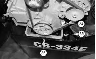
2. Install support bracket (35), bolts (34), and bolt (37) .
Illustration 3
g01081774
3. Remove the suitable lifting device and Tooling (A) from engine (33) .
Illustration 4
g01081757
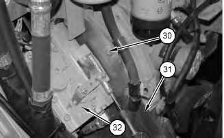
4. Reposition bracket (31) and install bolts (30). Remove the suitable blocking from piston pump (32) .
Illustration 5
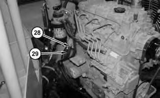
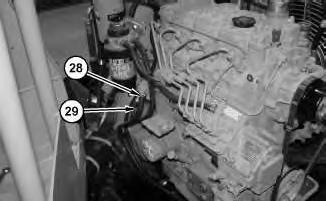
5. Connect hose (29) and tighten clamp (28) .
Illustration 6
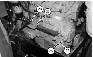
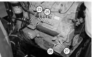
6. Reposition cable assembly (23) and tighten jam nut (25) .
7. Install bracket (27) and bolt (26) .
g01081756
g01081705
7
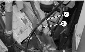
8. Reposition cable assembly (23) and install bolt (24) .
8
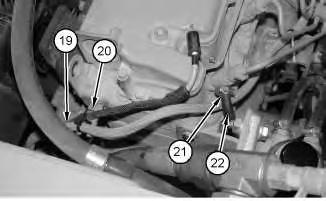
9. Reposition harness assembly (19) and install clamp (20) and the bolt.
10. Connect hose (22) and tighten clamp (21) .
9
Illustration
g01081703
Illustration
g01081702
Illustration
g01081690
11.
.
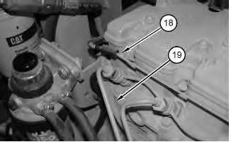
Reposition harness assembly (19). Connect harness assembly (18)
Illustration 10
g01081362
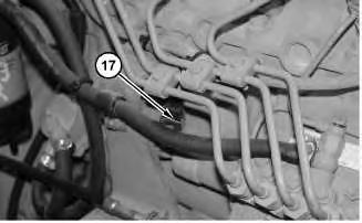
12. Connect harness assembly (17) .
Illustration 11
g01081359
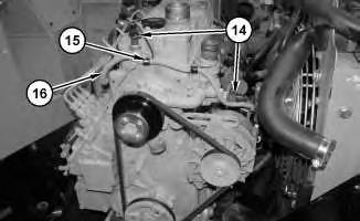
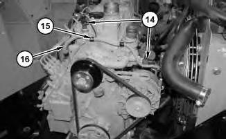
13. Reposition harness assembly (16) and install clamps (15). Connect harness assemblies (14) .
Illustration 12
g01081507
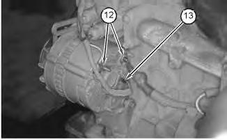
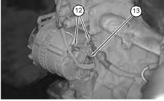
14. Connect harness assemblies (12) on alternator (13) .
Illustration 13
g01081505
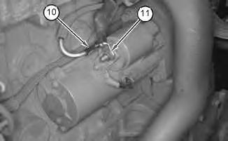
15. Connect cable assemblies (10) on electric starting motor (11) .
Illustration 14
g01081357
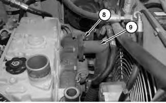
16. Install the gasket, exhaust pipe (9) and bolts (8) .
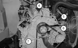
17. Connect hose (6) on the engine and tighten clamp (7) .
18. Connect hose (5) on the engine and tighten clamp (4) .
Install guard (3) and bolts
Illustration 15
g01081146
Illustration 16
g01081143
19.
(2) .
Illustration 17
g00610382
20. Connect battery ground cable (1) on the battery and tighten the clamp.
21. Fill the engine and the radiator with coolant. Refer to Operation and Maintenance Manual for the correct procedure.
End By: Install the engine hood. Refer to Disassembly and Assembly, "Engine Hood - Remove and Install". Copyright 1993 - 2024 Caterpillar Inc.
Product: VIBRATORY COMPACTOR
Model: CB-335E VIBRATORY COMPACTOR C5F
Configuration: CB-334E,CB-335E Vibratory Compactor C5F00001-UP (MACHINE) POWERED BY 3024C Engine
Disassembly and Assembly
CB-334E and CB-335E Vibratory Compactors Engine Supplement
Media Number -KENR3683-00 Publication Date -01/07/2004 Date Updated -23/07/2004
Engine - Remove
SMCS - 1000-011
Removal Procedure Table 1
Required Tools
Start By:
A. Remove the engine hood. Refer to Disassembly and Assembly, "Engine Hood - Remove and Install".
Hot oil and hot components can cause personal injury. Do not allow hot oil or hot components to contact skin.
At operating temperature, the engine coolant is hot and under pressure.
Steam can cause personal injury.
Check the coolant level only after the engine has been stopped and the cooling system pressure cap is cool enough to touch with your bare hand.
Remove the cooling system pressure cap slowly to relieve pressure.
i02120377
Cooling system conditioner contains alkali. Avoid contact with the skin and eyes to prevent personal injury.
NOTICE
Care must be taken to ensure that fluids are contained during performance of inspection, maintenance, testing, adjusting and repair of the product. Be prepared to collect the fluid with suitable containers before opening any compartment or disassembling any component containing fluids.
Refer to Special Publication, NENG2500, "Caterpillar Tools and Shop Products Guide" for tools and supplies suitable to collect and contain fluids on Caterpillar products.
Dispose of all fluids according to local regulations and mandates.
Note: Put identification marks on all lines, on all hoses, on all wires and on all tubes for installation purposes. Plug all lines, all hoses and all tubes. This will help to prevent fluid loss and this will help to keep contaminants from entering the system.
1. Use the petcock and drain hose that is located on the radiator to drain coolant from the radiator and the engine into a suitable container. Refer to Operation and Maintenance Manual for the correct procedure.
Illustration 1
g00610382
2. Loosen the clamp and disconnect battery ground (1) .
2
3
4
Illustration
g01081143
3. Remove bolts (2) and guard (3) .
Illustration
g01081146
4. Loosen clamp (4) and disconnect hose (5) from the engine.
5. Loosen clamp (7) and disconnect hose (6) from the engine.
Illustration
g01081357
6. Remove bolts (8) and the gasket. Move exhaust pipe (9) away from the engine.
5
7. Disconnect cable assemblies (10) from electric starting motor (11) .
6
8. Disconnect harness assemblies (12) from alternator (13) .
Illustration
g01081505
Illustration
g01081507
Illustration 7 g01081359
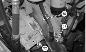
9. Disconnect harness assemblies (14). Remove clamps (15) and move harness assembly (16) out of the way.
Illustration 8
g01081362
10. Disconnect harness assembly (17) from the fuel shutoff solenoid.
Illustration 9
11. Disconnect harness assembly (18) and move harness assembly (19) out of the way.
g01081690
12. Loosen clamp (21) and disconnect hose (22) .
13. Remove the bolt and clamp (20) from the engine. Move harness assembly (19) out of the way.
14. Remove bolt (24) from cable assembly (23) .
Illustration 10
g01081702
Illustration 11
g01081703
Illustration 12 g01081705
15. Remove bolt (26) and bracket (27) from the engine.
16. Loosen jam nut (25) and move cable assembly (23) out of the way.
13
17. Loosen clamp (28) and disconnect hose (29) from the fuel pump.
14
18. Install suitable blocking under piston pump (32). Remove bolts (30) and move bracket (31) out of the way.
Illustration
g01081756
Illustration
g01081757
Illustration 15
g01081774
19. Attach a suitable lifting device and Tooling (A) to engine (33), as shown.
Illustration 16
g01081775
20. Remove bolt (36), bolts (34), and support bracket (35) .
Illustration 17
g01081863
21. Remove bolts (37) from both sides of engine (33). Remove the engine from the machine. The weight of the machine is approximately 333 kg (735 lb).
Copyright 1993 - 2024 Caterpillar Inc. All Rights Reserved. Private Network For SIS Licensees.
Mon Dec 9 00:51:53 UTC+0530 2024
Product: VIBRATORY COMPACTOR
Model: CB-335E VIBRATORY COMPACTOR C5F
Configuration: CB-334E,CB-335E Vibratory Compactor C5F00001-UP (MACHINE) POWERED BY 3024C Engine
Disassembly and Assembly
CB-334E and CB-335E Vibratory Compactors Engine Supplement
Media Number -KENR3683-00
Publication Date -01/07/2004
Date Updated -23/07/2004
Engine Flexible Mounting - Remove and Install
SMCS - 1152-010
Removal Procedure
Start By:
A. Remove the engine. Refer to Disassembly and Assembly, "Engine - Remove".
Illustration 1
g00621567
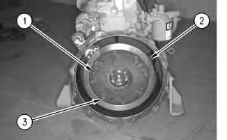
1. Remove bolts (3) and remove nylon flange (1) from flywheel (2) .
Installation Procedure
i02120337
This is the sample of the manual click on the download link for complete manual