
CB-334D VIBRATORY COMPACTOR

Note: Use Bookmarks panel to navigate

Product: VIBRATORY COMPACTOR
Model: CB-334D VIBRATORY COMPACTOR DCZ
Configuration: CB-334D Vibratory Compactor DCZ00001-UP (MACHINE) POWERED BY 3014 Engine
Disassembly and Assembly
Seal Installation
Media Number -UENR3262-00 Publication Date -01/11/2020 Date Updated -30/10/2012
i04905677
O-Ring Seals - Install - RADIAL, FITTING ASSEMBLY ORINGS & OTHER O-RING APPLICATIONS
SMCS - 7555-012
O-RINGS INSTALLED IN STOR/ORFS FITTINGS (FITTING/ADAPTOR ASSEMBLIES)


Commonly used fluid line connectors are:
1. Straight Threaded O-Rings (STOR)
2. O-ring Face Seal (ORFS)
3. Bolt Flanges (SAE Code 61, 62, and CAT Flange)
Radial O-ring seals and conventional face seals are not fluid line connectors.
O-ring sealing depends on proper seating of the seal in the groove, maintaining this condition during assembly of the joint, and proper torque on the connection. Improper assembly practices increase the likelihood of leaking joints.
Assembly Aids - Retention compounds and lubricants must not be used on STOR/ORFS. Applications requiring the use of a retention compound need to be validated for seal compatibility with the retention compound by Caterpillar before use.
Assembly Tooling
O-rings may be installed into a fitting/adapter without the use of a tool however, installing a seal without the use of a tool places the seal at extreme risk of damage. It is recommended that appropriate tooling should be used for the installation of O-rings.
Types of Installation Tooling
This is the sample of the manual click on the download link for complete manual
DOWNLOAD LINK
For some reason if link does not work download this pdf and then click
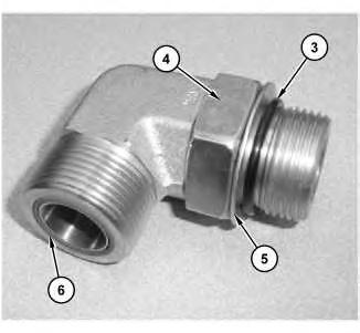
Illustration 3 g03150193
Anatomy of an STOR/ORFS Fitting
(3) STOR O-ring
(4) Nut
(5) Washer
(6) ORFS O-ring
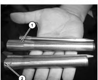
When installing an O-ring over a threaded fitting, it is critical to protect the seal from damage from threads. To assist the assembly and protect the seal, an installation tool must be used shown in Illustration 2. The seal protector slides over the threads and allows for an O-ring to be installed, reducing the risk of a leak due to nicks, cuts, gouges, and twisting of the seal.
Tool Ordering Information
The tooling listed below can be ordered from Caterpillar using the part numbers in Table 1.
Table 1
Fitting Size CAT Part Number
(-3) 336-0739
(-4) 336-0740
(-6) 336-0741
(-8) 336-0742
(-10) 336-0744
(-12) 336-0750
(-14) 336-0767
(-16) 336-0784
(-20) 336-0787
ORFS Insertion Tool
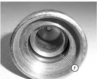
Illustration 4 g03150194
Anatomy of ORFS O-Ring insertion tool
(7) Plunger platform
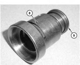
Illustration 5
Anatomy of ORFS O-Ring insertion tool
(8) O-ring slot
(9) Plunger/trigger
g03150195
This tool (Illustration 4) helps to place an O-ring into the fitting groove with minimal risk of damage to the seal.
Tool Ordering Information
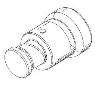
Illustration 6
Typical installer
g03150196
The ORFS insertion tool can be procured as outlined in the "Dealer Service Tools 2006 Catalog": Vehicle System Tool Section. Tool part numbers for ordering are shown in Table 2.
Table 2
Tooling - Possible Damage
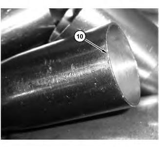
Illustration 7
STOR tooling damage
g03150197
Nicks, material gouges, and chatter marks along tool head. (10) Tool damage
Material damage to the surface in which the seal will ride is typically in the form of missing material, nicks, gouges, and so on, when forced over the cone for proper seal seating. Illustration 7 shows tool damage (10) due to improper storage.
Assembly Tooling - Storage
STOR Installation tooling shall be stored in a manner that will minimize the risk of damage to the outside diameter (shaft).
The best-practice tool storage device is one that will:
• Segregate the tool preventing contact from other tooling.
• Include a soft surface to prevent metal to metal contact.
• Hold the tool at the inner diameter of the cone shaft rather than outside diameter.
• Provide proper tool identification.
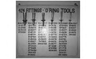
Illustration 8
STOR Installation Tool Storage
g03150198
Illustration 8 shows an example of STOR tooling storage board.
Note: In this example, the tool is being stored using the outer diameter of the shaft, placing tool at risk for damage.
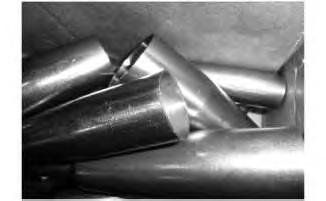
9
Tools stacked on each other
g03150199
Tools shall not be stacked on top of each other (Illustration 9).
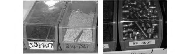
Illustration 10 g03150200
Tools stacked on parts
Tools shall not be stored on top of seals or other parts (Illustration 10).
Tooling - Care
Before using the tooling check the tool for damage. Tools with damage such as nicks, gouges, missing material, or deformation must be replaced immediately.
Tools should be cleaned daily to remove contamination. If contamination is present, use a clean lintfree wipe to remove the debris. To maintain cleanliness and prevent tool damage, storage fixtures should be cleaned as a part of daily 5S activities.
Note: 5S activities refer to CPS For Dealers related to "Sort, Set, Shine, Standardize, and Sustain".
For more details refer to:
https://dealer.cat.com/cda/files/2498665/7/030%20R_Module %2017%205S_Visual% 20Workplace%20v3.ppt
Recommended Cleaning Wipes:
• Chemtool CT Clean 15861 Wipe With Cleaner - Caterpillar Part Number 169-5420 .
• Chemtool Lint-Free Wipes - Caterpillar Part Number 265-2256 .
• Kimtex Lint-Free Polypropylene Towels - Dealer Tools & Supplies: 265-2256 (06179 Kimtech Pure* W5)
• New Pig low-lint wipes, Part Number WIP230, or WIP232 from New Pig Corporation.
TOOLING - INSPECTION
Inspect tooling before use for contamination and damage that in the form of nicks, gouges, or missing material.
Improperly maintained cone and pusher tooling can cause seal damage that may be in the form of cuts, nicks, or tearing of seal. Damage to the seal increases the risk of leaks.
If the cone or pusher is damaged, stop using the tool immediately. Report the issue to the dealer service manager or leadman for immediate replacement.
TOOLING - CRITICAL MAINTENANCE & DAMAGE REPORTING PROCESS
Routine Maintenance - All seal-specific tooling should be placed on a routine maintenance schedule similar to the torque-tooling schedule.
Reporting Damage - A formal reporting process shall be established at every dealer to report damaged tooling.
Replacement Tooling - To reduce the risk of downtime and use of an unapproved tool due to tooling damage, replacement tooling shall be in inventory and available for immediate use. Damaged tools should be replaced immediately since using a damaged tool increases the risk of seal damage or leaks.
ASSEMBLY
ORFS Assembly
When using an O-ring insertion tool:
• Select the appropriate insertion tool
• Verify that the tool is clean and undamaged
ORFS Assembly Procedure
Follow the steps below for proper tool use and assembly of an O-ring into the ORFS groove.
1. Complete a 1-second inspection of the seal, fitting, and tool for damage. A 1 second inspection is a quick visual review of the part and mating component for damage or debris. The 1 second inspection identify part issues before assembling the parts to the components.
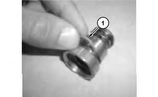
Illustration 11
Insert O-ring
g03150201
2. Insert the O-ring (1) through O-ring slot near top of ORFS insertion tool.
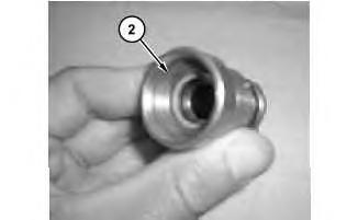
Illustration 12
O-Ring on plunger platform
g03150202
3. Check to see that the O-ring is properly placed on plunger platform (2) .
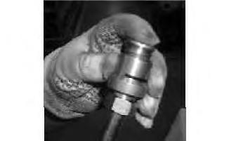
Illustration 13
Plunger pressed
4. Place the ORFS end of the fitting into the tool and depress plunger/trigger.
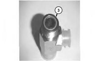
Illustration 14
O-Ring installed
g03150204
5. Verify that O-ring has been properly placed into the groove.
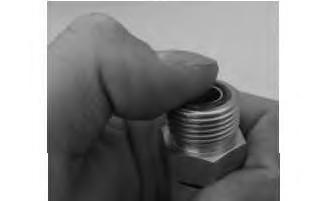
Illustration 15
Finger sweep check
g03150205
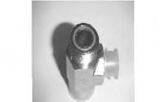
6. Conduct a "finger sweep" by placing a finger on top of the installed seal, while gently pushing down on top of the seal and running the finger around the circumference of the seal.
Note: The finger sweep helps ensure that the seal is properly placed and fully depressed into the groove of the ORFS fitting.
16
Visual inspection
7. Complete a final visual inspection of seal seating after finger sweep.
8. Cap ORFS end for contamination prevention where applicable.
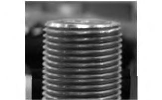
Illustration 17
Fully seated seal
g03150207
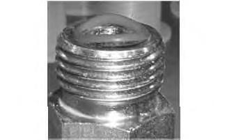
Illustration 18 g03150208
Incorrectly seated seal
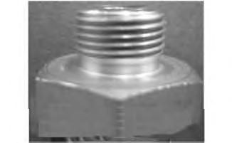
Illustration 19 g03150209
Incorrectly seated seal
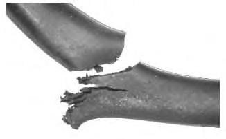
9. Before and after completing the finger sweep, verify that the seal has been properly seated in the groove shown in Illustration 17. Illustration 18 and Illustration 19 demonstrate improperly seated seals.
20
21 g03150211
Pinching damage
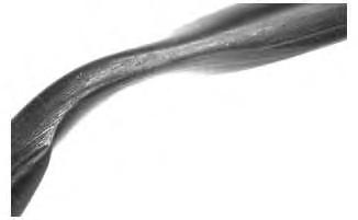
Improper seal installation increases the risk of leaks due to damage by cutting, pinching, or tearing of the seal after assembly (Illustration 20 and 21). Installation damage can increase in size when the connection is pressurized resulting in a leak.
STOR Assembly
Assembly tool must be used to protect the seal from damage due to thread contact. Threads may cut or tear the seal during installation.
When using a STOR installation tool:
• Select the appropriate installation tool.
• Verify that the tool is clean and undamaged.
STOR Assembly Procedures
Follow the steps below for proper tool use and assembly of an O-ring onto the STOR end of a fitting/adapter.
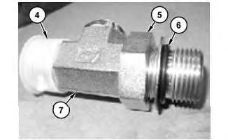
22
STOR locknut position
g03150212
(4) Cap
(5) Fitting body
(6) O-ring
(7) Locknut
1. Complete a 1-second inspection of seal, fitting, and tool for damage. A 1-second inspection is a quick visual review of the part and mating component for damage or debris. The 1 second inspection is to help identify part issues before assembling the parts to the components.
Note: Ensure that the locknut (7) on adjustable STOR fittings is positioned above the O-ring (6) groove as shown in Illustration 22.
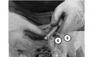
Installation of O-Ring on STOR installation tool
(6) O-ring
(8) Tool
2. Place O-ring (6) over STOR installation tool (8) .
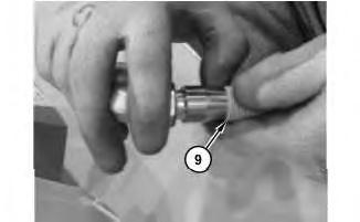
STOR Installation tool on Fitting (10) Fitting thread
3. Place the tool over the fitting thread (10) .
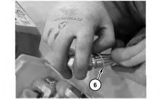
Installation of O-ring in fitting (6) O-ring
4. Place fingers above seal and applying even steady pressure around the seal. Glide seal onto fitting taking care to prevent twisting. If the O-ring (6) is twisted when seated, the O-ring can fail prematurely due to high strain. If a twist is observed, remove the seal and reinstall
Note: In most cases the O-ring (6) that is to be installed onto a fitting should have polytetrafluoroethylene (PTFE) coating. PTFE is a custom coating applied to an O-ring to ease assembly installation.
Note: PTFE is more commonly referred to as Teflon from Dupont.
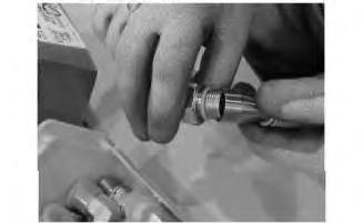
5. Remove tooling from fitting.
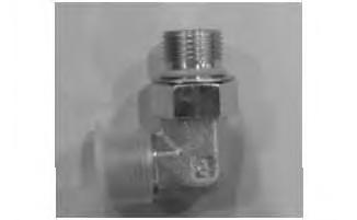
Illustration 27
Inspection of seal seating
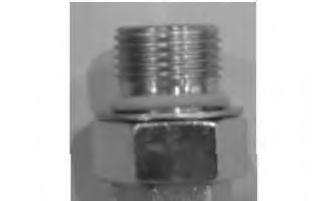
Illustration 28
Seal placement
6. Inspect the placement (seating) of the seal as shown in Illustration 27.
Note: Seal shall be placed over the O-ring groove and resting on washer as shown in Illustration 28.
7. Cap STOR end for contamination prevention where applicable.
Note: If the O-ring is twisted when seated, the O-ring can fail prematurely due to high strain. If a twist is observed, remove the seal and reinstall.
Refer to the Disassembly and Assembly manual for proper tightening specifications of STOR/ORFS into prime product.
Assembly Storage
Assembled product shall be stored in conformance with the Contamination Control Guidelines, PEBJ0002, "Caterpillar Dealer Contamination Control Compliance Guide".
O-RINGS INSTALLED IN FACE SEAL JOINTS (NONADAPTOR APPLICATIONS)
Background
O-ring sealing depends on proper seating of the seal in the groove and maintaining this condition during assembly of the joint. Improper assembly practices increase the likelihood of creating leaks.
Handling
O-rings should not be stretched or twisted beyond what is necessary for installation. O-rings should not be deformed in any manner.
Contact of the O-ring with threads or other sharp objects should be prevented as the contact risks cutting, nicking, or damaging the seal.
Assembly Aid - Retention Compounds
When O-rings and other elastomeric seals are assembled in face grooves that are vertical or inverted, a retention compound may be needed to keep the seal in place.
Caterpillar no longer recommends the use of Petroleum Jelly (Vaseline) to install o-rings or gaskets The reason is that Petroleum Jelly is NOT compatible with all elastomeric (rubber) materials that Caterpillar o-rings and gaskets are made from.
The correct product that should be used for assembly of o-rings is P-80 or Petro Gel Amber. Both of these products are available in the Caterpillar aftermarket and should be used sparingly.
Refer to the list of part numbers below.
• P-80: CAT P/N (NACD): 207-1601
• CAT P/N (EAME): 207-1600
• Petro Gel Amber: CAT P/N: 369-9450 (6 lb can) or 369-9451 (10 oz tube)
Captive grooves (for example: dovetail grooves, and ORFS fittings) have a built-in retention mechanism. Retention compounds or lubricants must not be used for captive grooves.
Retention compound should be stored in a clean, closable container that is kept closed between uses. Consult the Contamination Control Guidelines, PEBJ0002, "Caterpillar Dealer Contamination Control Compliance Guide".
Retention Compound Application
Retention compounds are tacky semi-solids that shall be used only on inverted and vertical O-ring face seal joints.
Application of retention compound directly to the seal does not ensure proper retention in groove. Proper application procedure must be followed.
Do not install a seal into a groove and then apply retention compound to the top surface of the seal The seal will not retain properly in the groove. Retention compounds shall be applied sparingly (peasize beads) into the bottom of the O-ring groove. Use the minimum amount of compound necessary to retain the O-ring during assembly.
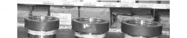
29 g03150219
Incorrect application of retention compound to O-rings
The required amount of retention compound will vary depending upon O-ring size. The work instructions should specify the location and number of retention compound beads to be applied for retention of O-rings. Illustration provides an example of incorrect application of retention compound after seal installation.
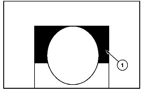
Illustration 30 g03150220
Correct application location for retention compound
Retention compounds (1) shall be applied sparingly (pea-size beads) into the bottom of the O-ring groove as shown in Illustration 30. Use the minimum amount of compound necessary to retain the Oring during assembly. The required amount of retention compound will vary depending upon O-ring size. The work instructions should specify the location and number of retention compound beads to be applied for retention of O-rings.
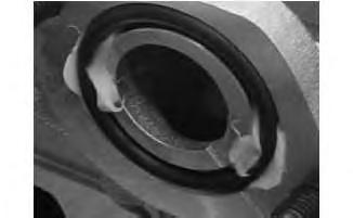
Overfilling the groove (Illustration 31) can cause the seal to be displaced, and may result in the compound getting into areas, such as threads, where the overfilling may have an adverse effect on torque, and incur high cost of assembly.
Do not apply retention compounds with brushes or fingers, which can introduce contamination into the system. Use a proper dispensing method as indicated above for proper application.
Do not apply retention compounds by submerging parts in a bag or box. Follow guidelines outlined in the Contamination Control Guidelines, PEBJ0002, "Caterpillar Dealer Contamination Control Compliance Guide".
Apply retention compounds prior to assembly. Do not preassemble components where retention compounds are used.
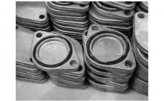
Components preworked and stacked
Do not pre-work components or stack assembled parts as this increases the risk of contamination and seal damage (Illustration 32).
If the retention compound squishes out of a joint or groove, too much has been applied. Use a lintfree wipe to remove excess retention compound and clean surface thoroughly.
Recommended Cleaning
Wipes:
• Chemtool CT Clean 15861 Wipe With Cleaner - Cat Part Number 169-5420 .
• Chemtool Lint-Free Wipes - Cat Part Number 265-2256 .
• Kimtex Lint-Free Polypropylene Towels - Dealer Tools & Supplies: 265-2256 (06179 Kimtech Pure* W5)
• New Pig low-lint wipes, Part Number WIP230, or WIP232 from New Pig Corporation.
Assembly
Visually inspect the mating parts to ensure that all surfaces are clean and free from damage such as nicks or burrs.
When O-rings and other elastomeric seals are assembled in face grooves that are vertical or inverted, a retention compound may be needed to keep the seal in place.
Install the O-ring immediately before the joint is assembled to reduce chances of the O-ring falling out.
Place O-ring in the groove and verify that O-ring is fully placed or seated. Avoid spiraling O-ring during installation.
Install mating face perpendicular to the plane of the groove. Do not slide mating face across the Oring.
Torque all mating component fasteners immediately.
O-RINGS INSTALLED IN RADIAL SEAL JOINTS
Background
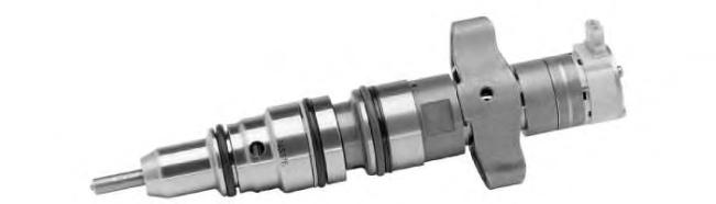
Illustration 33 g03150223
Radial O-ring application on an injector
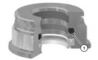
34 g03150224
Seal in bore
(1) Seal
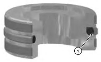
Illustration 35 g03150225
Seal in groove
(1) Seal
Radial sealing depends upon proper seating of the seal in the groove and maintaining this condition during assembly of the joint. Improper assembly practices increase the likelihood of leaking joints. An example of a radial O-ring application is shown in Illustration 33. This document addresses both Seal-in-Bore (Housing) (Illustration 34), and Seal-in-Piston (Shaft) (Illustration 35) designs.
Handling
O-rings should not be stretched or twisted beyond what is necessary for installation. O-rings should not be deformed in any manner.
Contact of the O-ring with threads or other sharp objects should be prevented as the contact risks cutting, nicking, or damaging the seal.
Assembly Aids - Seal Lubricants
When O-rings and other elastomeric seals are assembled into radial seal joints, a lubricant is necessary to reduce spiraling, skiving, cutting, and abrasion. Lubricants also reduce the force required to assemble the joint.
Lubricants shall be stored in properly identified, clean, closable containers that are kept closed between uses. Consult the Contamination Control Guidelines, PEBJ0002, "Caterpillar Dealer Contamination Control Compliance Guide".
Do not use petroleum (Vaseline), any adhesive, or unapproved grease as a lubricant.
Lubricants shall not be used on PTFE coated seals or STOR/ORFS seals.
Assembly Aid - Approved Seal Lubricants
PTFE Coating
PTFE coating is a dry lubricant that should be used on all radial seals. The PTFE coating is added by the manufacturer.
P-80
P-80 may be used as a universal seal lubricant. P-80 is compatible with all sealing elastomers. P-80 dries quickly so P-80 is unlikely to drip out and create the false appearance of a fluid leak.
P-80 must NOT be used on STOR/ORFS seals. P-80 or any other lubricant used on a STOR/ORFS can affect final torque and cause thread stretching.
The use of P-80 on all other PTFE coated seals is acceptable.
Fluid Being Sealed
For oil and fuel joints, the fluid being sealed may be used as a lubricant.
Note: Lubricants must not be used on fluid line connectors (STOR/ORFS) fittings.
Low Pressure AC Line Lubricants
For low-pressure air conditioner lines use the following approved lubricant:
Mineral Seal Oil - McMaster Carr Part No. 3190K281
Lubricant Dispensers
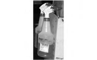
Illustration 36
Spray bottle
g03150226
The recommended method for applying a lubricant is with a small nozzle spray bottle (Illustration 36).
Dispose of lubricant containers that have become internally contaminated.
Lubricant Application
Lubricants are low viscosity fluids that shall be used only on radial seal joints.
Seal lubricant shall always be applied to the primary sealing surface. For example, if the seal is in a groove in the shaft, then the bore is the primary sealing surface. Optionally, lubricant may also be applied to the seal.
Apply wet lubricants at the time of assembly. Do not apply the lubricant in advance.
The application of lubricants shall not introduce debris onto the seal or sealing surface.
Do not apply seal lubricants with brushes or fingers, which can introduce contamination into the system. Avoid the use of brushes that shed fibers.
When using lubricant dispensers such as spray bottles, exercise extreme caution and prevent overspray onto other areas, such as threads, as it may have an adverse effect on torque. Cover all components that must not be lubricated before lubricating. Follow the Contamination Control Guidelines, PEBJ0002, "Caterpillar Dealer Contamination Control Compliance Guide".
Over-spray of lubricants can lead to false leaks. Over-spray of lubricants on threads can adversely affect torque on the connection leading to a loose and leaky joint.
Before using P-80 lubricant, shake well to ensure proper mixing of lubricant.
Apply lubricants only at the time of assembly. Lubricants, especially P-80, may dry up or leak out of the joint if applied in advance.
For low-pressure air conditioner lines, lubricate the O-ring with mineral oil.
Tooling – Inspection
Inspect tooling before use for contamination and damage that in the form of nicks, gouges, or missing material.
Improperly maintained cone and pusher tooling can cause seal damage that may be in the form of cuts, nicks, or tearing of seal. Damage to the seal increases the risk of leaks.
If the cone or pusher is damaged, stop using the tool immediately and report the issue to the supervisor and processor/planner for immediate replacement.
ASSEMBLY TOOLING:
Routine Maintenance - All seal-specific tooling should be placed on a routine maintenance schedule similar to the torque-tooling schedule.
Reporting Damage - A formal reporting process shall be established at every dealer to report damaged tooling.
Replacement Tooling - To reduce the risk of downtime and use of an unapproved tool due to tooling damage, replacement tooling shall be in inventory and available for immediate use. Damaged tools should be replaced immediately since using a damaged tool increases the risk of seal damage or leaks.
Assembly

Illustration 37 g03150227
Cleaning of groove for brake seal
Visually inspect mating parts for contamination or damage (nicks, scratches burrs, and so on). Use a clean lint-free wipe to remove contamination if present from the groove (Illustration 37). Follow the Contamination Control Guidelines, PEBJ0002, "Caterpillar Dealer Contamination Control Compliance Guide".
Install the seal into the groove immediately before the joint is assembled to reduce chances of the seal being damaged during transit or handling.
Place the seal in the groove. Do not stretch or deform the seal any more than is necessary. Do not allow the seal to contact threads or other sharp objects. Verify that the seal is fully seated. Avoid spiraling seal during installation - the seal should be pushed into position rather than rolled. Use an approved assembly aid when appropriate.
For installation of two-piece seals (example: some brake seals) first install the rubber energizer and then install the cap piece over the rubber energizer.
Lubricate the seal with the fluid being sealed before installing seal.
Lubricate the seal prior to assembly to reduce risk of contamination, run-off, or dry out of seal lubricant.
Do NOT install contaminated seals.
Contaminated seals that cannot be removed and reinstalled using the proper assembly techniques must be cleaned thoroughly using a clean lint-free wipe to reduce risk of damage to the seal. Contaminated seals that are removed should be scrapped using the non-conforming material process to prevent risk of contamination to the system.
For groove in bore applications lubricate the inside diameter of the seal.
For groove in piston applications lubricate the outside diameter of the seal.
Take care when inserting the shaft into the bore. Make sure that the mating parts are properly aligned prior to insertion. Assemble at a slow, uniform rate. Do NOT use impact tools such as hammers when installing assemblies using radial seals.
For larger piston/bore diameters (example: brake seals), use a hydraulic press to ensure proper seating of the seal and piston to bore alignment. Consider installing shaft (piston) vertically into the housing to better center the shaft in the housing for some larger piston/bore diameters (example: brake seals) applications.
Copyright 1993 - 2024 Caterpillar Inc. All Rights Reserved. Private Network For SIS Licensees.
Wed May 22 13:00:48 UTC+0530 2024
This is the sample of the manual click on the download link for complete manual
DOWNLOAD LINK
For some reason if link does not work download this pdf and then click