DOWNLOAD LINK
For some reason if link does not work download this pdf and then click
Product: VIBRATORY COMPACTOR
Model: CB-214B VIBRATORY COMPACTOR 6LF
Configuration: CB-214B, CB-224B VIBRATORY COMPACTOR 6LF00001-UP (MACHINE)
Disassembly and Assembly
CB-214B & CB-224B VIBRATORY COMPACTORS VEHICLE SYSTEMS
Media Number -KENR1571-00
Publication Date -01/10/1989
Belt And Belt Tensioner
SMCS - 4197-010; 4197-017
Remove And Install Belt And Belt Tensioner
Date Updated -10/10/2001
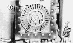
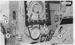
1. Remove bolts (1) from shroud.
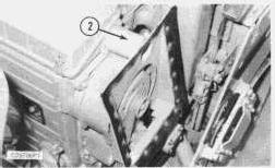
2. Disconnect shroud from tube (2) and remove shroud.
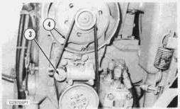
3. Loosen tensioner bolt (3) and compress tensioner cylinder and remove belt (4).
NOTICE
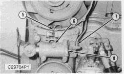
Care must be taken when removing and installing tube (7). The banjo bolt that holds tube (7) in place is hollow, with an oil hole, so it must be tightened into place carefully. Also, the tube must have a seal washer on each side of the tube.
4. Disconnect wire (5) and tube (7). Remove three bolts (6) and remove tensioner (8) with large O -ring seal.
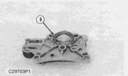
NOTE: At the time of assembly, install o-ring seal (9) on the back side of the tensioner.
NOTE: Install in the reverse order.
Disassemble And Assemble Belt Tensioner
Start By:
a. remove belt tensioner
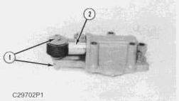
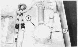
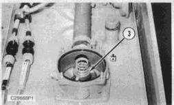
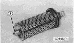
1. Remove bolt (1) and remove belt tensioner cylinder (2).
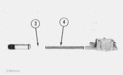
2. Remove plastic slug (3) and spring (4) from tensioner body.
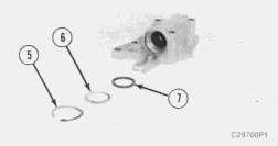
3. Remove snap ring (5), washer (6) and seal (7) from tensioner body.
NOTE: Assemble in the reverse order.
End By:
a. install belt tensioner
1993 - 2025 Caterpillar Inc.
Product: VIBRATORY COMPACTOR
Model: CB-214B VIBRATORY COMPACTOR 6LF
Configuration: CB-214B, CB-224B VIBRATORY COMPACTOR 6LF00001-UP (MACHINE)
Disassembly and Assembly
CB-214B & CB-224B VIBRATORY COMPACTORS VEHICLE SYSTEMS
Media Number -KENR1571-00
Brake Control
SMCS - 4262-010
Publication Date -01/10/1989
Date Updated -10/10/2001
Remove And Install Brake Control
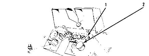
1. Tilt control panel forward for access to brake control (2). Also brake indicator light (1).
NOTE: Install in the reverse order.
Copyright 1993 - 2025 Caterpillar Inc. All Rights Reserved. Private Network For SIS Licensees. Tue Jan 28 10:56:04 UTC+0700 2025
Product: VIBRATORY COMPACTOR
Model: CB-214B VIBRATORY COMPACTOR 6LF
Configuration: CB-214B, CB-224B VIBRATORY COMPACTOR 6LF00001-UP (MACHINE)
Disassembly and Assembly
CB-214B & CB-224B VIBRATORY COMPACTORS VEHICLE SYSTEMS
Media Number -KENR1571-00
Publication Date -01/10/1989
Brake Solenoid Block Valve
SMCS - 4282-017; 4282-010
Date Updated -10/10/2001
Remove and Install Brake Solenoid Block Valve
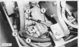
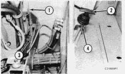
1. Disconnect traction pump control cable (1) and position it out of the way. Disconnect electrical connection (2). Identify and disconnect three hydraulic hoses (3) from the block valve. Remove two capscrews (4) and remove the brake block valve.
NOTE: Install in the reverse order.
Disassemble And Assemble Brake Solenoid Block Valve
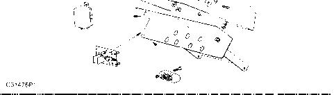
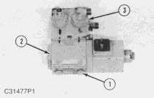
1. Remove four plugs (1) and remove four capscrews. Separate solenoid (2) from block valve (3).
NOTE: assemble in the reverse order. Copyright 1993 - 2025 Caterpillar Inc. All Rights Reserved. Tue Jan 28 10:55:48 UTC+0700 2025
Product: VIBRATORY COMPACTOR
Model: CB-214B VIBRATORY COMPACTOR 6LF
Configuration: CB-214B, CB-224B VIBRATORY COMPACTOR 6LF00001-UP (MACHINE)
Disassembly and Assembly
CB-214B & CB-224B VIBRATORY COMPACTORS VEHICLE SYSTEMS
Media Number -KENR1571-00
Brake
SMCS - 3275-010
Publication Date -01/10/1989
Date Updated -10/10/2001
Remove And Install Brake
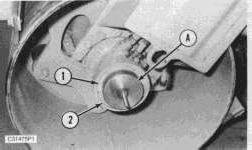
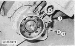
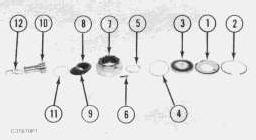
1. Disconnect the oil line from the brake housing and cap off the line. Install tooling (A) and compress brake spring (1), remove snap ring (2) and then remove tooling (A).
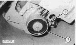
2. Remove brake piston (3) from brake housing (7).
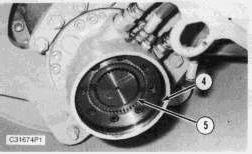
3. Remove o-ring (4) and shim set (5) from brake housing (7).
4. Remove eight bolts (6), brake housing (7), friction discs (8) and brake discs (9).
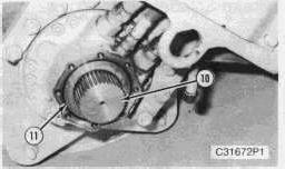
5. Remove o-ring (11) and shaft (10).
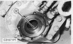
6. Remove shaft seal group (12).
NOTE: Install in the reverse order. Copyright 1993 - 2025 Caterpillar Inc.
Rights Reserved.
Network For SIS Licensees. Tue Jan 28 10:56:25 UTC+0700 2025
Product: VIBRATORY COMPACTOR
Model: CB-214B VIBRATORY COMPACTOR 6LF
Configuration: CB-214B, CB-224B VIBRATORY COMPACTOR 6LF00001-UP (MACHINE)
Disassembly and Assembly
CB-214B & CB-224B VIBRATORY COMPACTORS VEHICLE SYSTEMS
Media Number -KENR1571-00
Publication Date -01/10/1989
Date Updated -10/10/2001
Charge Filter, Vibratory Relief Valve And Solenoid Group
SMCS - 1315-017; 1620-017; 1620; 5479-010
Remove And Install Charge Filter, Vibratory Relief Valve And Solenoid Group
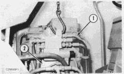
1. Identify and disconnect six hoses from the charge filter, relief valve and solenoid. With hoist in place, remove two bolts (2) and remove charge filter, vibratory relief valve and solenoid.
NOTE: Install in the reverse order.
Disassemble And Assemble Charge Filter
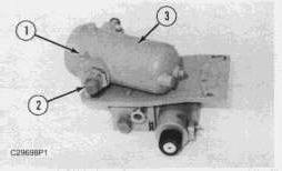
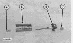
1. Remove two bolts (1), two spacers (2) and remove charge filter (3) from the relief valve and solenoid mounting plate.
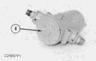
2. Remove cover (4) from the charge filter.
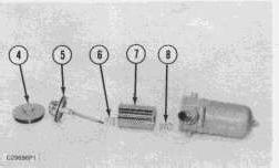
3. Remove element support and seal (5), spring (6), filter element (7) and spring (8) from the filter housing.
NOTE: Assemble in the reverse order.
Disassemble And Assemble Vibratory Relief Valve And Solenoid
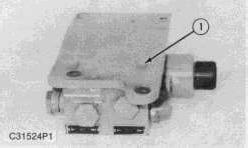
1. Remove bolts (1) and remove the mounting plate from the relief valve and solenoid group.
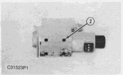
2. Remove four capscrews (2) and remove solenoid group from the relief valve.
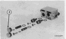
3. Remove plugs (3) and remove springs, poppets, valves and seals from the relief valve body, as illustrated.
NOTE: Assemble in the reverse order.
Copyright 1993 - 2025 Caterpillar Inc. All Rights Reserved. Private Network For SIS Licensees.
Tue Jan 28 10:56:39 UTC+0700 2025
Product: VIBRATORY COMPACTOR
Model: CB-214B VIBRATORY COMPACTOR 6LF
Configuration: CB-214B, CB-224B VIBRATORY COMPACTOR 6LF00001-UP (MACHINE)
Disassembly and Assembly
CB-214B & CB-224B VIBRATORY COMPACTORS VEHICLE SYSTEMS
Media Number -KENR1571-00
Drum Scrapers
SMCS - 6607-010
Publication Date -01/10/1989
Date Updated -10/10/2001
Remove And Install Drum Scrapers
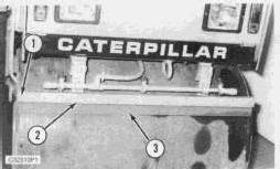
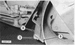
1. Remove six bolts, remove bar (2) and remove scraper (3).
2. Remove six bolts (5), remove bar (4) and scraper (6).
Copyright 1993 - 2025 Caterpillar Inc.
Rights Reserved.
Network For SIS
Tue Jan 28 10:57:24 UTC+0700 2025
Product: VIBRATORY COMPACTOR
Model: CB-214B VIBRATORY COMPACTOR 6LF
Configuration: CB-214B, CB-224B VIBRATORY COMPACTOR 6LF00001-UP (MACHINE)
Disassembly and Assembly
CB-214B & CB-224B VIBRATORY COMPACTORS VEHICLE SYSTEMS
Media Number -KENR1571-00
Publication Date -01/10/1989
Engine Throttle Control
SMCS - 1269-010
Remove And Install Engine Throttle Control
Date Updated -10/10/2001
1. Remove pin (1) to disconnect the throttle linkage clevis from the throttle lever. Loosen nuts (3) and (4) and remove engine throttle control (2).
NOTE: Install in the reverse order.
Copyright 1993 - 2025 Caterpillar Inc. All Rights Reserved. Private Network For SIS Licensees.
Tue Jan 28 10:48:23 UTC+0700 2025
Product: VIBRATORY COMPACTOR
Model: CB-214B VIBRATORY COMPACTOR 6LF
Configuration: CB-214B, CB-224B VIBRATORY COMPACTOR 6LF00001-UP (MACHINE)
Disassembly and Assembly
CB-214B & CB-224B VIBRATORY COMPACTORS VEHICLE SYSTEMS
Media Number -KENR1571-00
Engine
SMCS - 1000-010
Publication Date -01/10/1989
Date Updated -10/10/2001
Remove And Install Engine
Start By:
a. remove charge filter, relief valve and solenoid group
b. remove traction pump
c. remove muffler and exhaust pipe
NOTE: Drain engine oil and disconnect the engine oil drain hose.
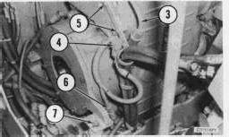
1. Disconnect small line (1) from the engine. Remove three wire clamps (2).
2. Disconnect fuel line (3) at the fuel filter. Disconnect electrical connector (4) and (6). Remove two bolts (5) and remove the hose support bracket from the engine. Remove two engine rear mount nuts (7).
3. Disconnect three hoses (8) from the steering pump. Disconnect throttle (9). Remove two engine front mount nuts (10).
NOTE: Be sure that all engine connections have been disconnected before removing the engine from the machine.
4. Hook a hoist to the center lifting bracket on the engine. Lift the engine 101.6 to 127 mm (4 to 5 in.), for access, and disconnect the engine ground strap and the two wires from the starter motor. Remove the engine from the machine. Weight of the engine is 295 kg (650 lbs.)
NOTE: Install in the reverse order.
NOTE: Connect the engine oil drain hose and fill the engine with the specified oil.
End By:
a. install muffler and exhaust pipe
b. install traction pump
c. install charge filter, relief valve and solenoid group
Product: VIBRATORY COMPACTOR
Model: CB-214B VIBRATORY COMPACTOR 6LF
Configuration: CB-214B, CB-224B VIBRATORY COMPACTOR 6LF00001-UP (MACHINE)
Disassembly and Assembly
CB-214B & CB-224B VIBRATORY COMPACTORS VEHICLE SYSTEMS
Media Number -KENR1571-00
Hydraulic Filter
SMCS - 5720-010
Publication Date -01/10/1989
Date Updated -10/10/2001
Remove And Install Hydraulic Filter
1. Remove four nuts (1) with washers and remove filter cover (2). Remove the filter element assembly.
2. Remove filter assembly (3).
3. Remove nut (4) and spring from filter assembly.
4. Remove element (5) from support bracket (6). Remove spring (7) from the support.
NOTE: Install in the reverse order.
Copyright 1993 - 2025 Caterpillar Inc. All Rights Reserved. Private Network For SIS Licensees.
Tue Jan 28 10:50:31 UTC+0700 2025
Product: VIBRATORY COMPACTOR
Model: CB-214B VIBRATORY COMPACTOR 6LF
Configuration: CB-214B, CB-224B VIBRATORY COMPACTOR 6LF00001-UP (MACHINE)
Disassembly and Assembly
CB-214B & CB-224B VIBRATORY COMPACTORS VEHICLE SYSTEMS
Media Number -KENR1571-00
Hydraulic Tank
SMCS - 5056-010
Publication Date -01/10/1989
Date Updated -10/10/2001
Remove And Install Hydraulic Tank
1. Remove the battery and drain the oil from the hydraulic tank.
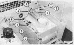
2. Remove sheet metal restraining cable (9) from the tank. Remove harness clamps (6) and (8) from the top of the tank. Disconnect two wires (7). Disconnect wire (2) from horn (3). Loosen clamp (5) on the filter hose. Remove two bolts (1) from manifold (4) and remove horn (3).
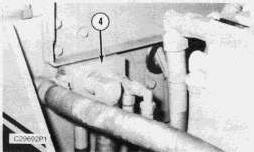
3. Remove manifold (4) from the filter hose and position manifold (4) out of the way.
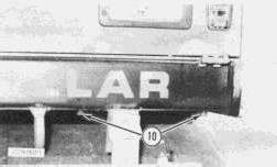
4. Remove two bolts (10) at the front of the tank.
5. remove two bolts (12) at the rear of the tank. Disconnect hose (13) from the tank and remove the tank.
NOTE: Install in the reverse order. Copyright 1993 - 2025 Caterpillar Inc.
Tue Jan 28 10:50:15 UTC+0700 2025
Product: VIBRATORY COMPACTOR
Model: CB-214B VIBRATORY COMPACTOR 6LF
Configuration: CB-214B, CB-224B VIBRATORY COMPACTOR 6LF00001-UP (MACHINE)
Disassembly and Assembly
CB-214B & CB-224B VIBRATORY COMPACTORS VEHICLE SYSTEMS
Media Number -KENR1571-00
Muffler
SMCS - 1062-010
Publication Date -01/10/1989
Date Updated -10/10/2001
Remove And Install Muffler
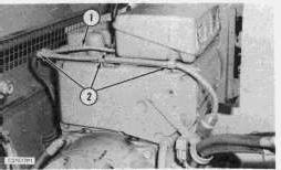
1. Remove two mount bolts from mounting bracket (1).
2. Remove two Allen head bolts (2) and remove muffler (3).
NOTE: Install in the reverse order.
Product: VIBRATORY COMPACTOR
Model: CB-214B VIBRATORY COMPACTOR 6LF
Configuration: CB-214B, CB-224B VIBRATORY COMPACTOR 6LF00001-UP (MACHINE)
Disassembly and Assembly
CB-214B & CB-224B VIBRATORY COMPACTORS VEHICLE SYSTEMS
Media Number -KENR1571-00
Pump Drive Coupling
SMCS - 5062-010
Publication Date -01/10/1989
Date Updated -10/10/2001
Remove And Install Pump Drive Coupling
Start By:
a. remove traction pump
b. remove charge filter, vibratory relief valve and solenoid group
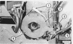
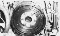
2. Install lifting device (1) and support the rear of the engine. Disconnect traction control cable (5) from rear support plate (4). Remove two mounting nuts (3) from the motor mounts and lift engine enough to clear the mounting studs. Remove six bolts (2) and remove rear support plate (4).
3. Remove bolts (6) from pump drive coupling (7) and remove coupling (7) from the engine flywheel.
NOTE: Install in the reverse order.
a. install traction pump
b. install charge filter, vibratory relief valve and solenoid group
Copyright 1993 - 2025 Caterpillar Inc. All Rights Reserved. Private Network For SIS Licensees.
Tue Jan 28 10:49:26 UTC+0700 2025
Product: VIBRATORY COMPACTOR
Model: CB-214B VIBRATORY COMPACTOR 6LF
Configuration: CB-214B, CB-224B VIBRATORY COMPACTOR 6LF00001-UP (MACHINE)
Disassembly and Assembly
CB-214B & CB-224B VIBRATORY COMPACTORS VEHICLE SYSTEMS
Media Number -KENR1571-00
Starter
SMCS - 1453-010
Publication Date -01/10/1989
Date Updated -10/10/2001
Remove And Install Starter
Start By:
a. remove engine
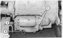
1. Disconnect two wires (3) and remove wire clamp (2). Remove two bolts (1) and remove the starter.
NOTE: Install in the reverse order.
End By:
a. install engine Copyright 1993 - 2025 Caterpillar Inc.
Rights Reserved.
Network For SIS Licensees. Tue Jan 28 10:49:40 UTC+0700 2025