DOWNLOAD LINK
For some reason if link does not work download this pdf and then click
Product: MARINE ENGINE
Model: C7 MARINE ENGINE C7D
Configuration: C7 Marine Engine C7D00001-UP
Operation and Maintenance Manual
C7 Marine Engine
i06103548
Engine Air Cleaner Service Indicator - Inspect - If Equipped
SMCS - 7452-040
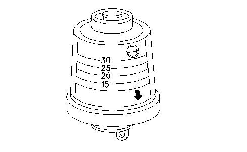
Some engines may be equipped with a different service indicator. Some engines are equipped with a differential gauge for inlet air pressure. The differential gauge for inlet air pressure displays the difference in the pressure that is measured before and after the air cleaner element. As the air cleaner element becomes dirty, the pressure differential rises. If your engine is equipped with a different type of service indicator, follow the OEM recommendations in order to service the air cleaner service indicator.
The service indicator may be mounted on the clean side of the air cleaner housing or in a remote location.
Illustration 1 g00103777 Typical service indicator
Observe the service indicator. The air cleaner element should be cleaned or the air cleaner element should be replaced when one of the following conditions occur:
• The yellow diaphragm enters the red zone.
• The red piston locks in the visible position.
Test the Service Indicator
Service indicators are important instruments.
• Check for ease of resetting. The service indicator should reset in less than three pushes.
• Check the movement of the service indicator core when the engine is run at full load speed. The core should latch approximately at the greatest vacuum that is attained.
If the service indicator does not reset easily, or if the core does not latch at the greatest vacuum, the service indicator should be replaced. If the new service indicator will not reset, the hole for the service indicator may be plugged.
If necessary, replace the service indicator more frequently in environments that are severely dusty. Replace the service indicator annually regardless of the operating conditions. Replace the service indicator when the engine is overhauled, and whenever major engine components are replaced.
Note: When a new service indicator is installed, excessive force may crack the top of the service indicator. Tighten the service indicator to a torque of 2 N·m (18 lb in).
Product: MARINE ENGINE
Model: C7 MARINE ENGINE C7D
Configuration: C7 Marine Engine C7D00001-UP
Operation and Maintenance Manual
C7 Marine Engine
Engine Air Cleaner Element (Single Element)Inspect/Clean/Replace
SMCS - 1051; 1054-040; 1054-070; 1054-510
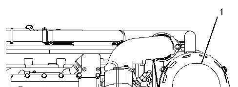
(1) Air cleaner element
Note: Use the 102-9720 Cleaning Kit in order to clean the air cleaner element. These products contain the detergent and oil that is made specifically for the maintenance of the air cleaner elements.
1. Remove the air cleaner element. Tap the air cleaner element in order to dislodge dirt particles. Gently brush the air cleaner element with a soft bristle brush.
NOTICE
Do not use gasoline, steam, caustic or unapproved detergents, or parts cleaning solvents. Do not use high pressure water or air to clean the air cleaner element. Any of those liquids or methods can cause air cleaner element damage.
2. Spray the air cleaner element with the cleaning solution. Allow the air cleaner element to stand for 20 minutes.
3. Rinse the air cleaner element with low water pressure. The maximum water pressure for this procedure is 275 kPa (40 psi). Tap water is acceptable. Start to rinse the air cleaner element from the clean side (inside). Next, clean the dirty side (outside) in order to flush out dirt. Inspect the air cleaner element for tears and/or holes after the air cleaner element is cleaned. Do not reuse a damaged air cleaner elements.
NOTICE
Do not use compressed air, open flame, or hot air to dry the air cleaner element. Excess heat shrinks cotton fiber, and compressed air may blow holes in the material. Allow the air cleaner element to air dry.
4. Shake excess water off the air cleaner element and allow the air cleaner element to air dry. Drying the air cleaner element in the sun speeds the process.
NOTICE
Do not use transmission fluid, engine oil, diesel fuel, or other lubricant to oil the air cleaner element. The air cleaner element can not function correctly if improper oil is used. Never operate an engine with a dry air cleaner element. The air cleaner element can not function correctly without oil. Always saturate the clean air cleaner element with the recommended oil.
5. The dry air cleaner element should be oiled before installation. Apply small amounts of oil across the top of each pleat. Allow the oil wick into the air cleaner element for 20 minutes. Oil any remaining "white" spots.
6. Inspect the housing and the clamp for air cleaner element. Replace the housing and the clamp, if necessary. Install the clean, oiled air cleaner element. Refer to Specifications, SENR3130, "Torque Specifications" for more information on the proper torques.
1993 - 2024 Caterpillar Inc.
Rights Reserved.
Product: MARINE ENGINE
Model: C7 MARINE ENGINE C7D
Configuration: C7 Marine Engine C7D00001-UP
Operation and Maintenance Manual
C7 Marine Engine Media
-01/12/2014
Engine Crankcase Breather - Clean
SMCS - 1317-070
NOTICE
Perform this maintenance with the engine stopped.
If the crankcase breather is not maintained on a regular basis, the crankcase breather will become plugged. A plugged crankcase breather will cause excessive crankcase pressure that may cause crankshaft seal leakage.
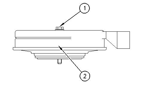
Illustration 1
i02053400
(1) Bolt (2) Breather assembly
1. Loosen the hose clamp and remove the hose from breather assembly (2).
2. Loosen bolt (1). Remove breather assembly (2) and the seal.
3. Wash the breather element in solvent that is clean and nonflammable. Allow the breather element to dry before installation.
4. Install a breather element that is clean and dry. Install breather assembly (2) and the seal. Tighten bolt (1).
5. Install the hose. Install the hose clamp. Refer to Specifications, SENR3130, "Torque Specifications" for the proper torques.
Copyright 1993 - 2024 Caterpillar Inc. All Rights Reserved. Private Network For SIS Licensees.
Fri Oct 18 01:11:38 UTC+0530 2024
Product: MARINE ENGINE
Model: C7 MARINE ENGINE C7D
Configuration: C7 Marine Engine C7D00001-UP
Operation and Maintenance Manual
C7 Marine Engine
Engine - Clean
SMCS - 1000-070
Personal injury or death can result from high voltage.
Moisture can create paths of electrical conductivity.
Make sure that the electrical system is OFF. Lock out the starting controls and tag the controls "DO NOT OPERATE".
NOTICE
Accumulated grease and oil on an engine is a fire hazard. Keep the engine clean. Remove debris and fluid spills whenever a significant quantity accumulates on the engine.
Periodic cleaning of the engine is recommended. Steam cleaning the engine will remove accumulated oil and grease. A clean engine provides the following benefits:
• Easy detection of fluid leaks
• Maximum heat transfer characteristics
• Ease of maintenance
Note: Caution must be used in order to prevent electrical components from being damaged by excessive water when you clean the engine. Avoid electrical components such as the alternator, the starter, and the ECM.
Copyright 1993 - 2024 Caterpillar Inc. All Rights Reserved. Private Network For SIS Licensees.
Fri Oct 18 01:11:35 UTC+0530 2024
Product: MARINE ENGINE
Model: C7 MARINE ENGINE C7D
Configuration: C7 Marine Engine C7D00001-UP
Operation and Maintenance Manual
C7 Marine Engine Media Number -SEBU7897-13
Engine Mounts - Inspect
SMCS - 1152-040
Inspect the engine mounts for deterioration and for proper bolt torque. Engine vibration can be caused by the following conditions:
• Improper mounting of the engine
• Deterioration of the engine mounts
Any engine mount that shows deterioration should be replaced. Refer to Special Publication, SENR3130, "Torque Specifications" for the recommended torques. Refer to the OEM recommendations for more information.
Copyright 1993 - 2024 Caterpillar Inc. All Rights Reserved. Private Network For SIS Licensees. Fri Oct 18 01:11:26 UTC+0530 2024
i02456872
Product: MARINE ENGINE
Model: C7 MARINE ENGINE C7D
Configuration: C7 Marine Engine C7D00001-UP
Operation and Maintenance Manual
C7 Marine Engine Media
Engine Oil Level - Check
SMCS - 1348-535-FLV
-01/12/2014
i06103562
Check the oil level of the engine after the engine has stopped. This maintenance procedure must be performed on a level surface.
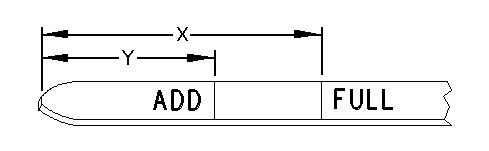
Illustration 1 g00110310 (Y) "ADD" mark (X) "FULL" mark
1. Maintain the oil level between the "ADD" mark (Y) and the "FULL" mark (X) on the oil level gauge. Do not fill the crankcase above "FULL" mark (X).
NOTICE
Operating your engine when the oil level is above the "FULL" mark could cause your crankshaft to dip into the oil. The air bubbles created from the crankshaft dipping into the oil reduces the oil's lubricating characteristics and could result in the loss of power or engine failure.
2. Remove oil filler cap and add oil, if necessary. Clean the oil filler cap. Reinstall the oil filler cap.
Copyright 1993 - 2024 Caterpillar Inc. All Rights Reserved. Private Network For SIS Licensees.
Fri Oct 18 01:11:04 UTC+0530 2024
Product: MARINE ENGINE
Model: C7 MARINE ENGINE C7D
Configuration: C7 Marine Engine C7D00001-UP
Operation and Maintenance Manual
C7 Marine Engine
Crankshaft Vibration Damper - Inspect
SMCS - 1205-040
Damage to the crankshaft vibration damper or failure of the crankshaft vibration damper can increase torsional vibrations. The vibrations can damage the crankshaft and other engine components. A deteriorating damper can cause excessive gear train noise at variable points in the speed range.
The damper is mounted to the crankshaft which is located behind the belt guard on the front of the engine.
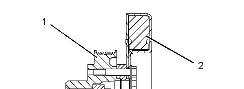
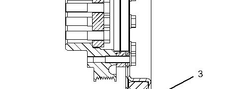
Illustration 1 g01134779
Viscous vibration damper
Typical example
(1) Crankshaft pulley
(2) Weight
(3) Case
Inspection
Inspect the damper for the following conditions:
• The damper is dented, cracked, or fluid is leaking from the damper.
• The paint on the damper is discolored from excessive heat.
• The damper is bent.
• The bolt holes are worn or there is a loose fit for the bolts.
• The engine has had a crankshaft failure due to torsional forces.
• Extreme wear of the gear train.
Replace the damper if any of these conditions exist.
Removal and Installation
Refer to this Operation and Maintenance Manual, "Belts - Inspect/Adjust/Replace" for information on removing and on installing the belt. Refer to the Disassembly and Assembly Manual, "Vibration Damper and Pulley - Remove and Install" for information on removing and installing the damper.
Copyright 1993 - 2024 Caterpillar Inc. All Rights Reserved. Private Network For SIS Licensees. Fri Oct 18 01:10:55 UTC+0530 2024
Product: MARINE ENGINE
Model: C7 MARINE ENGINE C7D
Configuration: C7 Marine Engine C7D00001-UP
Operation and Maintenance Manual
C7 Marine Engine
Engine Oil Level Gauge - Calibrate
SMCS - 1326-524
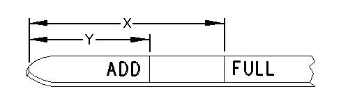
The engine is shipped with an engine oil level gauge that is not marked. The engine oil level gauge is not marked because the angle of installation can be different for each engine. The angle of installation will affect the "ADD" mark (Y) and the "FULL" mark (X) that is engraved on the engine oil level gauge.
The engine oil level gauge must be calibrated after the engine is installed in the vessel. Table 1 lists the corresponding "ADD" mark, "FULL" mark and the angle of installation. Use a marking pen in order to engrave "ADD" mark (Y) and "FULL" mark (X) on the engine oil level gauge according to the information in Table 1.
Illustration 1 g00110310
Oil Level Gauge
(Y) "ADD" mark (X) "FULL" mark
Calibration of Oil Level Gauge
Table 1
Engine Oil Level Gauge
i01094856
Angle(1) "FULL" Mark (X) "ADD" Mark (Y)
10 degrees 125 mm (4.92 inch) 114 mm (4.49 inch)
9 degrees 124 mm (4.89 inch) 106 mm (4.17 inch)
8 degrees 122 mm (4.80 inch) 102 mm (4.02 inch)
7 degrees 120 mm (4.72 inch) 96 mm (3.78 inch)
6 degrees 115 mm (4.53 inch) 89 mm (3.50 inch)
5 degrees 110 mm (4.33 inch) 81 mm (3.19 inch)
4 degrees 101 mm (3.98 inch) 71 mm (2.80 inch)
3 degrees 94 mm (3.70 inch) 66 mm (2.60 inch)
2 degrees 90 mm (3.54 inch) 59 mm (2.32 inch)
1 degree 82 mm (3.23 inch) 52 mm (2.05 inch)
0 degrees 76 mm (2.99 inch) 46 mm (1.81 inch)
-1 degree 65 mm (2.56 inch) 39 mm (1.54 inch)
-2 degrees 59 mm (2.32 inch) 33 mm (1.30 inch)
-3 degrees 53 mm (2.09 inch) 26 mm (1.02 inch)
-4 degrees 46 mm (1.81 inch) 20 mm (0.79 inch)
-5 degrees 39 mm (1.54 inch) 12 mm (0.47 inch)
(1) The angle indicates the number of degrees that the front of the engine is raised. A negative angle indicates the number of degrees that the front of the engine is lowered.
Verifying the Calibration of the Oil Level Gauge
Caterpillar recommends verifying the calibration of the oil level gauge at the first oil change. Use the following procedure to verify the "FULL" mark on the oil level gauge:
Note: The vessel must be level in order to perform this procedure.
1. Operate the engine until normal operating temperature is achieved. Stop the engine. Remove one of the drain plugs for the engine crankcase. Allow the engine oil to drain.
2. Remove the used engine oil filter. Install the new engine oil filter. Install the crankcase drain plug and tighten the crankcase drain plug.
3. Add 25 L (26.5 qt) of the recommended oil grade and weight of engine oil to the crankcase.
Note: The engine may be equipped with auxiliary engine oil filters which require additional oil. Refer to the OEM specifications.
To help prevent crankshaft or bearing damage, crank engine to fill all filters before starting. Do not crank engine for more than 30 seconds.
NOTICE
Do not crank the engine for more than 30 seconds. Allow the starting motor to cool for two minutes before cranking again.
Turbocharger (if equipped) damage can result, if the engine rpm is not kept low until the engine oil light/gauge verifies the oil pressure is sufficient.
4. Start the engine. Ensure that the lubrication system and the new engine oil filter is filled. Inspect the lubrication system for leaks.
5. Stop the engine and allow the engine oil to drain into the engine crankcase for approximately ten minutes.
6. Check the engine oil level. If necessary, use a marking pen in order to correct the "FULL" mark (X).
Oct 18 01:10:51 UTC+0530 2024
Product: MARINE ENGINE
Model: C7 MARINE ENGINE C7D
Configuration: C7 Marine Engine C7D00001-UP
Operation and Maintenance Manual
C7 Marine Engine
Cooling System Supplemental Coolant Additive (SCA) -
Test/Add
SMCS - 1352-045; 1395-081
Note: This maintenance is NOT required for cooling systems that are filled with Extended Life Coolant.
Cooling system coolant additive contains alkali. To help prevent personal injury, avoid contact with the skin and eyes. Do not drink cooling system coolant additive.
NOTICE
Excessive supplemental coolant additive concentration can form deposits on the higher temperature surfaces of the cooling system, reducing the engine's heat transfer characteristics. Reduced heat transfer could cause cracking of the cylinder head and other high temperature components.
Excessive supplemental coolant additive concentration could also result in blockage of the heat exchanger, overheating, and/or accelerated wear of the water pump seal.
Do not exceed the recommended amount of supplemental coolant additive concentration.
NOTICE
Care must be taken to ensure that fluids are contained during performance of inspection, maintenance, testing, adjusting, and repair of the product. Be prepared to collect the fluid with suitable containers before opening any compartment or disassembling any component containing fluids.
Refer to Special Publication, NENG2500, "Caterpillar Dealer Service Tool Catalog" and to Special Publication, GECJ0003, "Cat Shop Supplies and Tools" for tools and supplies suitable to collect and contain fluids on Caterpillar products.
Dispose of all fluids according to applicable regulations and mandates.
Note: Caterpillar recommends an S·O·S coolant analysis (Level 1).
Cooling Systems that Use Conventional Coolant
Test the Concentration of the SCA
NOTICE
Do not exceed the recommended six percent supplemental coolant additive concentration.
Test the concentration of the SCA with the 4C-9301 Coolant Conditioner Test Kit.
Add the SCA, If Necessary
Pressurized System: Hot coolant can cause serious burns. To open the cooling system filler cap, stop the engine and wait until the cooling
system components are cool. Loosen the cooling system pressure cap slowly in order to relieve the pressure.
1. Remove the cooling system filler cap slowly.
2. If necessary, drain some coolant in order to allow space for the addition of the SCA.
3. Add the proper amount of SCA. For the proper amount of SCA, refer to this Operation and Maintenance Manual, "Refill Capacities and Recommendations" or refer to this Operation and Maintenance Manual, "Fluid Recommendations". The proper concentration of SCA depends on the type of coolant that is used. For the proper concentration of SCA, refer to Special Publication, SEBU6251, "Caterpillar Commercial Diesel Engine Fluids Recommendations".
4. Clean the cooling system filler cap. Install the cooling system filler cap.
Copyright 1993 - 2024 Caterpillar Inc.
Rights Reserved.
Network For SIS Licensees.
Product: MARINE ENGINE
Model: C7 MARINE ENGINE C7D
Configuration: C7 Marine Engine C7D00001-UP
Operation and Maintenance Manual
C7 Marine Engine
Engine Oil Sample - Obtain
SMCS - 1348-554-SM
In addition to a good preventive maintenance program, Caterpillar recommends using S·O·S oil analysis at regularly scheduled intervals. S·O·S oil analysis provides infrared analysis, which is required for determining nitration and oxidation levels.
Obtain the Sample and the Analysis
Hot oil and hot components can cause personal injury. Do not allow hot oil or hot components to contact the skin.
Before you take the oil sample, complete the Label, PEEP5031 for identification of the sample. To help obtain the most accurate analysis, provide the following information:
• Engine model
• Service hours on the engine
• The number of hours that have accumulated since the last oil change
• The amount of oil that has been added since the last oil change
To ensure that the sample is representative of the oil in the crankcase, obtain a warm, mixed oil sample.
To avoid contamination of the oil samples, the tools and the supplies that are used for obtaining oil samples must be clean.
i08234825