
C7.1 MARINE ENGINE

Note: Use Bookmarks panel to navigate
DOWNLOAD LINK
For some reason if link does not work download this pdf and then click

Product: MARINE ENGINE
Model: C7.1 MARINE ENGINE JEZ
Configuration: C7.1 Marine Propulsion Engine JEZ00001-UP
Disassembly and Assembly
C7.1 Marine Engine
i06744658
Alternator - Remove and Install
SMCS - 1405-010
Removal Procedure
Start By:
a. Remove the alternator belt
1. Turn the battery disconnect switch to the OFF position.
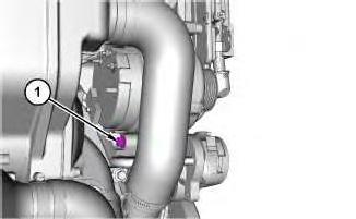
Illustration 1 g06101628
2. Remove bolt (1).
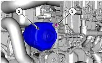
Illustration 2
3. Loosen bolt (3) and slide out towards the electronic control module.
4. Remove alternator (2).
Installation Procedure
1. Install alternator (2) in the reverse order of removal.
Copyright 1993 - 2024 Caterpillar Inc. All Rights Reserved. Private Network For SIS Licensees.
Wed Nov 6 13:40:27 UTC+0530 2024
Product: MARINE ENGINE
Model: C7.1 MARINE ENGINE JEZ
Configuration: C7.1 Marine Propulsion Engine JEZ00001-UP
Disassembly and Assembly
C7.1 Marine Engine
Bearing Clearance - Check
SMCS - 1203-535; 1219-535
Measurement Procedure
Table 1 Required Tools
Tool
198-9142
Plastic Gauge (Green)
0.025 to 0.076 mm (0.001 to 0.003 inch)
Plastic Gauge (Red)
198-9143
198-9144
198-9145
to 0.152 mm (0.002 to 0.006 inch)
Plastic Gauge (Blue)
to 0.229 mm (0.004 to 0.009 inch)
Plastic Gauge (Yellow) 0.230 to 0.510 mm
(0.009 to 0.020 inch)
Note: Plastic gauge may not be necessary when the engine is in the chassis. NOTICE
i05977048
Keep all parts clean from contaminants.
Contaminants may cause rapid wear and shortened component life.
Note: Cat does not recommend the checking of the actual bearing clearances particularly on small engines. This is because of the possibility of obtaining inaccurate results and the possibility of damaging the bearing or the journal surfaces. Each Cat engine bearing is quality checked for specific wall thickness.
Note: The measurements should be within specifications and the correct bearings should be used. If the crankshaft journals and the bores for the block and the rods were measured during disassembly, no further checks are necessary. However, if the technician still wants to measure the bearing clearances, Tooling (A) is an acceptable method. Tooling (A) is less accurate on journals with small diameters if clearances are less than 0.10 mm (0.004 inch).
NOTICE
Lead wire, shim stock or a dial bore gauge can damage the bearing surfaces.
The technician must be very careful to use Tooling (A) correctly. The following points must be remembered:
• Ensure that the backs of the bearings and the bores are clean and dry.
• Ensure that the bearing locking tabs are properly seated in the tab grooves.
• The crankshaft must be free of oil at the contact points of Tooling (A).
1. Put a piece of Tooling (A) on the crown of the bearing that is in the cap.
Note: Do not allow Tooling (A) to extend over the edge of the bearing.
2. Use the correct torque-turn specifications in order to install the bearing cap. Do not use an impact wrench. Be careful not to dislodge the bearing when the cap is installed.
Note: Do not turn the crankshaft when Tooling (A) is installed.
3. Carefully remove the cap, but do not remove Tooling (A). Measure the width of Tooling (A) while Tooling (A) is in the bearing cap or on the crankshaft journal. Refer to Illustration 1.
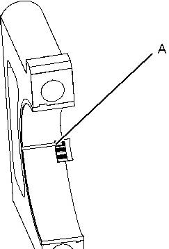

Illustration 1 g01152855
Typical Example
4. Remove all of Tooling (A) before you install the bearing cap.
Note: When Tooling (A) is used, the readings can sometimes be unclear. For example, all parts of Tooling (A) are not the same width. Measure the major width in order to ensure that the parts are within the specification range. Refer to Specifications Manual, "Connecting Rod Bearing Journal" and Specifications Manual, "Main Bearing Journal" for the correct clearances.
Copyright 1993 - 2024 Caterpillar Inc. All Rights Reserved. Private Network For SIS Licensees.
Wed Nov 6 13:42:33 UTC+0530 2024
Product: MARINE ENGINE
Model: C7.1 MARINE ENGINE JEZ
Configuration: C7.1 Marine Propulsion Engine JEZ00001-UP
Disassembly and Assembly
C7.1 Marine Engine
i06753845
Boost Pressure Sensor - Remove and Install
SMCS - 1917-010
Removal Procedure
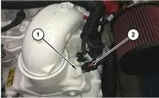
Illustration 1
g06106763
1. Disconnect harness assembly (2) and remove boost pressure sensor (1).
Installation Procedure
1. Install boost pressure sensor (1) in the reverse order of removal.
a. Tighten boost pressure sensor (1) to a torque of 16 ± 3 N·m (142 ± 26 lb in). Wed Nov 6 13:41:03 UTC+0530 2024
Product: MARINE ENGINE
Model: C7.1 MARINE ENGINE JEZ
Configuration: C7.1 Marine Propulsion Engine JEZ00001-UP
Disassembly and Assembly
C7.1 Marine Engine
i06725481
Coolant Level Sensor - Remove and Install
SMCS - 7470
Removal Procedure
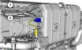
Illustration 1
g06092766
1. Disconnect harness assembly (2) and remove coolant level sensor (1).
Installation Procedure
1. Install coolant level sensor (1) in the reverse order of removal.
a. Tighten coolant level sensor (1) to a torque of 22 ± 3 N·m (195 ± 27 lb in).
Wed Nov 6 13:42:20 UTC+0530 2024
Product: MARINE ENGINE
Model: C7.1 MARINE ENGINE JEZ
Configuration: C7.1 Marine Propulsion Engine JEZ00001-UP
Disassembly and Assembly
C7.1 Marine Engine
i06740365
Coolant Temperature Sensor - Remove and Install
SMCS - 1906-010
Removal Procedure
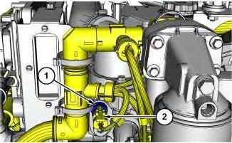
Illustration 1
g06100467
1. Disconnect harness assembly (2) and remove coolant temperature sensor (1).
Installation Procedure
1. Install coolant temperature sensor (1) in the reverse order of removal.
a. Tighten coolant temperature sensor (1) to a torque of 20 ± 3 N·m (177 ± 27 lb in).
Wed Nov 6 13:42:04 UTC+0530 2024
Product: MARINE ENGINE
Model: C7.1 MARINE ENGINE JEZ
Configuration: C7.1 Marine Propulsion Engine JEZ00001-UP
Disassembly and Assembly
C7.1 Marine Engine
Crankshaft - Install
SMCS - 1202-012
Installation Procedure
Table 1 Required Tools
NOTICE
Keep all parts clean from contaminants.
Contaminants may cause rapid wear and shortened component life.
1. Clean the crankshaft and inspect the crankshaft for wear and damage. Refer to Specifications, "Crankshaft" for more information. If necessary, replace the crankshaft or recondition the crankshaft.
2. If necessary, install the crankshaft gear. Refer to Disassembly and Assembly, "Crankshaft Gear - Remove and Install" for the correct procedure.
3. If necessary, install a new crankshaft timing ring. Refer to Disassembly and Assembly, "Crankshaft Timing Ring - Remove and Install" for the correct procedure.
4. Ensure that parent bores for bearing shells in the cylinder block are clean. Ensure that the threads for the main bearing bolts in the cylinder block are clean and free from damage.
5. Clean the main bearing shells and the thrust washers. Inspect the main bearing shells and the thrust washers for wear and damage. If necessary, replace the main bearing shells and the thrust washers.
Note: If the main bearing shells are replaced, check whether oversize main bearing shells were previously installed. If the thrust washers are replaced, check whether oversize thrust washers were previously installed.
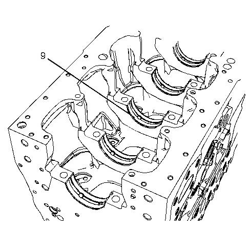
1 g02212656
6. Install upper main bearing shells (9) to the cylinder block. Ensure that the locating tabs for the upper main bearing shells are seated in the slots in the cylinder block.
Illustration
Note: The upper main bearing shells have a groove and two oil holes.
7. Lubricate upper main bearing shells (9) with clean engine oil.
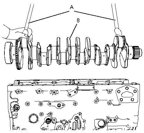
Illustration 2
g02212655
8. Attach Tooling (A) and a suitable lifting device to crankshaft (8). Lift crankshaft (8) into the cylinder block. The weight of the crankshaft is approximately 61 kg (134 lb).
Note: Do not damage any of the finished surfaces on the crankshaft. Do not damage the main bearing shells.
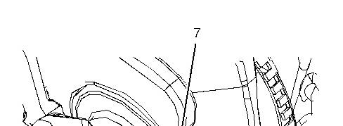
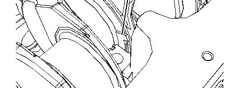

Illustration 3 g02212693
9. Lubricate thrust washers (7) with clean engine oil. Install thrust washers (7) into number six main bearing in the cylinder block.
Note: The grooves in the thrust washers must be located against the crankshaft. The thrust washers have a locating tab at one end. Ensure that the locating tabs are correctly seated in the cylinder block.
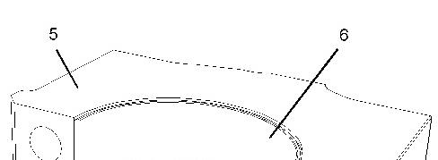
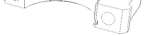
Illustration 4 g02212654
10. Install lower main bearing shells (6) into main bearing caps (5). Ensure that the locating tabs for the lower main bearing shells are correctly seated into the slots in the bearing caps.
Note: The lower main bearing shells are plain bearings that do not have oil holes.
11. Lubricate lower main bearing shells (6) and lubricate the journals of the crankshaft with clean engine oil. Install main bearing caps (5) to the cylinder block.
Note: Ensure the correct location and orientation of main bearing caps (5). The locating tabs for the upper and the lower main bearing shells should be on the same side of the engine.
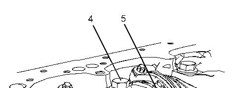
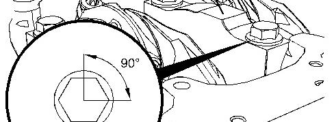

Illustration 5 g02214093
12. Lubricate the threads of bolts (4) with clean engine oil. Lubricate the underside of the heads of bolts (4) with clean engine oil.
13. Install bolts (4) to main bearing caps (5). Evenly tighten the bolts in order to pull the caps into position. Ensure that the caps are correctly seated.
Note: Do not tap the main bearing caps into position as the bearing shells may be dislodged.
14. Tighten bolts (4) to a torque of 80 N·m (59 lb ft).
Turn bolts (4) through an additional 90 degrees. Use Tooling (B) to achieve the final torque.
15. Rotate the crankshaft in order to ensure that there is no binding.
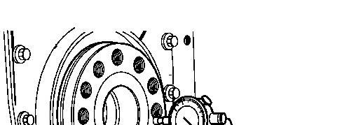
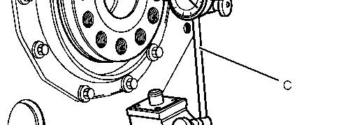

Illustration 6 g01399694
16. Check the crankshaft end play. Push the crankshaft toward the front of the engine. Install Tooling (C) to the cylinder block and the rear face of the crankshaft. Push the crankshaft toward the rear of the engine. Use Tooling (C) to measure the crankshaft end play. The permissible crankshaft end play is 0.10 mm (0.004 inch) to 0.41 mm (0.016 inch).
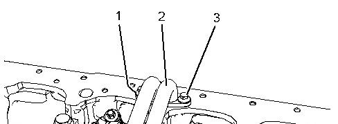
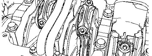

Illustration 7 g02204377
17. Position new gaskets (1) (not shown) onto cylinder block.
18. Position tube assembly (2) onto the cylinder block.
19. Install bolts (3) to tube assembly (2).
20. Tighten bolts (3) to a torque of 22 N·m (195 lb in).
21. If the crankshaft has not been replaced or the crankshaft has not been reconditioned, install the connecting rod bearings. Refer to Disassembly and Assembly, "Connecting Rod BearingsInstall" for the correct procedure.
End By:
a. If necessary, install the pistons and connecting rods. Refer to Disassembly and Assembly, "Pistons and Connecting Rods - Install" for the correct procedure.
b. If necessary, install the cylinder head. Refer to Disassembly and Assembly, "Cylinder headInstall" for the correct procedure.
c. Install the crankshaft rear seal. Refer to Disassembly and Assembly, "Crankshaft Rear SealInstall" for the correct procedure.
d. Install the front housing. Refer to Disassembly and Assembly, "Housing (Front) - Install" for the correct procedure.
e. Install the engine oil pump. Refer to Disassembly and Assembly, "Engine Oil Pump - Install" for the correct procedure. Copyright 1993 - 2024 Caterpillar Inc.
Wed Nov 6 13:44:08 UTC+0530 2024
Product: MARINE ENGINE
Model: C7.1 MARINE ENGINE JEZ
Configuration: C7.1 Marine Propulsion Engine JEZ00001-UP
Disassembly and Assembly
C7.1 Marine Engine
i05018958
Crankshaft - Remove
SMCS - 1202-011
Removal Procedure
Table 1
Required Tools
Tool Part Number Part Description Qty
A 1U-8221 Lifting Sling 2
Start By:
a. Remove the engine oil pump. Refer to Disassembly and Assembly, "Engine Oil PumpRemove" for the correct procedure.
b. Remove the front housing. Refer to Disassembly and Assembly, "Housing (Front) - Remove" for the correct procedure.
c. Remove the crankshaft rear seal. Refer to Disassembly and Assembly, "Crankshaft Rear SealRemove" for the correct procedure.
d. If necessary, remove the cylinder head. Refer to Disassembly and Assembly, "Cylinder HeadRemove" for the correct procedure.
e. If necessary, remove the pistons and connecting rods. Refer to Disassembly and Assembly, "Pistons and Connecting Rods - Remove" for the correct procedure.
Keep all parts clean from contaminants.
Contaminants may cause rapid wear and shortened component life.
1. The engine should be mounted on a suitable stand and placed in the inverted position.
2. If the cylinder head, the pistons and the connecting rods have not been removed already, remove the connecting rod bearings. Refer to Disassembly and Assembly, "Connecting Rod Bearings - Remove" for the correct procedure.
3. Ensure that the main bearing caps are marked for the location and orientation.
1 g02204377
4. Remove bolts (3) from tube assembly (2).
5. Remove tube assembly (2) from the cylinder block.
6. Remove gaskets (1) (not shown).
Illustration
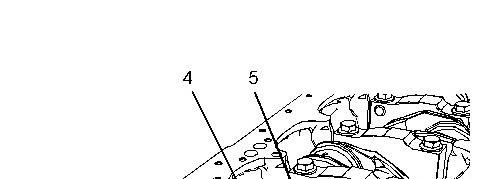
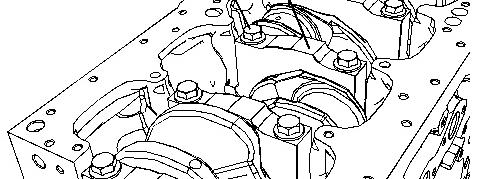

Illustration 2 g02212653
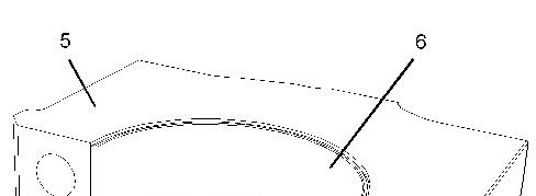
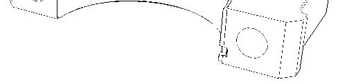
Illustration 3 g02212654
7. Remove bolts (4) and main bearing caps (5) from the cylinder block.
8. Remove lower main bearing shells (6) from main bearing caps (5). Keep the lower main bearing shells with the respective main bearing caps.
Note: The lower main bearing shells are plain bearings that have no oil holes.
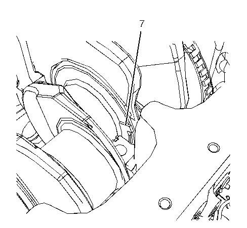
Illustration 4 g02212693
9. For number six main bearing, remove two thrust washers (7) from the cylinder block. In order to remove thrust washers (7), rotate the crankshaft in the correct direction. If necessary, push the crankshaft toward the front of the engine while you rotate the crankshaft, in order to aid removal. If necessary, push the crankshaft toward the rear of the engine while you rotate the crankshaft, in order to aid removal.
Note: The thrust washers have a locating tab at one end.
DOWNLOAD LINK
For some reason if link does not work download this pdf and then click