

This is the sample of the manual click on the download link for complete manual
DOWNLOAD LINK
For some reason if link does not work download this pdf and then click

Product: INDUSTRIAL ENGINE
Model: C3.4 INDUSTRIAL ENGINE CF9
Configuration: XQ60 Power Module CF900001-UP POWERED BY C3.4B Engine
Disassembly and Assembly
C3.4B Generator Set Engines
Media Number -M0121714-00
Date -01/06/2015
Accessory Drive - Remove and Install
SMCS - 1207-010
Removal Procedure
Updated -29/07/2020
NOTICE
Keep all parts clean from contaminants.
Contaminants may cause rapid wear and shortened component life.
NOTICE
Care must be taken to ensure that fluids are contained during performance of inspection, maintenance, testing, adjusting and repair of the product. Be prepared to collect the fluid with suitable containers before opening any compartment or disassembling any component containing fluids.
Dispose of all fluids according to local regulations and mandates.

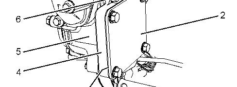

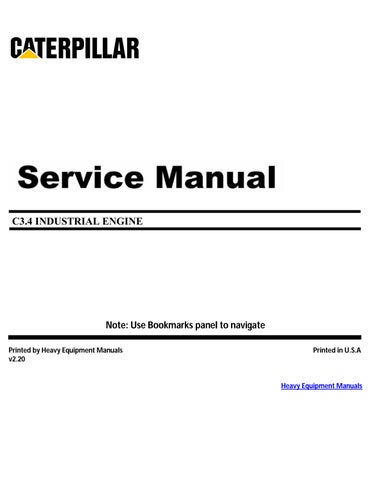
Illustration 1 g02898881
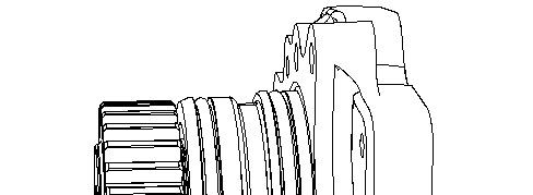
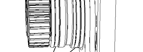

Illustration 2 g02898938
1. If necessary, remove the Original Equipment Manufacturer's (OEM) driven equipment from accessory drive (4). Refer to the OEM for the correct procedure.
2. If the OEM driven equipment was not installed onto accessory drive (4). Remove cover plate (2) and remove gasket (3) (not shown).
3. Remove Allen head bolts (6) from accessory drive (4). Remove the accessory drive housing from the front housing.
4. Remove O-ring seals (7) from the accessory drive.
Installation Procedure
1
Keep all parts clean from contaminants.
Contaminants may cause rapid wear and shortened component life.
1. Inspect the bore in the front housing for damage. If necessary, replace the front housing. Refer to Disassembly and Assembly, "Housing (Front) - Remove" and Disassembly and Assembly, "Housing (Front) - Install" for the correct procedure.
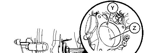


Illustration 3 g06502820
Typical example
2. Ensure that plug (Z) is not fitted in Position (Y) prior to installing accessory drive (4).
Illustration 4 g02898938
3. If accessory drive (7) was removed but will not be installed, the oil gallery in Position (Y) must be plugged using plug (Z). Follow Step 3a through Step 3c to maintain engine oil circulation.
a. Apply Tooling (B) to plug (Z).
b. Install plug (Z) into the front housing.
c. Tighten plug (Z) to a torque of 15 N·m (133 lb in).
4. Install new O-ring seals (7) onto accessory drive (4).
5. Apply Tooling (A) onto O-ring seals (7).
6. Install accessory drive (4) to housing (5).
7. Apply Tooling (B) onto the threads of Allen head bolts (6).
8. Install Allen head bolts (6) to accessory drive (4).
9. Equally tighten the Allen head bolts (6) to pull accessory drive (4) into housing (5).
10. Tighten Allen head bolts to a torque of 25 N·m (221 lb in).
11. Ensure that there is tactile backlash between the idler gear and the accessory drive gear.
12. If necessary, install the OEM driven equipment to accessory drive (4). Refer to the OEM for the correct procedure.
13. If the OEM driven equipment was not installed onto accessory drive (4), position new gasket (3) (not shown) and cover plate (2) onto accessory drive (4).
14. Apply Tooling (B) onto the threads of bolts (1).
15. Install bolts (1) to cover plate (2). Tighten the bolts to a torque of 25 N·m (221 lb in).

Product: INDUSTRIAL ENGINE
Model: C3.4 INDUSTRIAL ENGINE CF9
Configuration: XQ60 Power Module CF900001-UP POWERED BY C3.4B Engine
Disassembly and Assembly
C3.4B Generator Set Engines
i05825517
Alternator - Install
SMCS - 1405-012
Installation Procedure
1. Ensure that all components are clean and free from wear and damage. If necessary, replace any components that are worn or damaged.
2. If necessary, follow Step 2.a through Step 2.g in order to install alternator bracket (4) and tensioner (11) onto the cylinder block.
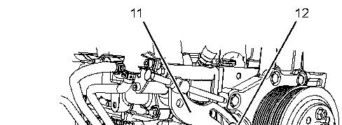
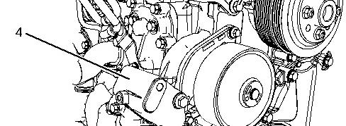

Illustration 1 g03826959
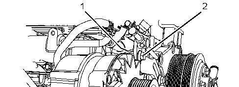
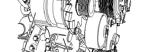

Illustration 2 g02673920
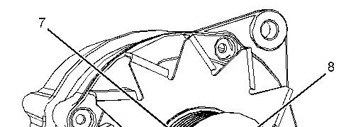
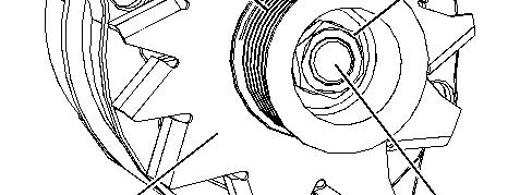
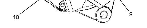
Illustration 3 g02815777
a. Position bracket (4) onto the cylinder block.
b. Install bolts (13) to bracket (4) finger tight.
c. If necessary, install bolt (14) to the coolant tube assembly.
d. Tighten bolts (13) to a torque of 50 N·m (37 lb ft).
e. Tighten bolts (14) to a torque of 25 N·m (221 lb in).
f. Position tensioner (11) onto the fan drive assembly.
g. Install bolt (12) to tensioner (11) finger tight.
3. If necessary, follow Step 3.a through Step 3.f in order to install pulley (8) to alternator (2).
Note: Either of Tooling (A) may be required in order to carry out the installation of the alternator pulley.
a. Place alternator (6) in a suitable support.
b. Ensure that fan (10) is correctly oriented.
c. Install fan (10) to shaft (9).
d. Ensure that pulley (7) is correctly oriented.
e. Install pulley (7) and a new nut (8) to alternator shaft (9).
f. Position a cranked ring spanner onto nut (9). Use a suitable tool in order to turn the shaft of the alternator in a counterclockwise direction. Tighten the nut to the correct torque. Refer to Specifications, "Alternator" for the correct torque.
4. Position the alternator onto bracket (4) and tensioner (11).
5. Install bolt (5) (not shown) and nut (3) finger tight.
6. Install bolt (2) and nut (1) (not shown) finger tight.
7. Install a new alternator belt. Refer to Disassembly and Assembly , "Alternator Belt - Remove and Install" for the correct procedure.
8. Tighten the nut and bolt (2) to a torque of 50 N·m (37 lb ft).
9. Tighten nut and bolt (5) to a torque of 50 N·m (37 lb ft).
10. Connect the wiring harness assembly to the alternator. Refer to Specifications, "Alternator" for the correct torque.
11. Turn the battery disconnect switch to the ON position.
Feb 24 22:33:30 UTC+0530 2024
Product: INDUSTRIAL ENGINE
Model: C3.4 INDUSTRIAL ENGINE CF9
Configuration: XQ60 Power Module CF900001-UP POWERED BY C3.4B Engine
Disassembly and Assembly
C3.4B Generator Set Engines
i05825515
Alternator - Remove
SMCS - 1405-011
Removal Procedure
Start By:
a. Remove the alternator belt. Refer to Disassembly and Assembly, "Alternator Belt - Remove and Install" for the correct procedure.
1. Turn the battery disconnect switch to the OFF position.
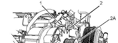
Illustration 1 g03825459
Illustration 2 g02815777
2. Make temporary marks on the alternator harness in order to identify the locations for the connections during the assembly procedure.
3. Disconnect the harness assembly from alternator (6).
4. Support the weight of the alternator and remove bolt (2A).
5. If necessary, support the weight of the alternator and remove nut (1) and bolt (2).
6. Remove nut (3) and bolt (5) (not shown) from alternator (6).
7. Remove alternator (6) from alternator bracket (4).
8. If necessary, follow Step 8.a through Step 8.e in order to remove pulley (7) from alternator (6).
Note: Either of Tooling (A) may be required in order to carry out the removal of the alternator pulley.
a. Place the alternator in a suitable support.
b. Hold shaft (9) of alternator (6) with a suitable tool. Use a cranked ring spanner to loosen nut (8).
c. Make a temporary mark on pulley (7) in order to show the correct orientation.
d. Remove nut (8) and pulley (7) from shaft (9).
e. Remove fan (10) from shaft (9).
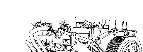


Illustration 3 g03826953
9. If necessary, follow Step 9.a through Step 9.b in order to remove alternator bracket (15) from the cylinder block.
a. If necessary, remove bolt (14) (not shown) from the coolant tube assembly.
b. Remove bolts (13) from alternator bracket (4). Remove the alternator bracket from the cylinder block.
Note: Support the weight of the alternator bracket as the bolts are removed.
Copyright 1993 - 2024 Caterpillar Inc.
Sat Feb 24 22:34:38 UTC+0530 2024
Product: INDUSTRIAL ENGINE
Model: C3.4 INDUSTRIAL ENGINE CF9
Configuration: XQ60 Power Module CF900001-UP POWERED BY C3.4B Engine
Disassembly and Assembly
C3.4B Generator Set Engines Media Number -M0121714-00
i05825510
Alternator Belt - Remove and Install
SMCS - 1357-010
Removal Procedure
1. If the engine has guards, remove the guards. Refer to the Original Equipment Manufacture (OEM) for the correct procedure.
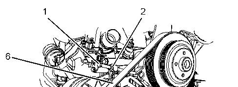
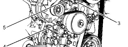

Illustration 1 g02553437
Typical example
2. Loosen locking nut (2) and alternator tensioning bolt (1).
3. Loosen nut and bolt (4).
4. Loosen bolt (3) for adjusting bracket (5).
5. Remove alternator belt (6). Discard the alternator bolt.
Note: Note the routing of the alternator belt before removal.
Installation Procedure
Illustration 2 g02553437
Typical example
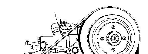
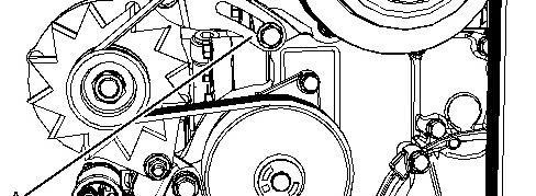

Illustration 3 g02553697
1. Ensure that all components of the pulleys and guide rollers are clean and free from wear and damage. If necessary, replace any components that are worn or damaged.
2. Ensure that the pulleys and guide rollers are free from dirt and build up from the old belt.
3. Install new alternator belt (6) onto pulleys. Ensure that the alternator belt is centered on all pulleys.
Note: The ribs on the alternator belt must be located into the grooves of all pulleys.
4. Tighten bolt (1) until adjusting bracket (5) has reached the full extent of the available adjustment in Position (A).
5. Tighten bolt (3) to a torque of 50 N·m (37 lb ft).
6. Tighten nut and bolt (4) to a torque of 50 N·m (37 lb ft)
7. Rotate tensioning bolt (1) two complete revolutions in a counterclockwise direction. Tighten locking nut (2) to a torque of 30 N·m (266 lb in).
8. If the engine has guards, install the guards. Refer to the OEM for the correct procedure.
Product: INDUSTRIAL ENGINE
Model: C3.4 INDUSTRIAL ENGINE CF9
Configuration: XQ60 Power Module CF900001-UP POWERED BY C3.4B Engine
Disassembly and Assembly
C3.4B Generator Set Engines
Media Number -M0121714-00
Balancer - Install
SMCS - 1220-012
Installation Procedure
Table 1
Required Tools
Keep all parts clean from contaminants.
Contaminants may cause rapid wear and shortened component life.
1. Check all components for wear and damage. If necessary, replace any components that are worn or damaged.
2. Check that the balancer drive gear is not worn or damaged. If necessary, replace the balancer drive gear.
This is the sample of the manual click on the download link for complete manual
DOWNLOAD LINK
For some reason if link does not work download this pdf and then click