
C12.9 MARINE ENGINE

This is the sample of the manual click on the download link for complete manual
DOWNLOAD LINK
For some reason if link does not work download this pdf and then click

Product: MARINE ENGINE
Model: C12.9 MARINE ENGINE TPJ
Configuration: C12.9 Marine Engine TPJ00001-UP
Disassembly and Assembly
C12.9 Marine Engines
Electric Starting Motor - Remove and Install
SMCS - 1453-010
Accidental machine starting can cause injury or death to personnel working on the machine.
To avoid accidental machine starting, turn the battery disconnect switch to the OFF position and remove the key. If the machine is not equipped with a battery disconnect switch, disconnect the battery cables from the battery and tape the battery clamps.
Place a do not operate tag at the battery disconnect switch location to inform personnel that the machine is being worked on.
Removal Procedure
i06603728
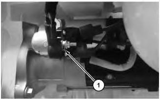
Illustration 1
1. Disconnect cable assembly (1).
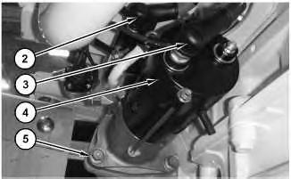
Illustration 2
2. Disconnect cable assembly (2) and cable assembly (3). Remove bolts (5) and remove electric starter motor (4).
Installation Procedure
1. Install electric starter motor (4) in the reverse order of removal.
a. Tighten bolts (5) to a torque of 25 ± 5 N·m (221 ± 44 lb in). Copyright 1993 - 2024 Caterpillar Inc. All Rights Reserved. Private Network For SIS Licensees.
Product: MARINE ENGINE
Model: C12.9 MARINE ENGINE TPJ
Configuration: C12.9 Marine Engine TPJ00001-UP
Disassembly and Assembly
C12.9 Marine Engines
Alternator - Remove and Install
SMCS - 1405-010
Start By:
a. Remove Clutch (Supercharger)
Removal Procedure
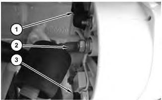
Illustration 1 g06038462
1. Remove cable assembly (1), cable assembly (2), and cable assembly (3).
i06530474
2
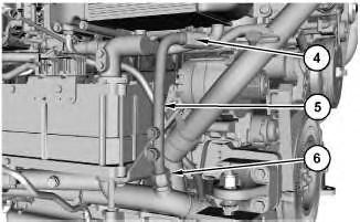
2. Loosen clamp (4). Loosen collar (6) and remove pipe assembly (5).
3
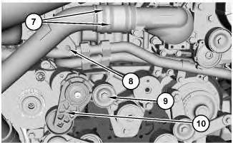
3. Remove clamps (7). Remove bolt (8). Remove pulley (9) and belt tensioner assembly (10).
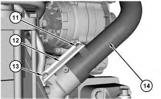
Illustration 4
4. Remove nut (11). Remove Bolt (13) and bracket (12). Remove tube assembly (14).
Illustration
g06011217
Illustration
g06037969
g06038110
5
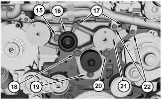
5. Remove pulley (16) and bolt (15). Remove bolts (17) and bolts (22). Remove bolt (18), bolt (19), and bolt (20). Remove support (21).
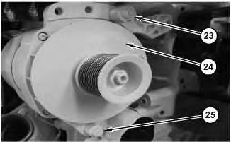
Illustration 6
g06038166
6. Remove nut (23) and bolt (25). Remove alternator assembly (24).
Installation Procedure
1. Install alternator assembly (24) in the reverse order of removal.
a. Tighten bolt (25) to a torque of 46 ± 5 N·m (34 ± 3 lb ft).
b. Tighten bolts (20), (19), (18), and (15) to a torque of 75 ± 8 N·m (55 ± 6 lb ft).
c. Tighten bolt (17) to a torque of 23 ± 2 N·m (204 ± 20 lb in).
d. Tighten belt tensioner assembly (10) to a torque of 62 ± 5 N·m (46 ± 4 lb ft).
e. Tighten pulley (9) to a torque of 45 ± 5 N·m (33 ± 4 lb ft).
f. Tighten clamps (7) to a torque of 3 ± 0.25 N·m (29 ± 2 lb in).
Copyright 1993 - 2024 Caterpillar Inc. All Rights Reserved. Mon Apr 15 12:00:55 UTC+0530 2024
Illustration
g06038148
Product: MARINE ENGINE
Model: C12.9 MARINE ENGINE TPJ
Configuration: C12.9 Marine Engine TPJ00001-UP
Disassembly and Assembly
C12.9 Marine Engines
Electronic Control Module - Remove and Install
SMCS - 1901-010
Removal Procedure
1. Drain the coolant. Refer to Operation and Maintenance Manual,, "Cooling System Coolant (ELC) - Change" for the correct draining and filling procedures..
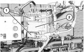
Illustration 1
2. Remove harness assemblies (1) from electronic control module (2).
i06535395
g06011652
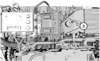
Illustration 2
3. Remove tube assemblies (3).
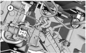
Illustration 3
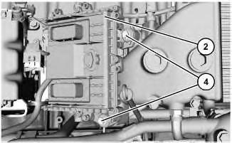
Illustration 4
4. Remove bolts (4). Remove electronic control module (2).
Installation Instructions
1. Install electronic control module (2) in the reverse order of removal.
g06011707
g06011911
g06011912
Product: MARINE ENGINE
Model: C12.9 MARINE ENGINE TPJ
Configuration: C12.9 Marine Engine TPJ00001-UP
Disassembly and Assembly
C12.9 Marine Engines Media
Control Panel - Remove and Install
SMCS - 7451-010
Removal Procedure
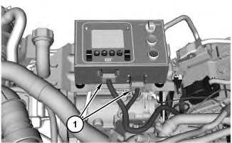
Illustration 1 g06043292 1. Disconnect harness connectors (1).
i06606260
Illustration 2
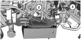
View from above control panel.
g06043327
2. Remove bolts (2) and remove control panel (3).
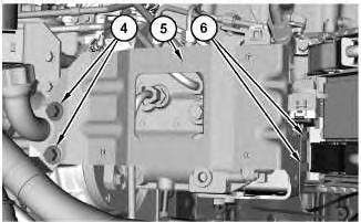
Illustration 3
g06043818
3. Remove bolts (4) and bolts (6). Remove bracket (5).
Installation Procedure
1. Install control panel (3) in the reverse order of removal.
a. Tighten bolts (2) to a torque of 9 ± 1 N·m (80 ± 9 lb in).
Copyright 1993 - 2024 Caterpillar Inc. All Rights Reserved. Private Network For SIS Licensees.
Product: MARINE ENGINE
Model: C12.9 MARINE ENGINE TPJ
Configuration: C12.9 Marine Engine TPJ00001-UP
Disassembly and Assembly
C12.9 Marine Engines
Belt Tensioner - Remove and Install - Accessory Drive Belt
Tensioner
SMCS - 1358-010
Start By:
a. Remove Belt Guard.
Removal Procedure
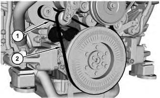
Illustration 1
1. Remove belt (1) and belt (2). Refer to Operation and Maintenance Manual, "BeltsInspect/Replace" for the correct procedure.
i06658392
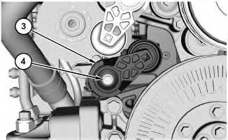
2. Remove bolt (4) and tensioner (3).
Installation Procedure
1. Install tensioner (2) in the reverse order of removal.
a. Tighten bolt (4) to a torque of 68 ± 5 N·m (50 ± 4 lb ft).
Copyright 1993 - 2024 Caterpillar Inc. All Rights Reserved. Private Network For SIS Licensees. Mon Apr 15 12:00:09 UTC+0530 2024
Product: MARINE ENGINE
Model: C12.9 MARINE ENGINE TPJ
Configuration: C12.9 Marine Engine TPJ00001-UP
Disassembly and Assembly
C12.9 Marine Engines
Belt Tensioner - Remove and Install - Damper Drive Belt
Tensioner
SMCS - 1358-010
Start By:
a. Remove Belt Guard.
Removal Procedure
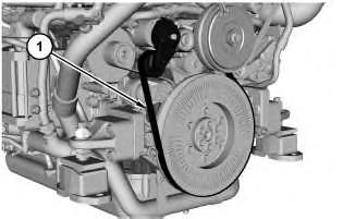
Illustration 1
1. Remove belt (1). Refer to Operation and Maintenance Manual, "Belts - Inspect/Replace" for the correct procedure.
i06657900
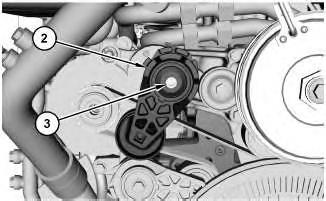
Illustration 2
2. Remove bolt (3) and tensioner (2).
Installation Procedure
1. Install tensioner (2) in the reverse order of removal.
a. Tighten bolt (3) to a torque of 62 ± 5 N·m (46 ± 4 lb ft).
Copyright 1993 - 2024 Caterpillar Inc. All Rights Reserved. Private Network For SIS Licensees. Mon Apr 15 11:59:54 UTC+0530 2024
Product: MARINE ENGINE
Model: C12.9 MARINE ENGINE TPJ
Configuration: C12.9 Marine Engine TPJ00001-UP
Disassembly and Assembly
C12.9 Marine Engines
Belt Tensioner - Remove and Install - Supercharger Drive
Belt Tensioner
SMCS - 1358-010
Start By:
a. Remove Belt Guard.
Removal Procedure
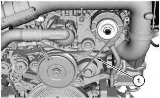
Illustration 1 g06061936
1. Remove belt (1). Refer to Operation and Maintenance Manual, "Belts - Inspect/Replace" for the correct procedure.
i06657655
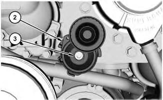
2. Remove bolt (3) and tensioner (2).
Installation Procedure
1. Install tensioner (2) in the reverse order of removal.
a. Tighten bolt (3) to a torque of 61 ± 6 N·m (45 ± 4 lb ft).
Copyright 1993 - 2024 Caterpillar Inc. All Rights Reserved. Private Network For SIS Licensees. Mon Apr 15 11:59:39 UTC+0530 2024
Product: MARINE ENGINE
Model: C12.9 MARINE ENGINE TPJ
Configuration: C12.9 Marine Engine TPJ00001-UP
Disassembly and Assembly
C12.9 Marine Engines
Belt Guard - Remove and Install
SMCS - 1357-010-GD
Removal Procedure
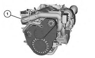
Illustration 1
g06043128
Belt guard is held in place by retention clips only. Grip firmly and apply steady pressure to separate from the engine.
1. Remove belt guard (1).
Installation Procedure
1. Install belt guard (1) in the reverse order of removal. Copyright 1993 - 2024 Caterpillar Inc. All Rights Reserved. Private Network For SIS Licensees. Mon Apr 15 11:59:25 UTC+0530 2024
Product: MARINE ENGINE
Model: C12.9 MARINE ENGINE TPJ
Configuration: C12.9 Marine Engine TPJ00001-UP
Disassembly and Assembly
C12.9 Marine Engines
Idler Pulley - Remove and Install
SMCS - 1358-010
Removal Procedure
Start By:
a. Remove Clutch (Supercharger).
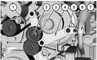
Illustration 1
g06081196
1. Remove bolt (6) and P-clip (7). Remove bolt (2) and idler pulley (3). Remove bolts (5) and bracket (4).
2. Remove belt (1). Refer to Operation and Maintenance Manual, "BeltInspect/Adjust/Replace" to remove and install the belt.
i06701225
2
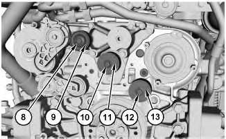
3. Remove bolt (8) and idler pulley (9). Remove bolt (10) and idler pulley (11). Remove bolt (12) and idler pulley (13).
Installation Procedure
1. Install the idler pulley in the reverse order of removal.
a. Tighten bolt (12) to a torque of 105 ± 5 N·m (77 ± 4lb ft).
b. Tighten bolt (10) to a torque of 105 ± 5 N·m (77 ± 4lb ft).
c. Tighten bolt (8) to a torque of 45 ± 5 N·m (33 ± 3 lb ft).
d. Tighten bolt (6) to a torque of 10 ± 1 N·m (89 ± 9 lb in).
e. Tighten bolts (5) to a torque of 25 ± 3 N·m (221 ± 27 lb in).
f. Tighten bolt (2) to a torque of 45 ± 5 N·m (33 ± 3 lb ft). Copyright 1993 - 2024 Caterpillar Inc. All Rights Reserved. Private Network For SIS Licensees.
Product: MARINE ENGINE
Model: C12.9 MARINE ENGINE TPJ
Configuration: C12.9 Marine Engine TPJ00001-UP
Disassembly and Assembly
C12.9 Marine Engines Media
Temperature and Pressure Sensor
(Boost)
- Remove and Install
SMCS - 1439-010-TMS; 1917-010
Removal Procedure
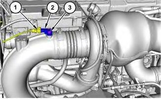
Illustration 1
1. Disconnect harness assembly (1).
g06079622
2. Remove bolt (3) and temperature and pressure sensor (2).
Installation Procedure
1. Install temperature and pressure sensor (2) in the reverse order of removal.
a. Tighten bolt (3) to a torque of 10 ± 1 N·m (89 ± 9 lb in).
Mon Apr 15 11:58:55 UTC+0530 2024
i06693372
Product: MARINE ENGINE
Model: C12.9 MARINE ENGINE TPJ
Configuration: C12.9 Marine Engine TPJ00001-UP
Disassembly and Assembly
C12.9 Marine Engines
Speed Sensor (Supercharger) - Remove and Install
SMCS - 1439-010-VF
Start By:
a. Remove belt guard.
Removal Procedure
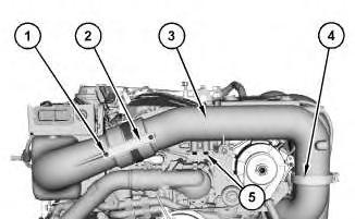
Illustration 1
g06081970
1. Remove bolts (1) and bracket (2). Remove bolts (5). Remove clamp (4) and pipe assembly (3).
i06701846
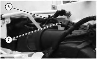
Illustration 2
g06081957
2. Remove cable strap (6). Disconnect harness assembly (7).
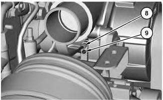
Illustration 3
3. Remove bolt (9) and speed sensor (8).
Installation Procedure
g06081989
1. Install speed sensor (8) in the reverse order of removal.
a. Tighten bolt (9) to a torque of 7 ± 2 N·m (62 ± 18 lb in).
b. Tighten bolts (5) to a torque of 45 ± 5 N·m (33.19020 ± 3.68780 lb ft).
c. Tighten clamp (4) to a torque of 6 ± 0.6 N·m (53 ± 5 lb in).
d. Tighten bolts (1) to a torque of 10 ± 1 N·m (89 ± 9 lb in).
Copyright 1993 - 2024 Caterpillar Inc.
Mon Apr 15 11:58:24 UTC+0530 2024
This is the sample of the manual click on the download link for complete manual
DOWNLOAD LINK
For some reason if link does not work download this pdf and then click