

C1.5DE13.5 GENERATOR SET

Note: Use Bookmarks panel to navigate
C1.5DE13.5 GENERATOR SET
Note: Use Bookmarks panel to navigate
For some reason if link does not work download this pdf and then click

Product: GENERATOR SET
Model: C1.5DE13.5 GENERATOR SET GB9
Configuration: C1.5 DE13.5E3 Generator Set GB900001-UP
Disassembly and Assembly
C1.1, C1.5 and C2.2 Generator Sets
Media Number -KENR9149-01 Publication Date -01/03/2014 Date Updated -04/03/2014
SMCS - 1102-016
Assembly Procedure
Table 1
Required Tools
Personal injury can result from being struck by parts propelled by a released spring force.
Make sure to wear all necessary protective equipment.
Follow the recommended procedure and use all recommended tooling to release the spring force.
Keep all parts clean from contaminants.
Contaminants may cause rapid wear and shortened component life.
1. Ensure that all components are clean and free from wear or damage. Refer to Specifications, "Rocker Shaft" for more information. If necessary, replace any components that are worn or damaged.
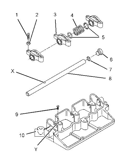
Illustration 1 g01316988
Typical example
2. Lubricate adjustment screw (1) with clean engine oil. Install adjustment screw (1) and nut (2) to rocker arm (3). Repeat the process for the remaining rocker arms.
3. Lubricate rocker shaft (8) with clean engine oil. Position the end of the rocker shaft into the bore of base (10) .
Align hole (X) in the rocker shaft with hole (Y) in base (10) .
4. Gradually insert rocker shaft (8) into base (10). Install rocker arm (3) .
5. Continue to insert rocker shaft (8) and install the following components to the rocker shaft:
Rocker arm (3)
Washer (5)
Spring (4)
Washer (5)
Rocker arm (3)
6. Repeat Steps 5 and 4 in order to install the remaining components.
7. Apply Tooling (A) to the first two threads of screw (9). Install screw (9) in hole (Y) in the base.
Note: Ensure that Tooling (A) is allowed to contaminate the oil gallery in the rocker shaft.
8. Install a new O-ring seal (7) to plug (6) .
9. Install plug (6) to base (10). Tighten the plug to a torque of 15 N·m (11 lb ft).
End By: Install the rocker shaft and the pushrods. Refer to Disassembly and Assembly, "Rocker Shaft and Pushrod - Install".
1993 - 2025 Caterpillar Inc.
Product: GENERATOR SET
Model: C1.5DE13.5 GENERATOR SET GB9
Configuration: C1.5 DE13.5E3 Generator Set GB900001-UP
Disassembly and Assembly
C1.1, C1.5 and C2.2 Generator Sets
Media Number -KENR9149-01
SMCS - 1102-016
Assembly Procedure
-04/03/2014
Personal injury can result from being struck by parts propelled by a released spring force.
Make sure to wear all necessary protective equipment.
Follow the recommended procedure and use all recommended tooling to release the spring force.
NOTICE
Keep all parts clean from contaminants.
Contaminants may cause rapid wear and shortened component life.
1. Ensure that all components are clean and free from wear or damage. Refer to Specifications, "Rocker Shaft" for more information. If necessary, replace any components that are worn or damaged.
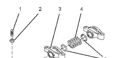
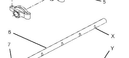
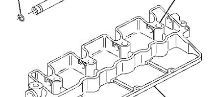

Illustration 1 g01317298
Typical example
2. Lubricate adjustment screw (1) with clean engine oil. Install adjustment screw (1) and nut (2) to rocker arm (3). Repeat the process for the remaining rocker arms.
3. Install a new O-ring seal (7) onto rocker shaft (6). Lubricate the rocker shaft with clean engine oil.
4. Position the end of rocker shaft (6) into the bore in base (8). Align recesses (X) on the rocker shaft with holes (Y) in the base.
5. Gradually insert rocker shaft (6) into the base (8). Install rocker arm (3).
6. Continue to insert rocker shaft (6) and install the following components to the rocker shaft:
Rocker arm (3)
Washer (5)
Spring (4)
Washer (5)
Rocker arm (3)
7. Repeat Steps 5 and 6 in order to install the remaining components.
8. Ensure that rocker shaft (6) is fully engaged into base (8). Check that recesses (X) on the rocker shaft are aligned with holes (Y) in the base.
End By:
a. Install the rocker shaft and the pushrods. Refer to Disassembly and Assembly, "Rocker Shaft and Pushrod - Install". Copyright 1993 - 2025 Caterpillar Inc. All Rights Reserved. Private Network For SIS Licensees. Thu Apr 17 11:23:49 UTC+0530 2025
Product: GENERATOR SET
Model: C1.5DE13.5 GENERATOR SET GB9
Configuration: C1.5 DE13.5E3 Generator Set GB900001-UP
Disassembly and Assembly
C1.1, C1.5 and C2.2 Generator Sets
Media Number -KENR9149-01
Publication Date -01/03/2014
SMCS - 1102-015
Disassembly Procedure
Start By:
Date Updated -04/03/2014
i05689529
A. Remove the rocker shaft and the pushrods. Refer to Disassembly and Assembly, "Rocker Shaft and Pushrod - Remove".
NOTICE
Keep all parts clean from contaminants.
Contaminants may cause rapid wear and shortened component life.
1. Make a temporary identification mark on each rocker arm assembly in order to show the location.
Note: Used components must be reinstalled in the original location. Do not interchange components.
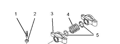
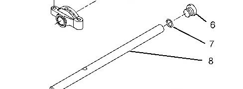
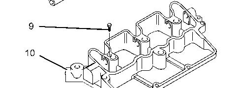

Illustration 1
Typical example
3.
4. In order to remove rocker shaft (8), install a suitable bolt into the end of the rocker shaft. Use the bolt to pull the rocker shaft from base (10) .
Personal injury can result from being struck by parts propelled by a released spring force.
Make sure to wear all necessary protective equipment.
Follow the recommended procedure and use all recommended tooling to release the spring force.
5. Remove rocker arms (3), washers (5), and springs (4) .
6. Remove adjustment screws (1) and nuts (2) from rocker arms (3) .
Copyright 1993 - 2025 Caterpillar Inc. All Rights Reserved. Private Network For SIS Licensees. Thu Apr 17 11:24:06 UTC+0530 2025
Product: GENERATOR SET
Model: C1.5DE13.5 GENERATOR SET GB9
Configuration: C1.5 DE13.5E3 Generator Set GB900001-UP
Disassembly and Assembly
C1.1, C1.5 and C2.2 Generator Sets
Media Number -KENR9149-01
Publication Date -01/03/2014
Date Updated -04/03/2014
SMCS - 1102-015
Disassembly Procedure
Start By:
i02602652
a. Remove the rocker shaft and the pushrods. Refer to Disassembly and Assembly, "Rocker Shaft and Pushrod - Remove".
NOTICE
Keep all parts clean from contaminants.
Contaminants may cause rapid wear and shortened component life.
1. Make a temporary identification mark on each rocker arm assembly in order to show the location.
Note: Used components must be reinstalled in the original location. Do not interchange components.
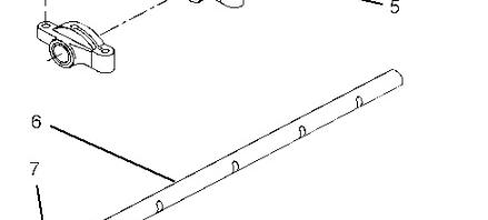
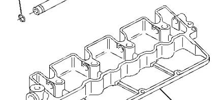
Illustration 1 g01317304
Typical example
2. In order to remove rocker shaft (6), install a suitable bolt into the end of the rocker shaft. Use the bolt to pull the rocker shaft from base (8).
Personal injury can result from being struck by parts propelled by a released spring force.
Make sure to wear all necessary protective equipment.
Follow the recommended procedure and use all recommended tooling to release the spring force.
3. Remove rocker arms (3), washers (5), and springs (4).
4. Remove O-ring seal (7) from rocker shaft (6).
5. Remove adjustment screws (1) and nuts (2) from rocker arms (3).
1993 - 2025 Caterpillar Inc.
Rights Reserved.
Network For SIS Licensees. Thu Apr 17 11:24:21 UTC+0530 2025
Product: GENERATOR SET
Model: C1.5DE13.5 GENERATOR SET GB9
Configuration: C1.5 DE13.5E3 Generator Set GB900001-UP
Disassembly and Assembly
C1.1, C1.5 and C2.2 Generator Sets
Media Number -KENR9149-01
Publication Date -01/03/2014
SMCS - 1102-012; 1208-012
Installation Procedure Table 1
Required Tools
Tool Part Number Part Description Qty A 266-9682 White Compound 1
NOTICE
Keep all parts clean from contaminants.
Date Updated -04/03/2014
Contaminants may cause rapid wear and shortened component life.
1. Ensure that all components are clean and free from wear or damage. Refer to Specifications, "Rocker Shaft" for more information. Replace any components that are worn or damaged.
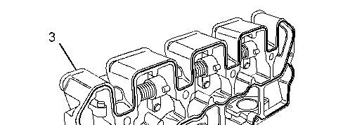
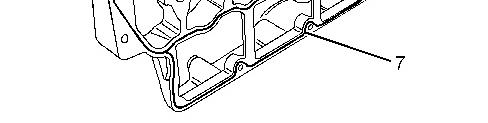
Illustration 1 g01317309
Typical example
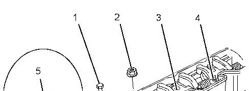
2. Apply Tooling (A) to the new joint. Install a new joint (7) to the base of rocker shaft assembly (3) .

Typical example
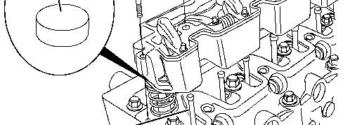
3. Apply clean engine lubricating oil to both ends of pushrods (6). Install the pushrods to the engine with the cup upward. Ensure that the pushrods are installed correctly in the socket of the valve lifters.
Note: If the pushrods have been used, ensure that the pushrods are installed in original positions.
4. Lubricate the top of the valve stems with clean engine oil. Install caps (5) to the valve stems.
Note: If the caps have been used, ensure that the caps are installed in original positions.
5. Install rocker shaft assembly (3) to the cylinder head.
Note: Ensure that the ends of adjustment screws (4) are correctly seated in ends of pushrods (6) .
6. Install nuts (2). Use a deep socket to evenly tighten the nuts. Begin at the center of the rocker shaft and work outward.
For C1.1 engines, tighten nuts (2) to a torque of 23 N·m (17 lb ft).
For C1.5, and C2.2 engines, tighten nuts (2) to a torque of 33 N·m (24 lb ft).
7. Install bolts (1) and tighten to a torque of 10 N·m (88 lb in).
8. Adjust the valve lash. Refer to Systems Operation, Testing and Adjusting, "Engine Valve Lash - Inspect/Adjust" for the correct procedure.
End By:
a. Install the valve mechanism cover. Refer to Disassembly and Assembly, "Valve Mechanism Cover - Remove and Install".
b. Install the engine oil line. Refer to Disassembly and Assembly, "Engine Oil Line- Remove and Install".
Product: GENERATOR SET
Model: C1.5DE13.5 GENERATOR SET GB9
Configuration: C1.5 DE13.5E3 Generator Set GB900001-UP
Disassembly and Assembly
C1.1, C1.5 and C2.2 Generator Sets
Media Number -KENR9149-01
Publication Date -01/03/2014
SMCS - 1357-010
Removal Procedure
Date Updated -04/03/2014
i02602656
NOTICE
Keep all parts clean from contaminants.
Contaminants may cause rapid wear and shortened component life.
1. If the engine is equipped with fan guards, remove the fan guards.
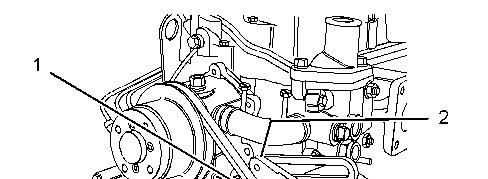
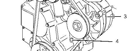

Illustration 1 g01325726
Typical example
2. Loosen bolts (1), (2) and (4).
3. Push alternator (3) toward the engine and remove V-belt (5).
Note: Mark the direction of rotation if the V-belt will be reused.
Keep all parts clean from contaminants.
Contaminants may cause rapid wear and shortened component life.
Illustration 2 g01325726
Typical example
1. Check the condition of the V-belt . If the V-belt is worn or damaged, use a new V-belt for replacement.
2. Install V-belt (5) in position on the engine.
Note: A used V-belt should be installed in the original direction of rotation.
3. Slide alternator (3) away from the engine. Refer to Systems Operation, Testing and Adjusting, "Belt Tension Chart" for information on the correct belt tension. Tighten bolts (1), (2) and (4) to a torque of 25 N·m (18 lb ft).
4. If the engine is equipped with fan guards, install the fan guards. Copyright 1993 - 2025 Caterpillar Inc.
Network For SIS Licensees. Thu Apr 17 11:15:50 UTC+0530 2025
Product: GENERATOR SET
Model: C1.5DE13.5 GENERATOR SET GB9
Configuration: C1.5 DE13.5E3 Generator Set GB900001-UP
Disassembly and Assembly
C1.1, C1.5 and C2.2 Generator Sets
Media Number -KENR9149-01
Publication Date -01/03/2014
Date Updated -04/03/2014
SMCS - 1405-010
Removal Procedure
Start By:
a. Remove the V-Belt. Refer to Disassembly and Assembly, "V-Belts - Remove and Install".
Keep all parts clean from contaminants.
Contaminants may cause rapid wear and shortened component life.
1. Turn the battery disconnect switch to the OFF position.
2. Make temporary identification marks on the connections of the harness assembly.
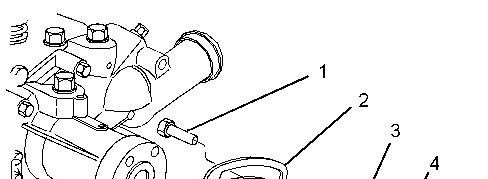
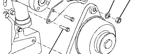

Illustration 1 g01308275
Typical example
3. Disconnect the harness assembly (not shown) from alternator (6).
4. Remove bolt (1), washer (3) and nut (4) from alternator (6).
5. Remove bolt (7) and remove alternator (6) from the engine.
6. If necessary, remove bolts (5) and remove adjusting link (2).
Note: The adjusting link on some engines is secured by one bolt.
Installation Procedure
Illustration 2 g01308275
Typical example
1. If necessary, install adjusting link (2) and install bolts (5) finger tight.
Note: The adjusting link on some engines is secured by one bolt.
2. For engines that have an adjusting link that is secured by one bolt, leave bolt (5) loose. For engines that have an adjusting link that is secured by two bolts, tighten bolts (5) to a torque of 10 N·m (89 lb in).
3. Position alternator (6) on the engine and install bolt (7) finger tight.
4. Install bolt (1), washer (3) and nut (4) finger tight.
5. Install the V-Belt. Refer to Disassembly and Assembly, "V-Belts - Remove and Install".
Note: Ensure that the alternator pulley is in alignment with the crankshaft pulley. Ensure that all fasteners are tightened.
6. Connect the harness assembly (not shown) to the alternator.
7. Turn the battery disconnect switch to the ON position.
Product: GENERATOR SET
Model: C1.5DE13.5 GENERATOR SET GB9
Configuration: C1.5 DE13.5E3 Generator Set GB900001-UP
Disassembly and Assembly
C1.1, C1.5 and C2.2 Generator Sets
Media Number -KENR9149-01 Publication Date -01/03/2014 Date Updated -04/03/2014
SMCS - 1405-010
Removal Procedure
Start By:
a. Remove the V-Belt. Refer to Disassembly and Assembly, "V-Belts - Remove and Install".
NOTICE
Keep all parts clean from contaminants.
Contaminants may cause rapid wear and shortened component life.
1. Turn the battery disconnect switch to the OFF position.
2. Make temporary identification marks on the connections of the harness assembly.
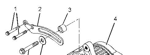
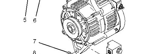

Illustration 1 g01308278
Typical example
3. Disconnect the harness assembly (not shown) from alternator (4).
4. Remove bolt (5), washer (6) and spacer (3) from alternator (4).
5. Remove bolt (8) and washer (7). Remove the alternator (4) from the mounting bracket.
6. If necessary, remove bolts (1) and remove adjusting link (2).
For some reason if link does not work download this pdf and then click