Product:ASPHALTPAVER
Model:BG1055EASPHALTPAVERFRR
Configuration:AP1055EBG1055EAsphaltPaverFRR00001-UP(MACHINE)POWEREDBYC7.1Engine
OperationandMaintenanceManual
Topcon®SystemFive
MediaNumber-KEBU7018-12PublicationDate-01/10/2014DateUpdated-10/09/2019
Foreword
CaliforniaProposition65Warning
DieselengineexhaustandsomeofitsconstituentsareknowntotheStateofCaliforniato causecancer,birthdefects,andotherreproductiveharm.
WARNING-Thisproductcanexpose youtochemicalsincludingethylene glycol,whichisknowntotheStateof Californiatocausebirthdefectsorother reproductiveharm.Formoreinformation goto:
www.P65Warnings.ca.gov
Donotingestthischemical.Washhandsafterhandlingtoavoidincidentalingestion.
WARNING-Thisproductcanexpose youtochemicalsincludingleadandlead compounds,whichareknowntothe StateofCaliforniatocausecancer,birth defects,orotherreproductiveharm.For moreinformationgoto:
www.P65Warnings.ca.gov
Washhandsafterhandlingcomponentsthatmaycontainlead.
LiteratureInformation
s03548206
Thismanualshouldbestoredintheoperator'scompartmentintheliteratureholderorseatback literaturestoragearea.
Thismanualcontainssafetyinformation,operationinstructions,transportationinformation, lubricationinformation,andmaintenanceinformation.
Somephotographsorillustrationsinthispublicationshowdetailsorattachmentsthatcanbe differentfromyourmachine.Guardsandcoversmighthavebeenremovedforillustrative purposes.
Continuingimprovementandadvancementofproductdesignmighthavecausedchangestoyour machinewhicharenotincludedinthispublication.Read,study,andkeepthismanualwiththe machine.
Wheneveraquestionarisesregardingyourmachine,orthispublication,pleaseconsultyourCat dealerforthelatestavailableinformation.
Safety
Thesafetysectionlistsbasicsafetyprecautions.Inaddition,thissectionidentifiesthetextand locationsofwarningsignsandlabelsusedonthemachine.
Readandunderstandthebasicprecautionslistedinthesafetysectionbeforeoperatingor performinglubrication,maintenance,andrepaironthismachine.
Operation
Theoperationsectionisareferenceforthenewoperatorandarefresherfortheexperienced operator.Thissectionincludesadiscussionofgauges,switches,machinecontrols,attachment controls,transportation,andtowinginformation.
Photographsandillustrationsguidetheoperatorthroughcorrectproceduresofchecking,starting, operating,andstoppingthemachine.
Operatingtechniquesoutlinedinthispublicationarebasic.Skillandtechniquesdevelopasthe operatorgainsknowledgeofthemachineanditscapabilities.
Maintenance
Themaintenancesectionisaguidetoequipmentcare.TheMaintenanceIntervalSchedule(MIS) liststheitemstobemaintainedataspecificserviceinterval.Itemswithoutspecificintervalsare listedunderthe"WhenRequired"serviceinterval.TheMaintenanceIntervalScheduleliststhe pagenumberforthestep-by-stepinstructionsrequiredtoaccomplishthescheduledmaintenance. UsetheMaintenanceIntervalScheduleasanindexor"onesafesource"forallmaintenance procedures.
MaintenanceIntervals
Usetheservicehourmetertodetermineservicingintervals.Calendarintervalsshown(daily, weekly,monthly,etc.)canbeusedinsteadofservicehourmeterintervalsifthecalendarintervals
providemoreconvenientservicingschedulesandapproximatetheindicatedservicehourmeter reading.Performtherecommendedserviceattheintervalthatoccursfirst.
Undersevere,dusty,orwetoperatingconditions,morefrequentlubricationthanisspecifiedinthe maintenanceintervalschartmightbenecessary.
Performserviceonitemsatmultiplesoftheoriginalrequirement.Forexample,atevery500 servicehoursor3months,alsoservicethoseitemslistedunderevery250servicehoursor monthlyandevery10servicehoursordaily.
CertifiedEngineMaintenance
Propermaintenanceandrepairareessentialtokeeptheengineandmachinesystemsoperating correctly.Astheheavy-dutyoff-roaddieselengineowner,youareresponsibleforthe performanceoftherequiredmaintenancelistedintheOwnerManual,OperationandMaintenance Manual,andServiceManual.
Itisprohibitedforanypersonengagedinthebusinessofrepairing,servicing,selling,leasing,or tradingenginesormachinestoremove,alter,ortorenderinoperative,anyemission-relateddevice orelementofdesigninstalledonorinanengineormachinethatisincompliancewithall applicableregulationsoftheintendedcountrytowhichithasbeenshipped.Certainelementsof themachineandenginesuchastheexhaustsystem,fuelsystem,electricalsystem,intakeair system,andcoolingsystemmaybeemission-relatedandshouldnotbealteredunlessapprovedby Caterpillar.
MachineCapacity
Additionalattachmentsormodificationsmayexceedmachinedesigncapacitywhichcan adverselyaffectperformancecharacteristics.Includedwouldbestabilityandsystemcertifications suchasbrakes,steering,androlloverprotectivestructures(ROPS).ContactyourCatdealerfor furtherinformation.
ProductIdentificationNumber
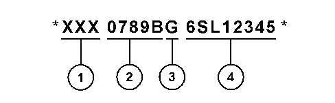
EffectiveFirstQuarter2001theProductIdentificationNumber(PIN)haschangedfrom8to17 characters.Toprovideuniformequipmentidentification,constructionequipmentmanufacturers aremovingtocomplywiththelatestversionoftheproductidentificationnumberingstandard. Non-roadmachinePINsaredefinedbyISO10261.ThenewPINformatwillapplytoall machinesandgeneratorsets.ThePINplatesandframemarkingwilldisplaythe17characterPIN. Thenewformatwilllooklikethefollowing:
This is the sample of the manual if you need complete manual Click Here to download
Where:
1.WorldManufacturingCode(characters1-3)
2.MachineDescriptor(characters4-8)
3.CheckCharacter(character9)
4.MachineIndicatorSection(MIS)orProductSequenceNumber(characters10-17).Thesewere previouslyreferredtoastheSerialNumber.
MachinesandgeneratorsetsproducedbeforeFirstQuarter2001willmaintaintheir8character PINformat.
Componentssuchasengines,transmissions,axles,andworktoolswillcontinuetousean8 characterSerialNumber(S/N).
Copyright1993-2023CaterpillarInc. AllRightsReserved. PrivateNetworkForSISLicensees.
ThuMay2522:30:27UTC+05302023
Product:ASPHALTPAVER
Model:BG1055EASPHALTPAVERFRR
Configuration:AP1055EBG1055EAsphaltPaverFRR00001-UP(MACHINE)POWEREDBYC7.1Engine
OperationandMaintenanceManual
Components-Clean/Inspect
SMCS-7220-040;7220-070;7220-571
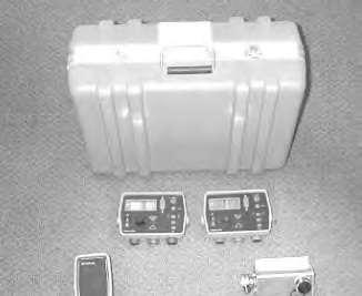
Keepthecarryingcasedryandstorethecarryingcaseinadry location.Neverletthecarryingcasebecomewet.Ifthecasebecomes wet,removethecomponentsandairuntildry.Moistureinthe componentscancausecorrosionresultinginequipmentfailure.
WipetheTopcon®SystemFivecomponentsandcleantheTopcon®SystemFiveattheendofthe day.Placethecomponentsandthecoilcordsintheappropriatesectionsofthecarryingcasefor storage.Thiswillensuretheintegrityofthesecomponentsandproperstoragewillprotectthe componentsfromvandalismortheft.
Copyright1993-2023CaterpillarInc. AllRightsReserved. PrivateNetworkForSISLicensees.
ThuMay2522:34:48UTC+05302023
Product:ASPHALTPAVER
Model:BG1055EASPHALTPAVERFRR
Configuration:AP1055EBG1055EAsphaltPaverFRR00001-UP(MACHINE)POWEREDBYC7.1Engine
OperationandMaintenanceManual Topcon®SystemFive
MediaNumber-KEBU7018-12PublicationDate-01/10/2014DateUpdated-10/09/2019 i05959475
MaintenanceIntervalSchedule
SMCS-7000;7220
WhenRequired
Transducer-Clean/Inspect Transducer-Replace
Every10ServiceHoursorDaily
Components-Clean/Inspect
Every1000ServiceHoursor1Year
Transducer-Replace
Copyright1993-2023CaterpillarInc. AllRightsReserved. PrivateNetworkForSISLicensees.
ThuMay2522:34:38UTC+05302023
Product:ASPHALTPAVER
Model:BG1055EASPHALTPAVERFRR
Configuration:AP1055EBG1055EAsphaltPaverFRR00001-UP(MACHINE)POWEREDBYC7.1Engine
OperationandMaintenanceManual
Topcon®SystemFive
MediaNumber-KEBU7018-12PublicationDate-01/10/2014DateUpdated-10/09/2019
GradeandSlopeControlSystemTroubleshooting
SMCS-7000-035;7220-035
SetupProcedure
UseextremecautionwhenyouoperatetheTopcon®System.The Topcon®Systemwillautomaticallyraiseorlowerthetowarmandthe screed.Failuretoobservetheautomaticoperationofthetowarmand thescreedmayresultinpersonalinjuryordeath.
1.Placethescreedontheground.
2.MovethetowpointcylinderstotheCENTERposition.
3.Turnofftheengine.EnsurethatallswitchesareintheOFFposition.Makesurethatthe brakesareapplied.
NOTICE
Properinstallationofelectricalcomponentsisnecessarytoprevent componentdamage.Topreventelectricalcomponentdamage,turnthe enginestartswitchtotheOFFpositionbeforeconnectingor disconnectingelectricalcomponents.Failuretofollowthisprocedure mayresultinelectricalcomponentdamage.
i02710832
4.MounttheTopcon®SystemFivecomponentsonthemachineandattachtheconnectors properly.
5.Thescreedshouldbenulledonbothsides.
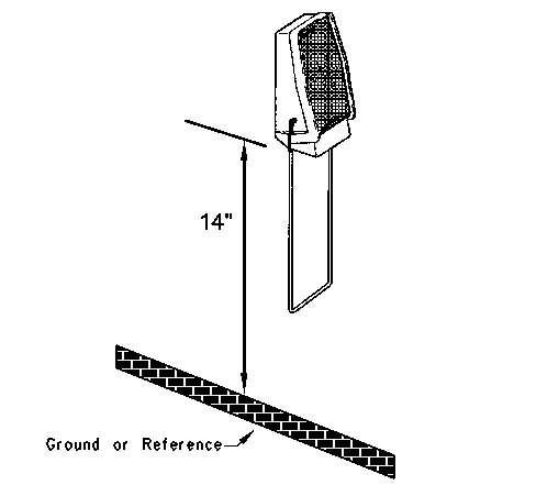
6.PositiontheSonicTrackerII®14inchesabovetheground.Installthetemperaturebailson bothoftheSonicTrackerII®sensors.
7.Starttheengineandruntheengineathighidle.
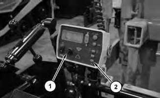
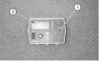
Illustration2g00834365
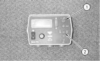
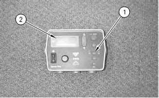
Illustration1g00834352
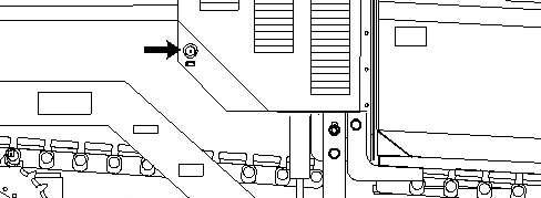
(1)Auto/manualbutton
(2)Grade/slopeelevationbutton
8.PutthespeedcontrolintothePAVEposition.
9.Engagethebrakes.Placethepropelleverforward.Turnthespeedpotentiometerat1/2.
Note:FortheAP-800,AP-900B,BG-240C,andBG-230AsphaltPavers,turnthespeed potentiometerto"0".Placethetravelleverforward.Releasethebrakes.
10.TurnbothofthecontrolboxestotheONposition.
11.Depressauto/manualbutton(1)andselecttheMANUALpositiononbothofthecontrol boxes.
CheckingtheGrade
Illustration7g00828252
1.Thecontrolboxshouldgiveasingleaudiblebeep.
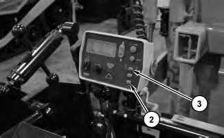
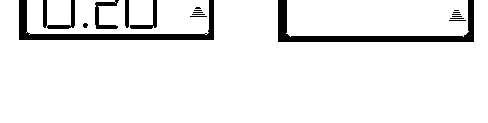
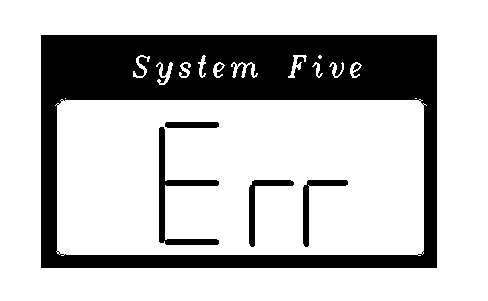
2.LCDdisplay(2)shouldcomeon.
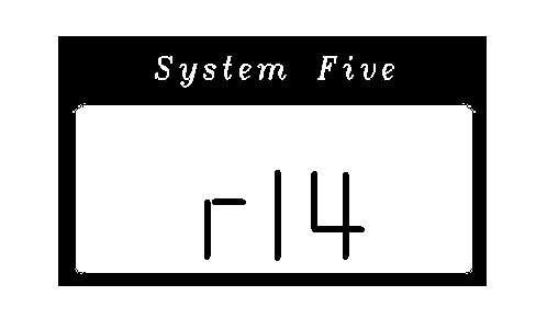
Illustration8g00827168
a.Adigitalnumbershouldappear.Thisistherevisionnumberforthesoftwarethatis currentlyusedwiththeTopcon®SystemFive.
b.Aconfigurationnumbershouldappearnext.
Note:Thedisplayshouldalwaysshowthecorrectconfigurationnumber.Thesame configurationnumberislistedinthemachinemodelchart.ObservetheLCDdisplay. Theconfigurationnumbershouldappear.Iftheconfigurationnumberdoesnot appear,thepowercablemaybebad.
Illustration9g00827182
Illustration10g00827198
c.Thedisplayshouldmomentarilydisplayan"Err".
3.Makesurethatthecontrolboxissettograde.Thisisdonebyusingthegradeorthe elevationbutton(1).
Note:If"Err"isdisplayedcontinuously,thecontrolboxisnotabletocommunicatewith theSonicTrackerII®.Checkthecableandtheconnections.
Illustration11g00827204
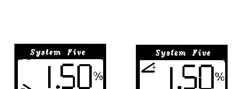
4.TheTrackersymbolinthelowerrightcorneroftheLCDdisplayshouldappear.
Illustration12g00828190
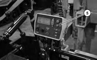
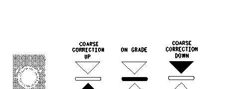
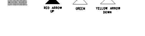
5.ThegradeadjustmentLEDmayshowaredarrowthatpointsupward,agreenlinethatis straight,orayellowarrowthatpointsdownward.Ifthesystemisnot"OnGrade",the arrowswillilluminateabovethegradeadjustmentknob.
Illustration13g00815833
6.ThesymbolforthetemperaturebailshouldbedisplayedontheSonicTrackerII®.
Note:IfthebailindicatordoesnotappearandthebailisattachedtotheSonicTrackerII®, thetransducermaybefailing.
7.TheSonicTrackerII®shouldemitatickingsound.
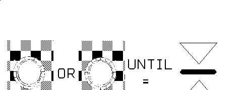
Illustration14g00828229
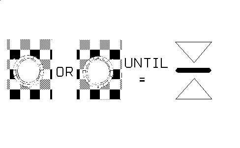
a.Adjustthegradebyturningthegradeadjustmentknobinthedirectionofthearrows. The"OnGrade"symbolshouldilluminateonthegradeadjustmentLEDafterthe systemis"OnGrade".
Illustration15g00828246
b.ObservetheLEDdisplayontheSonicTrackerII®andthegradeadjustmentLEDon thecontrolbox.Thedisplaysshouldnowread"OnGrade".
c.Depresstheauto/manualbutton.Selecttheautomode.
d.Slowlypushasmallobjectthatis25mm(1inch)orlessunderthegradesensor.
e.ThegreenuparrowonthegradeadjustmentLEDshouldilluminateandtheSonic TrackerII®shoulddisplayanuparrow.Thetowpointcylindershouldmoveuptoa newpositionandstop.
f.Removetheobjectthatisunderthegradesensors.
g.TheyellowdownarrowonthegradeadjustmentLEDshouldilluminateandtheSonic TrackerII®shoulddisplayadownarrow.Thetowpointcylindershouldmovedown totheoriginalpositionandstop.
Note:Thevalveoffsetsmayrequiresmalladjustmentsifthetowpointcylinderdoes notstop.Adjustmentswillneedtobemadeifthetowpointmovesintheopposite directioninordertofindthenewgrade.
CheckingtheSlope
Illustration17g00827168
a.Adigitalnumbershouldappear.Thisistherevisionnumberofthesoftware.
Illustration18g00827182
b.Aconfigurationnumbershouldappearnext.
Note:Thedisplayshouldalwaysshowthecorrectconfigurationnumber.The configurationnumberislistedinthemachinemodelchart.Ifadifferentnumber appearsonthedisplay,thepowercablecouldbebad.
Illustration19g00827198
c.TheLCDdisplayshouldmomentarilydisplayan"ERR".
Note:If"Err"isdisplayedcontinuously,thecontrolboxisnotabletocommunicate withtheSonicTrackerII®.Checkthecableandtheconnections.
3.Makesurethatyousettheslopeonthecontrolboxbyusinggrade/slopeelevationbutton (1).
4.LCDdisplay(2)shouldcomeon.
Illustration20g00828296
a.The"+Slope"or"-Slope"symbolsshouldbedisplayed.Adigitalsymbolshould appearandthe"%"symbolshouldbevisible.
Illustration21g00828229
5.Adjusttheslopedisplaybyturningthegradeadjustmentknobinthedirectionofthe illuminatedarrows.The"OnGrade"symbolshouldilluminateonthegradeadjustmentLED afterthesystemis"OnGrade".
6.Depresstheauto/manualbutton.Selecttheautomaticmode.
7.Turnthegradeadjustmentknob.Turn1clickintheclockwisedirection.Thegrade adjustmentLEDshouldilluminateonthecontrolbox.Thetowpointcylindershouldmove downtoanewpositionandstopwith2to3secondsasthegradeadjustmentLED illuminates.
8.Turnthegradeadjustmentknob.Turn2clickscounterclockwiseor3clicks counterclockwise.ThegradeadjustmentLEDshouldchangeandthegreenuparrowshould illuminate.Thetowpointcylindershouldmoveuptoanewpositionandstopwith2to3 secondsasthegradeadjustmentLEDilluminates.
9.Turnofftherightcontrolbox.Repeatthechecksfortheslopeontheleftsideofthepaver.
CheckingthePerformanceoftheSystem FineTuningtheOffsets
1.Movethemachinetoasurfacethatisflat.Lowerthescreedtotheground.Pullthemachine slightlyforward.Thiswilltaketheslackoutofthetowpoint.
Illustration22g00828246
Illustration23g00783086
2.MovethetowpointcylinderstotheCENTERposition.
3.MovethescreedthicknesscontrolstotheNULLposition.
4.Thefollowingconditionsmustbemetduringtheperformancecheck:
a.Theenginemustbeathighidle.
b.Thehydraulictemperaturemustbeat38°C(100°F).
c.EnsurethattheparkingbrakeisintheONposition.
d.Setthespeedpotentiometerat1/2.
e.Pushthepropelleverforward.
f.TheTopcon®SystemFivecontrolsystemmustbeactive.
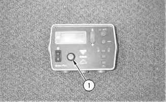
Illustration24g00828252
5.PutthecontrolboxintheSLOPEpositionbyusinggrade/slopebutton(1).Theslopeneeds tobenull.Ensurethattheslopeisoperatingproperly.RefertoOperationandMaintenance Manual,"CheckingtheSlope"foramoredetaileddescriptionofthenullprocedure.
6.Presstheauto/manualbutton.
7.Turngradeadjustmentknob(1)clockwisebyoneclickandobservethemovementofthe towpoint.
Note:Thecylindershouldmovetothenewlocationintwoorthreeseconds.Ifthecylinder doesnotmakeacompletechangeintwoorthreeseconds,youshouldincreasetheoffsetof thevalve.Ifthecylindermovestoofast,youshoulddecreasetheoffsetofthevalve.Ifthe cylinderovershootsthecorrectpositionandthecylinderthenreturns,youshoulddecrease theoffsetofthevalve.
Note:ThevalveoffsetsshouldbesetwiththetowpointcylindersattheCENTERposition.
8.Accessthemenufortheperformance.Makethechangesthatarerequiredtotheoffsets. Thisshouldbedoneuntilyouhavemetthecriteriaforsystemperformance.
9.Repeattheprocedurefortheoppositedirection.
10.Repeattheprocedurefortheoppositesideofthemachine.
Diagnostics
ProceduresforTroubleshootingtheSonicTrackerII®
TheproblemisaseriesofthreedashesontheSonicTrackerII®displayoraunitthatwill notadjustto"OnGrade".
Theprobablecausemaybelistedbelow.
1.Thethreedashesappearwhenthecontrolboxisthe"SURVEY"modeandtheSonic TrackerII®isreportingnoecho.
2.TheSonicTrackerII®isnotpointedatatargetthatiswithintherangeof14-24inches.
3.Thetargetmaybetooclose.Ifthetargetiswithin9to10inchesfromtheSonicTracker II®,thetargetwillbeinterpretedasatemperaturebail.
4.Youmustdecideifthetransduceristransmitting.Thequestioncanbeansweredwiththe followingparagraph.
Thetransduceremitsapingingnoise.Thesoundisaudible.Ifnopingingnoiseisaudible, replacethetransducer.RefertoOperationandMaintenanceManual,"SonicTrackerIIReplace"foramoredetaileddescriptionofthismaintenanceprocedure.Ifalltheabove checksareok,thenthetransducermaybeworkingpoorlyduetodirtordamage.Referto theOperationandMaintenanceManual,"Components-Clean/Inspect"foramoredetailed descriptionofthismaintenanceprocedure.
TheproblemisaSonicTrackerII®witherraticheightmeasurements.Thetargetis positionedproperly.
Theprobablecausemaybelistedbelow.
1.Placethecontrolboxinthe"SURVEY"mode.Thiswilldeterminetheamountoferratic measurements.Ifthenumberonthedisplayisblinkingafewtimes,thesystemisprobably justtakinginairortakinginvibration.Theuseofthetemperaturebailandareductionin thevibrationofthescreedmightbenecessary.LoweringtheSonicTrackerII®356mm (14inch)overthetargetmayalsohelp.
2.Checkforothersurfacesthatarereadbythesensor.Thisshouldbedonewhenthenumber onthedisplayblinksbyalargedegree.Anexampleoftheothersurfaceisaroadconeora screedendgate.Smallstringandwirecanbeusedastargets.Theimageofthestringmay notberead.TheSonicTrackerII®willsensethegroundinstead.
3.Theproblemcouldbemarginaltransducerreceptionorintermittenttransducerreceptionif thenumberonthedisplayalternatesbetweenavalidnumberandthreedashes.Checkthe connectionsonthetransducerand/orreplacethetransducer.RefertoOperationand MaintenanceManual,"SonicTrackerII-Replace"orOperationandMaintenanceManual, "Components-Clean/Inspect"foramoredetaileddescriptionofthemaintenance proceduresinthismanual.
TheproblemisaLCDdisplaywith"ERR"onthedisplay.
Theprobablecausemaybelistedbelow.
1.Thesymbol"ERR"isdisplayedwhenthecontrolboxcannotseetheSonicTrackerII®.The mostlikelycauseoftheerroristhecableconnectionattheSonicTrackerII®orthecable connectionatthecontrolbox.Changethecablesfromonesidetotheotherside.Disconnect thecablesandinspectthecablesfordamageorcontamination.RefertoOperationand maintenanceManual,"Components-Clean/Inspect"foramoredetaileddescriptionofthis maintenanceprocedure.
2.Thesymbol"ERR"isdisplayediftheSonicTrackerII®hasfailed.ReplacetheSonic TrackerII®withtheoppositesideSonicTrackerII®andobservetheoperation.
3.Changethecontrolboxesfromonesidetotheotherside.Observetheoperationofthe controlbox.
4.Thesymbol"ERR"isdisplayedwhenthecontrolcannotseetheslopesensor.Themost likelycauseofthisfailureisthecableortheconnections.Changethecablesfortheslope fromonesidetotheotherside.
5.Changethesidesforslopeoperation.Thismayresolvetheproblem.Iftheslopehasbeen selected,checkthattheslopehasnotbeenselectedontheothercontrolbox.Iftheproblem isnotresolved,replacetheslopesensor.Iftheproblemisresolved,replacethecontrolbox.
6.Iftheelevationhasbeenselected,replacetheSonicTrackerII®and/orthecables.Usethe unitfromtheoppositesideinordertodetermineifthesymptomsstillpersist.
Theproblemisatowpointcylinderwithfastmovement.Theproblemisatowpoint cylinderwithslowmovement.
Theprobablecausemaybelistedbelow.
Thesystemperformancesettingsmaybeincorrect.
Adjustthefollowingmenuitemstotherecommendedsettings:"Gain","Deadband","Valve Offset"and"PerformanceSettings".
Theproblemisaslopesensorwithanincorrectcalibration.
Theprobablecausemaybelistedbelow.
1.Calibratetheslopesensor.RefertoOperationandMaintenanceManual,"ControlBox". Thissectionincludesinformationoncalibratingthefollowingcomponents:SonicTracker II®,contactsensorandslopesensor.
2.Checkthatthetransversebeamismountedproperlywithnoloosenessordamage.
3.Recheckthegradebyusingagoodreference.Anexampleofagoodreferencewouldbea laseroralevel.
Theproblemisatowpointcylinderwithadrift.Thetowpointwilldriftupwardorthetow pointwilldriftdownward.
Theprobablecausemaybelistedbelow.
1.Placetheengineat"FULL"throttle.
2.Extendthecylinderallthewayanddisconnectthehosethatleadstotherodendofthetow pointcylinder.
3.Carefullypushdownonthejogswitchforthetowpoint.
4.Observethefittingonthecylinder.Observeifanyfluidcomesoutofthefitting.Checkthe cylinderforapistonthathasblownpacking.
5.Ifnofluidcomesoutofthefitting,thenthereisafaultyholdingvalve. Copyright1993-2023CaterpillarInc.
Product:ASPHALTPAVER
Model:BG1055EASPHALTPAVERFRR
Configuration:AP1055EBG1055EAsphaltPaverFRR00001-UP(MACHINE)POWEREDBYC7.1Engine
OperationandMaintenanceManual
Topcon®SystemFive
MediaNumber-KEBU7018-12PublicationDate-01/10/2014DateUpdated-10/09/2019
Transducer-Clean/Inspect
SMCS-1904-571;7220-571
i02457225
Note:Thisprocedureisnotmeanttobearegularmaintenanceprocedure.Cleanthetransducer onlywhencontaminationissuspectedorcontaminationisevident.
Note:Cleaningthetransducertoomuchwillshortenthelifeofthetransducer.Cleaningthe transducertoomuchmayalsodamagethesonicdetectionunit.
UsethefollowingproceduretocleantheSonicTrackerII®Transducer.
1.Holdthesonicdetectionunitinanuprightpositioninordertopreventmoisturefrom inadvertentlyenteringthesonicdetectionunit.
2.Mixamilddetergentwithwaterandplacethesolutioninasquirtbottle.
Note:CaterpillarrecommendstheuseofSimpleGreen®detergent.
3.Whileyouholdthesonicdetectionunitupright,thoroughlyspraythetransducerwiththe solution.
4.Aftersprayingthetransducerwiththesolution,fillthesquirtbottlewithcleanwater.Rinse offanyresidualdetergentonthetransducer.
5.Allowthesonicdetectionunittothoroughlydry.
Copyright1993-2023CaterpillarInc. AllRightsReserved. PrivateNetworkForSISLicensees.
ThuMay2522:34:59UTC+05302023
Product:ASPHALTPAVER
Model:BG1055EASPHALTPAVERFRR
Configuration:AP1055EBG1055EAsphaltPaverFRR00001-UP(MACHINE)POWEREDBYC7.1Engine
OperationandMaintenanceManual
MediaNumber-KEBU7018-12PublicationDate-01/10/2014DateUpdated-10/09/2019
Transducer-Replace
SMCS-7220-510-KIT
i01573743
Note:IftheSonicTrackerII®isexperiencingerraticreadingsorinconsistentreadings, contaminationofthetransducershouldbeconsideredfirstbeforeyouassumeanyothertypeof failure.Themostcommonwarningsignofcontaminationinthetransduceristheabilityofthe SonicTrackerII®toseetheground,butnotastringline.
Theonlytoolsthatareneededforthisprocedureareacrosstipscrewdriverandasmallpairof cutters.Thetransducercanbereplacedwiththefollowingprocedure:
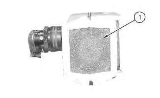
1.Removefoamfilter(1).Discardfoamfilter(1).Anewfoamfilterisprovidedinthe transducerreplacementkit.
This is the sample of the manual if you need complete manual Click Here to download