DOWNLOAD LINK
For some reason if link does not work download this pdf and then click
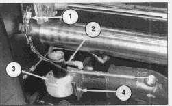
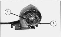
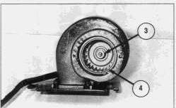
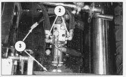
1. Remove two screws (1).
2. Remove inlet screen (2).
3. Loosen set screw (3)
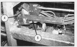
4. Remove burner blower wheel (4).
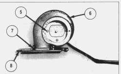
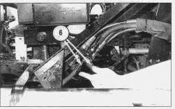
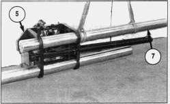
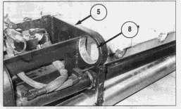
5. Remove four screws (5), and remove the burner blower motor from housing (6).
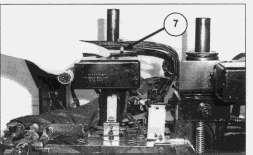
6. If necessary, remove four bolts (7) and plate (8).
NOTE: For assembly of the burner blower motor, reverse the disassembly steps.
End By:
a. install burner blower motor
Product: ASPHALT PAVER
Model: BG-2455C ASPHALT PAVER ACM
Configuration: Caterpillar AP-1055B, Barber-Greene BG-2455C Asphalt Paver ACM00001-UP (MACHINE) POWERED BY 3116 Engine
Disassembly and Assembly
8-16B,10-20B, & 10-20WB EXTEND-A-MAT SCREED
Media Number -KENR2615-00
Burner Group
SMCS - 6642-010; 6642-017
Publication Date -07/01/1996
Date Updated -03/03/2004
KENR26150010
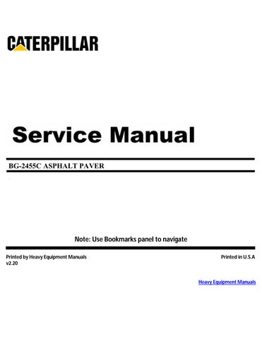
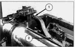
Remove & Install Burner Group
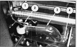
NOTE: These photos are of the left side, extender assembly burner group. The left and right side screed burner groups are the same but require the screed extender assemblies to be extended to gain access for their removal.
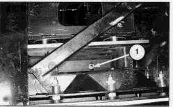
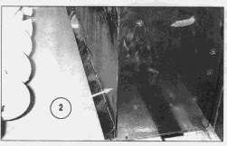
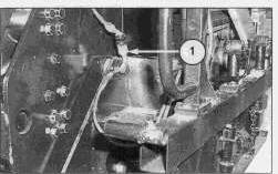
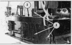
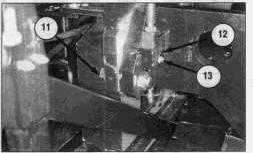
1. Cut the tie-wrap, and disconnect two electrical connections (1).
2. Disconnect fuel line (2). Cap or plug immediately.
3. Remove four bolts (4) and washers.
4. Remove assembly burner group (3).
5. Left extender assembly burner group (3) upon removal.
NOTE: For installation of the burner group, reverse the removal steps.
Disassemble & Assemble Burner Group
Start By:
a. remove burner group
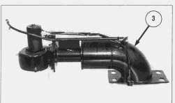
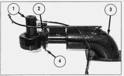
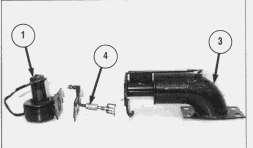
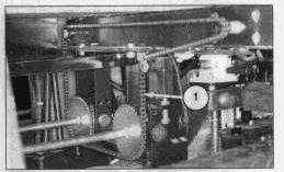
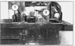
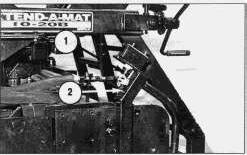
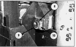
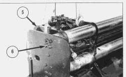
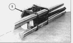
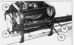
1. Remove two bolts (2), and separate blower motor assembly (1) from upper chamber assembly (3) and fuel nozzle group (4).
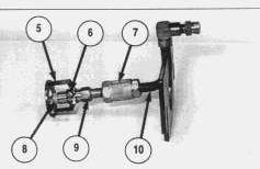
2. Disassemble fuel nozzle group (4) using the following procedure:
A. Loosen setscrew (6), and remove flame ring (5). When installing flame ring, position the flame ring 1.5 to 3.1 mm (.060 to .125 in) behind the nozzle.
B. Remove nozzle (8).
C. Remove adapter (9) from check valve (7).
D. Remove check valve (7) from pipe (10).
NOTE: For assembly of the burner group, reverse the disassembly steps.
End By:
a. install burner group
Product: ASPHALT PAVER
Model: BG-2455C ASPHALT PAVER ACM
Configuration: Caterpillar AP-1055B, Barber-Greene BG-2455C Asphalt Paver ACM00001-UP (MACHINE) POWERED BY 3116 Engine
Disassembly and Assembly
8-16B,10-20B, & 10-20WB EXTEND-A-MAT SCREED
Media Number -KENR2615-00
Publication Date -07/01/1996
Control Box Group
SMCS - 7490-010
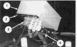
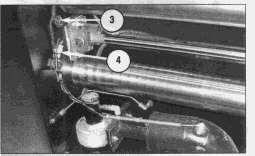
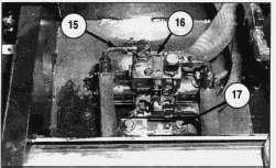
Remove & Install Control Box Group
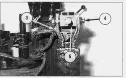
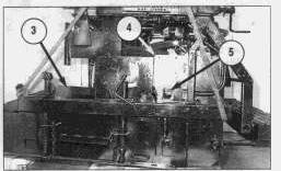
1. Disconnect four electrical connections (3).
2. Disconnect the two wires from horn (4).
3. Remove four bolts (2).
4. Remove control box group (1).
NOTE: For installation of the control box group, reverse the removal steps.
Copyright 1993 - 2024 Caterpillar Inc. All Rights Reserved.
Private Network For SIS Licensees.
Date Updated -03/03/2004
KENR26150014
Wed Oct 16 23:59:26 UTC+0530 2024
Product: ASPHALT PAVER
Model: BG-2455C ASPHALT PAVER ACM
Configuration: Caterpillar AP-1055B, Barber-Greene BG-2455C Asphalt Paver ACM00001-UP (MACHINE) POWERED BY 3116 Engine
Disassembly and Assembly
8-16B,10-20B, & 10-20WB EXTEND-A-MAT SCREED
Media Number -KENR2615-00
Publication Date -07/01/1996
Crown Chain
SMCS - 6647-010
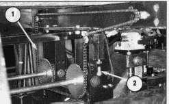
Remove & Install Crown Chain
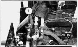
1. Loosen the tension on crown chain (1) by adjusting bolt (2).
2. Separate crown chain (1) at the master link.
3. Remove crown chain (1).
NOTE: For installation of the crown chain, reverse the removal steps.
Copyright 1993 - 2024 Caterpillar Inc. All Rights Reserved. Private Network For SIS Licensees.
Date Updated -03/03/2004
KENR26150015
Wed Oct 16 23:59:37 UTC+0530 2024
Product: ASPHALT PAVER
Model: BG-2455C ASPHALT PAVER ACM
Configuration: Caterpillar AP-1055B, Barber-Greene BG-2455C Asphalt Paver ACM00001-UP (MACHINE) POWERED BY 3116 Engine
Disassembly and Assembly
8-16B,10-20B, & 10-20WB EXTEND-A-MAT SCREED
Media Number -KENR2615-00
Publication Date -07/01/1996
Date Updated -03/03/2004
KENR26150016
Crown Group
SMCS - 6647-010
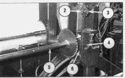
Remove & Install Crown Group
1. Release the tension on crown chain (1).
2. Find the master link on crown chain (1). Separate and remove the crown chain.
3. Remove bolt (2), the washer and sprocket (3). If necessary, remove the bushing from the sprocket.
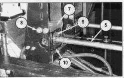
4. Remove two bolts (4) and two spacers (6) from the end of shaft assembly (5).
5. Remove four bolts (8) and bar (7). Remove shaft assembly (5) from the screed. If necessary, remove the bearings from bar (7) and the screed frame.
6. Remove trunnion (9) and yoke (10) from the shaft assembly. Remove the two bolts and spacers, and remove trunnion (9) from yoke (10).
7. Remove the locknut, and remove the two bearings, bearing block and washer from the sprocket end of the shaft assembly.
NOTE: When removing the bearings from the shaft assembly, refer to the topic "Remove & Install Thickness Control Assembly" for similar photos.
NOTE: Remove the other crown shaft assembly if necessary following the same procedure.
NOTE: For installation of the crown group, reverse the removal steps.
1993 - 2024 Caterpillar Inc.
Product: ASPHALT PAVER
Model: BG-2455C ASPHALT PAVER ACM
Configuration: Caterpillar AP-1055B, Barber-Greene BG-2455C Asphalt Paver ACM00001-UP (MACHINE) POWERED BY 3116 Engine
Disassembly and Assembly
8-16B,10-20B, & 10-20WB EXTEND-A-MAT SCREED
Media Number -KENR2615-00
Crown Group (Power)
SMCS - 6647-010
Publication Date -07/01/1996
Date Updated -03/03/2004
KENR26150017
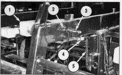
Remove & Install Crown Group (Power)
1. Release the tension on crown chain (5).
2. Find the master link on crown chain (5), separate and remove the crown chain.
3. Remove the spring pin, and remove keeper (3) and washers.
4. Remove the tie-wraps, and disconnect electrical connection (4).
5. Remove four bolts (2), nuts and washers.
6. Remove crown group (power) (1).
NOTE: For installation of the crown group (power), reverse the removal steps.
Copyright 1993 - 2024 Caterpillar Inc. All Rights Reserved. Private Network For SIS Licensees. Thu Oct 17 00:00:09 UTC+0530 2024
Product: ASPHALT PAVER
Model: BG-2455C ASPHALT PAVER ACM
Configuration: Caterpillar AP-1055B, Barber-Greene BG-2455C Asphalt Paver ACM00001-UP (MACHINE) POWERED BY 3116 Engine
Disassembly and Assembly
8-16B,10-20B, & 10-20WB EXTEND-A-MAT SCREED
Media Number -KENR2615-00
Deflector Plates
SMCS - 1151-010
Publication Date -07/01/1996
Date Updated -03/03/2004
KENR26150023
Remove & Install Deflector Plates
1. Start the engine. Extend the screed. Stop the engine.
NOTE: The right hand deflector plate overlaps the left hand deflector plate and must be removed first.
NOTE: The screed extender must be extended to allow access for removal of two of the nuts that hold the deflector plates to the main screed assembly.
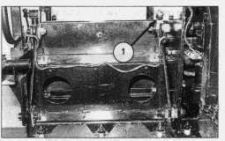
2. Remove twenty nuts (1) and washers.
3. Remove right hand and left hand deflector plate (2).
NOTE: For installation of the deflector plates, reverse the removal steps.
Copyright 1993 - 2024 Caterpillar Inc. All Rights Reserved. Private Network For SIS Licensees.
Thu Oct 17 00:01:58 UTC+0530 2024
Product: ASPHALT PAVER
Model: BG-2455C ASPHALT PAVER ACM
Configuration: Caterpillar AP-1055B, Barber-Greene BG-2455C Asphalt Paver ACM00001-UP (MACHINE) POWERED BY 3116 Engine
Disassembly and Assembly
8-16B,10-20B, & 10-20WB EXTEND-A-MAT SCREED
Media Number -KENR2615-00
Publication Date -07/01/1996
Drop Arm Bracket Assembly
SMCS - 7121-010
Remove & Install Drop Arm Bracket Assembly
Start By:
a. remove screed
Date Updated -03/03/2004
KENR26150029
1. Remove three hollow screws (1).
2. Remove cover (2).
3. Remove bolt (3) and P-clamp.
4. Remove two bolts (4).
5. Lift trunnion and shaft assembly (5) out of the way.
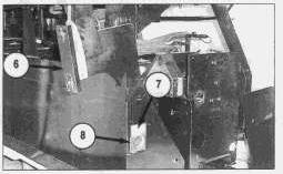
NOTE: The end gate and extension (if equipped) have been removed for photographic purposes only.
6. Attach strap and a suitable lifting device to drop arm bracket assembly (6) as shown.
7. Remove hollow screw (7).
8. Remove pivot pin assembly (8). Bolt (10) may have to be loosened to remove pivot pin assembly (8).
9. Carefully lift the bracket assembly away from the screed. The weight of the bracket assembly is 95 kg (210 lb).
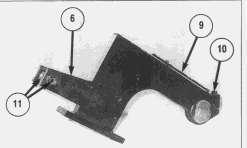
10. If necessary, remove two spacers (11) from bracket assembly (6).
11. If necessary, remove pipe assembly (9).
NOTE: For installation of the drop arm bracket assembly, reverse the removal steps.
End By:
a. install screed
Product: ASPHALT PAVER
Model: BG-2455C ASPHALT PAVER ACM
Configuration: Caterpillar AP-1055B, Barber-Greene BG-2455C Asphalt Paver ACM00001-UP (MACHINE) POWERED BY 3116 Engine
Disassembly and Assembly
8-16B,10-20B, & 10-20WB EXTEND-A-MAT SCREED
Media Number -KENR2615-00
Publication Date -07/01/1996
End Gate (With Extension)
SMCS - 6641-010
Remove & Install End Gate (With Extension)
Date Updated -03/03/2004
KENR26150018
Extension (1.0 ft) Extension (2.4 ft)
1. Disconnect electrical connection (1) to the end gate controller. Disconnect the wiring harness from the clips and reposition on the extender assembly.
2. Attach straps and a suitable lifting device to end gate (2).
3. Remove three bolts (3), nuts and washers.
4. Carefully move end gate (2) away from the screed. The weight of the end gate is 109 kg (240 lb).
NOTE: For installation of the end gate (with extension), reverse the removal steps.
Copyright 1993 - 2024 Caterpillar Inc. All Rights Reserved. Private Network For SIS Licensees.
Product: ASPHALT PAVER
Model: BG-2455C ASPHALT PAVER ACM
Configuration: Caterpillar AP-1055B, Barber-Greene BG-2455C Asphalt Paver ACM00001-UP (MACHINE) POWERED BY 3116 Engine
Disassembly and Assembly
8-16B,10-20B, & 10-20WB EXTEND-A-MAT SCREED
Media Number -KENR2615-00
Publication Date -07/01/1996
End Gate (Without Extension)
SMCS - 6641-010
Remove & Install End Gate (Without Extension)
1. Remove bolt (2) and P-clamp.
2. Disconnect electrical connection (1).
3. Attach straps and a suitable lifting device to end gate (3) as shown.
4. Remove three bolts (5), nuts and washers.
Date Updated -03/03/2004
KENR26150021
5. Lift the end gate up and away from screed (4). The weight of the end gate is 109 kg (240 lb).
NOTE: For installation of the end gate, reverse the removal steps.
Copyright 1993 - 2024 Caterpillar Inc. All Rights Reserved. Private Network For SIS Licensees. Thu Oct 17 00:01:29 UTC+0530 2024
Product: ASPHALT PAVER
Model: BG-2455C ASPHALT PAVER ACM
Configuration: Caterpillar AP-1055B, Barber-Greene BG-2455C Asphalt Paver ACM00001-UP (MACHINE) POWERED BY 3116 Engine
Disassembly and Assembly
8-16B,10-20B, & 10-20WB EXTEND-A-MAT SCREED
Media Number -KENR2615-00
Extender
SMCS - 6641-010; 6641-017
Publication Date -07/01/1996
Date Updated -03/03/2004
KENR26150001
Remove & Install Extender
NOTE: The positioning of vibrator, extender and fuel hoses should be noted before any of the Remove & Install procedures are begun. During installation, care should be taken to position the hoses to the original position.
Start By:
a. remove platform assembly
1. Disconnect two hose assemblies (1). Cap or plug immediately.
2. Disconnect two hose assemblies (2). Cap or plug immediately.
3. Disconnect four electrical connections (3).
4. Remove four bolts (4) and washers.
5. Lift up cover plate (5) to gain access to the hose assemblies.
6. Disconnect two hose assemblies (6). Cap or plug immediately.
7. Cut tie-wrap (7).
8. Bend tab down on bearing lockwasher (8).
9. Remove bearing locknut (9), bearing lockwasher (8) and bearing locknut (10).
10. Remove bolt (11), nut and washer.
11. Remove bolt (13) and washer.
12. Remove pin (12).
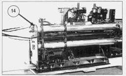
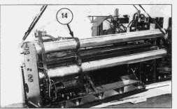
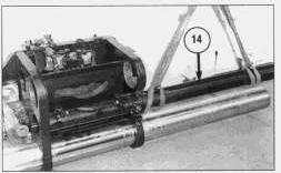
13. Attach a strap and a lift truck to extender (14) as shown. Pull the extender to the left approximately three feet.
14. Reattach the straps and a suitable lifting device to extender (14) as shown.
15. Lift the extender slowly and carefully from the screed. The weight of the extender is 657 kg (1500 lb).
NOTE: For installation of the extender, reverse the removal steps.
End By:
a. install platform assembly