


Product:ASPHALTPAVER
Model:AP-1055EASPHALTPAVERTJF
Configuration:AP1055EBG1055EAsphaltPaverTJF00001-UP(MACHINE)POWEREDBYC7.1Engine
OperationandMaintenanceManual
Topcon®SystemFive
MediaNumber-KEBU7018-12PublicationDate-01/10/2014DateUpdated-10/09/2019
Foreword
CaliforniaProposition65Warning
DieselengineexhaustandsomeofitsconstituentsareknowntotheStateofCaliforniato causecancer,birthdefects,andotherreproductiveharm.

WARNING-Thisproductcanexpose youtochemicalsincludingethylene glycol,whichisknowntotheStateof Californiatocausebirthdefectsorother reproductiveharm.Formoreinformation goto:
www.P65Warnings.ca.gov
Donotingestthischemical.Washhandsafterhandlingtoavoidincidentalingestion.
WARNING-Thisproductcanexpose youtochemicalsincludingleadandlead compounds,whichareknowntothe StateofCaliforniatocausecancer,birth defects,orotherreproductiveharm.For moreinformationgoto:
www.P65Warnings.ca.gov
Washhandsafterhandlingcomponentsthatmaycontainlead.
LiteratureInformation
Thismanualshouldbestoredintheoperator'scompartmentintheliteratureholderorseatback literaturestoragearea.
Thismanualcontainssafetyinformation,operationinstructions,transportationinformation, lubricationinformation,andmaintenanceinformation.
Somephotographsorillustrationsinthispublicationshowdetailsorattachmentsthatcanbe differentfromyourmachine.Guardsandcoversmighthavebeenremovedforillustrative purposes.
Continuingimprovementandadvancementofproductdesignmighthavecausedchangestoyour machinewhicharenotincludedinthispublication.Read,study,andkeepthismanualwiththe machine.
Wheneveraquestionarisesregardingyourmachine,orthispublication,pleaseconsultyourCat dealerforthelatestavailableinformation.
Safety
Thesafetysectionlistsbasicsafetyprecautions.Inaddition,thissectionidentifiesthetextand locationsofwarningsignsandlabelsusedonthemachine.
Readandunderstandthebasicprecautionslistedinthesafetysectionbeforeoperatingor performinglubrication,maintenance,andrepaironthismachine.
Operation
Theoperationsectionisareferenceforthenewoperatorandarefresherfortheexperienced operator.Thissectionincludesadiscussionofgauges,switches,machinecontrols,attachment controls,transportation,andtowinginformation.
Photographsandillustrationsguidetheoperatorthroughcorrectproceduresofchecking,starting, operating,andstoppingthemachine.
Operatingtechniquesoutlinedinthispublicationarebasic.Skillandtechniquesdevelopasthe operatorgainsknowledgeofthemachineanditscapabilities.
Maintenance
Themaintenancesectionisaguidetoequipmentcare.TheMaintenanceIntervalSchedule(MIS) liststheitemstobemaintainedataspecificserviceinterval.Itemswithoutspecificintervalsare listedunderthe"WhenRequired"serviceinterval.TheMaintenanceIntervalScheduleliststhe pagenumberforthestep-by-stepinstructionsrequiredtoaccomplishthescheduledmaintenance. UsetheMaintenanceIntervalScheduleasanindexor"onesafesource"forallmaintenance procedures.
MaintenanceIntervals
Usetheservicehourmetertodetermineservicingintervals.Calendarintervalsshown(daily, weekly,monthly,etc.)canbeusedinsteadofservicehourmeterintervalsifthecalendarintervals
providemoreconvenientservicingschedulesandapproximatetheindicatedservicehourmeter reading.Performtherecommendedserviceattheintervalthatoccursfirst.
Undersevere,dusty,orwetoperatingconditions,morefrequentlubricationthanisspecifiedinthe maintenanceintervalschartmightbenecessary.
Performserviceonitemsatmultiplesoftheoriginalrequirement.Forexample,atevery500 servicehoursor3months,alsoservicethoseitemslistedunderevery250servicehoursor monthlyandevery10servicehoursordaily.
CertifiedEngineMaintenance
Propermaintenanceandrepairareessentialtokeeptheengineandmachinesystemsoperating correctly.Astheheavy-dutyoff-roaddieselengineowner,youareresponsibleforthe performanceoftherequiredmaintenancelistedintheOwnerManual,OperationandMaintenance Manual,andServiceManual.
Itisprohibitedforanypersonengagedinthebusinessofrepairing,servicing,selling,leasing,or tradingenginesormachinestoremove,alter,ortorenderinoperative,anyemission-relateddevice orelementofdesigninstalledonorinanengineormachinethatisincompliancewithall applicableregulationsoftheintendedcountrytowhichithasbeenshipped.Certainelementsof themachineandenginesuchastheexhaustsystem,fuelsystem,electricalsystem,intakeair system,andcoolingsystemmaybeemission-relatedandshouldnotbealteredunlessapprovedby Caterpillar.
MachineCapacity
Additionalattachmentsormodificationsmayexceedmachinedesigncapacitywhichcan adverselyaffectperformancecharacteristics.Includedwouldbestabilityandsystemcertifications suchasbrakes,steering,androlloverprotectivestructures(ROPS).ContactyourCatdealerfor furtherinformation.
ProductIdentificationNumber
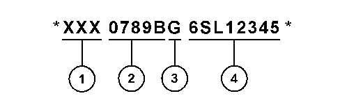
EffectiveFirstQuarter2001theProductIdentificationNumber(PIN)haschangedfrom8to17 characters.Toprovideuniformequipmentidentification,constructionequipmentmanufacturers aremovingtocomplywiththelatestversionoftheproductidentificationnumberingstandard. Non-roadmachinePINsaredefinedbyISO10261.ThenewPINformatwillapplytoall machinesandgeneratorsets.ThePINplatesandframemarkingwilldisplaythe17characterPIN. Thenewformatwilllooklikethefollowing:
This is the sample of the manual if you need complete manual Click Here to download
Where:
1.WorldManufacturingCode(characters1-3)
2.MachineDescriptor(characters4-8)
3.CheckCharacter(character9)
4.MachineIndicatorSection(MIS)orProductSequenceNumber(characters10-17).Thesewere previouslyreferredtoastheSerialNumber.
MachinesandgeneratorsetsproducedbeforeFirstQuarter2001willmaintaintheir8character PINformat.
Componentssuchasengines,transmissions,axles,andworktoolswillcontinuetousean8 characterSerialNumber(S/N).
Copyright1993-2023CaterpillarInc. AllRightsReserved. PrivateNetworkForSISLicensees.
ThuMay2522:41:56UTC+05302023
Product:ASPHALTPAVER
Model:AP-1055EASPHALTPAVERTJF
Configuration:AP1055EBG1055EAsphaltPaverTJF00001-UP(MACHINE)POWEREDBYC7.1Engine
OperationandMaintenanceManual
MediaNumber-KEBU7018-12PublicationDate-01/10/2014DateUpdated-10/09/2019 i01573736
Components-Clean/Inspect
SMCS-7220-040;7220-070;7220-571
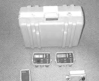
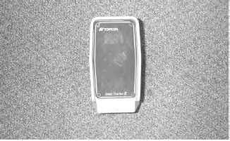
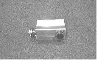
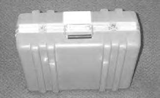
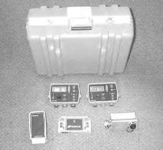
Keepthecarryingcasedryandstorethecarryingcaseinadry location.Neverletthecarryingcasebecomewet.Ifthecasebecomes wet,removethecomponentsandairuntildry.Moistureinthe componentscancausecorrosionresultinginequipmentfailure.
WipetheTopcon®SystemFivecomponentsandcleantheTopcon®SystemFiveattheendofthe day.Placethecomponentsandthecoilcordsintheappropriatesectionsofthecarryingcasefor storage.Thiswillensuretheintegrityofthesecomponentsandproperstoragewillprotectthe componentsfromvandalismortheft.
Copyright1993-2023CaterpillarInc. AllRightsReserved. PrivateNetworkForSISLicensees.
ThuMay2522:50:10UTC+05302023
Product:ASPHALTPAVER
Model:AP-1055EASPHALTPAVERTJF
Configuration:AP1055EBG1055EAsphaltPaverTJF00001-UP(MACHINE)POWEREDBYC7.1Engine
OperationandMaintenanceManual Topcon®SystemFive
MediaNumber-KEBU7018-12PublicationDate-01/10/2014DateUpdated-10/09/2019 i05959475
MaintenanceIntervalSchedule
SMCS-7000;7220
WhenRequired
Transducer-Clean/Inspect Transducer-Replace
Every10ServiceHoursorDaily
Components-Clean/Inspect
Every1000ServiceHoursor1Year
Transducer-Replace
Copyright1993-2023CaterpillarInc. AllRightsReserved. PrivateNetworkForSISLicensees.
ThuMay2522:49:43UTC+05302023
Product:ASPHALTPAVER
Model:AP-1055EASPHALTPAVERTJF
Configuration:AP1055EBG1055EAsphaltPaverTJF00001-UP(MACHINE)POWEREDBYC7.1Engine
OperationandMaintenanceManual
Topcon®SystemFive
MediaNumber-KEBU7018-12PublicationDate-01/10/2014DateUpdated-10/09/2019
Transducer-Clean/Inspect
SMCS-1904-571;7220-571
i02457225
Note:Thisprocedureisnotmeanttobearegularmaintenanceprocedure.Cleanthetransducer onlywhencontaminationissuspectedorcontaminationisevident.
Note:Cleaningthetransducertoomuchwillshortenthelifeofthetransducer.Cleaningthe transducertoomuchmayalsodamagethesonicdetectionunit.
UsethefollowingproceduretocleantheSonicTrackerII®Transducer.
1.Holdthesonicdetectionunitinanuprightpositioninordertopreventmoisturefrom inadvertentlyenteringthesonicdetectionunit.
2.Mixamilddetergentwithwaterandplacethesolutioninasquirtbottle.
Note:CaterpillarrecommendstheuseofSimpleGreen®detergent.
3.Whileyouholdthesonicdetectionunitupright,thoroughlyspraythetransducerwiththe solution.
4.Aftersprayingthetransducerwiththesolution,fillthesquirtbottlewithcleanwater.Rinse offanyresidualdetergentonthetransducer.
5.Allowthesonicdetectionunittothoroughlydry.
Copyright1993-2023CaterpillarInc. AllRightsReserved. PrivateNetworkForSISLicensees.
ThuMay2522:50:23UTC+05302023
Product:ASPHALTPAVER
Model:AP-1055EASPHALTPAVERTJF
Configuration:AP1055EBG1055EAsphaltPaverTJF00001-UP(MACHINE)POWEREDBYC7.1Engine
OperationandMaintenanceManual
MediaNumber-KEBU7018-12PublicationDate-01/10/2014DateUpdated-10/09/2019
Transducer-Replace
SMCS-7220-510-KIT
i01573743
Note:IftheSonicTrackerII®isexperiencingerraticreadingsorinconsistentreadings, contaminationofthetransducershouldbeconsideredfirstbeforeyouassumeanyothertypeof failure.Themostcommonwarningsignofcontaminationinthetransduceristheabilityofthe SonicTrackerII®toseetheground,butnotastringline.
Theonlytoolsthatareneededforthisprocedureareacrosstipscrewdriverandasmallpairof cutters.Thetransducercanbereplacedwiththefollowingprocedure:
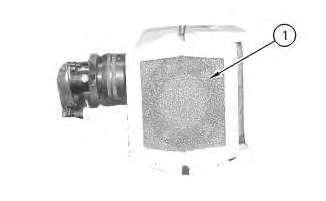
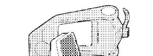
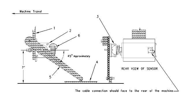
1.Removefoamfilter(1).Discardfoamfilter(1).Anewfoamfilterisprovidedinthe transducerreplacementkit.
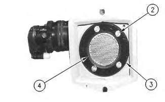
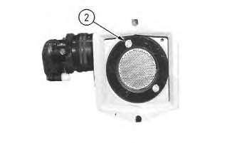
2.Removefourscrews(2).ThescrewssecuretheblackretainingringtotheSonic®Tracker II.Removeretainingring(3).RemoveO-ring(4).DiscardO-ring(4).AnewO-ringis suppliedwiththetransducerReplacementKit.
Note:Fourreplacementscrewsaresuppliedinthetransducerreplacementkit.Trytouse theoriginalscrews.Keepthefourscrewsthataresuppliedinthetransducerkit.Theextra screwscanbeusedifyouloseanyofthescrews.
Note:AlwaysremovetheusedO-rings.AlwaysdiscardtheusedO-rings.TheusedO-rings mayloseflexibility.TheO-ringsmaybecomedistorted.Thisisaresultofweather conditionsorthisisaresultofexposuretodieselfumes. Illustration3g00824333
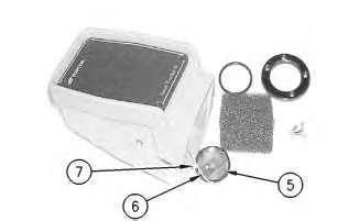
3.Transducer(5)cannowbepulledout.Removethetransducergently.
Togentlycutty-wrap(6),useasmallpairofwirecutters.Thenremovethesmallwire connectorsfromtabs(7).
Note:Whenyoucutthety-wrap,becarefulnottocutthewiresordamagethewires.
This is the sample of the manual if you need complete manual Click Here to download
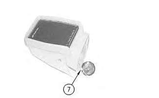
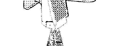
4.Placethewireconnectorsofthenewtransducerfirmlyontabs(7).Thegraywireconnector isplacedontheelevatedtab.Placethety-wrapintheslotnexttotheelevatedgraywiretab. Tightenthety-wrapandtrimthety-wrap.Becarefulnottopinchthewires.
5.PlacethenewO-ringaroundthetransducer.FeedthewiresupwardintotheSonicTracker II®.Seatthenewtransducergentlyintotherecessedarea.Thetwowiretabsmustsitinto theextradeepareaoftherecess.SeattheO-ringfirmlybetweenthetransducerandthe SonicTrackerII®.
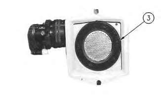
Illustration5g00825725
6.Placeblackretainingring(3)overthetransducerassembly.Makesurethatthebeveled edgesontheretainingringareout.Theflatsurfaceoftheretainingringshouldseatagainst thebaseoftheSonicTrackerII®.Lineuptheholesforthemountingscrews.Themounting screwholesaresettoanirregularpattern.Thisensuresthattheretainingringwillonlyline upwiththemountingholesinoneway.
7.Startmountingscrews(2)intotheholes.Handtighteneachscrewuntilthescrewsbecome firm.Donotovertightenthescrews.Useacrosspatterninordertotightenthescrews.
Note:Ifyouovertightenthescrews,adistortionofthemetallicmaterialonthetransducer mayoccur.Also,theretainingringmaycrack.UseoftheO-ringensurestightness.Useof theO-ringalsopreventsvibrationsfromlooseningthemountingscrews.
Note:Donotuseretainingcompoundonthemountingscrews.Retainingcompoundwill corrodetheplasticretainingring.
8.Makesurethatyouobservenowrinklesinthemetallicsurfaceinsidethetransducer.If distortionisevident,repeatSteps5through8.
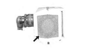
Illustration7g00826045
9.Placenewfoamfilteroverthetransducer.TheSonicTrackerII®isnowreadytoreturnto operation.
Copyright1993-2023CaterpillarInc. AllRightsReserved. PrivateNetworkForSISLicensees.
ThuMay2522:50:44UTC+05302023
Product:ASPHALTPAVER
Model:AP-1055EASPHALTPAVERTJF
Configuration:AP1055EBG1055EAsphaltPaverTJF00001-UP(MACHINE)POWEREDBYC7.1Engine
OperationandMaintenanceManual Topcon®SystemFive
MediaNumber-KEBU7018-12PublicationDate-01/10/2014DateUpdated-10/09/2019 i01573262
AccessingTheMenu
SMCS-7000;7220
Thefollowinginformationexplainstheproceduresinordertoaccesstheoperatorsmenu.
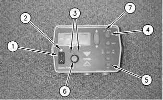
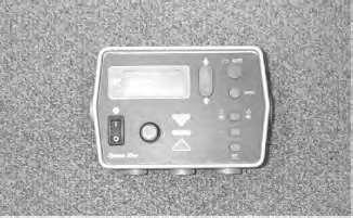
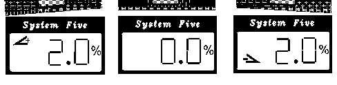
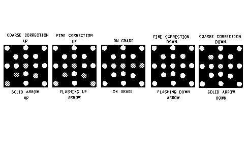
Illustration1g00817289
(1)Powerswitch
(2)LightsensorfortheLEDdisplay
(3)Gradeadjustmentarrows
(4)Auto/manualbutton
(5)Set/menubutton
(6)Gradeadjustmentknob
(7)Autolight
1.Turnpowerswitch(1)totheONposition.
Whileyouholdset/menubutton(5)down,turnthepowertotheboxtotheOFFposition andthenbacktotheONposition.Autolight(7)andthegradeadjustmentarrows(3)will flash.
2.Rotategradeadjustmentknob(6)inordertoscrollthroughtheperformancemenu selections.See"Table1".
UNITuntIn.in,ft,cm
BeeperAlarmbEPONON/OFF
TestTSTNoSettingopen,short,pass
3.TheoperatorsmenuwillgivetheoperatoraccesstothePerformance/TechniciansMenu. Turngradeadjustmentknob(6)untilthe"BEEPER"selectionismade.
4.Pressauto/manualbutton(4).Holdthebuttondownwardforapproximately15seconds.
5.Oncethecontrolboxhasenteredthemenu,theredarrowsongradeadjustmentknob(6) willflash.Turnthegradeadjustmentknob.Themenusettingswillbedisplayed.
Copyright1993-2023CaterpillarInc. AllRightsReserved. PrivateNetworkForSISLicensees.
ThuMay2522:48:56UTC+05302023
Product:ASPHALTPAVER
Model:AP-1055EASPHALTPAVERTJF
Configuration:AP1055EBG1055EAsphaltPaverTJF00001-UP(MACHINE)POWEREDBYC7.1Engine
OperationandMaintenanceManual
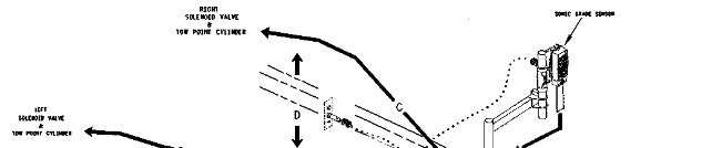
ComponentDescriptions
SMCS-7000;7220
i02385553
TheTopconSystemFiveisacompletenon-contactingcontrolsystem(Option1)oracontacting controlsystem(Option2).Thesystemisacombinationofelevationcontrolsandslopecontrols.The systemincludesthefollowingcomponents:twocontrolboxes,twoSonicTrackerIIunits(Option1), twocontactsensors(Option2)andasingleslopesensor.AcombinationofoneSonicTrackerIIand onecontactsensormaybepurchasedwiththeTopconSystemFive.Thecontrolboxesontheright sideofthemachineandontheleftsideofthemachinecontroleachrespectiveside.Theslopeorthe elevationiscontrolledbytherespectiveside.TheprimaryfunctionoftheTopconSystemFiveis providingscreedcontrol.Thiswillplacethepavingmaterialatthecorrectelevationandthecorrect slope.