


Note: Use Bookmarks panel to navigate

Product: WHEEL LOADER
Model: 982M WHEEL LOADER LRS
Configuration: 982M Wheel Loader LRS00001-UP (MACHINE) POWERED BY C13 Engine
Disassembly and Assembly
980M T3 and 982M T3 Wheel Loader Engine Supplement
Engine Oil Pump - Remove and Install
SMCS - 1304-010; 1315-010
Removal Procedure Table 1
Required Tools
1. Refer to Operation and Maintenance Manual, "Cooling System Coolant (ELC) - Change" for the correct draining and filling procedures.
2. Open the hood and remove the left side engine panel.
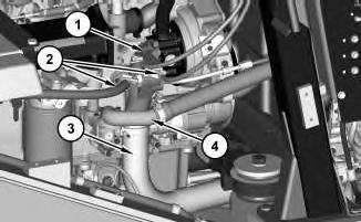
Illustration 1
3. Remove hose assemblies (2).
This is the sample of the manual click on the download link for complete manual
DOWNLOAD LINK
For some reason if link does not work download this pdf and then click
4. Remove filler tube assembly (4). Remove elbow assembly (1) position and tube assembly (3) out of the way.
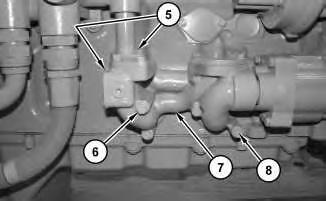
Illustration 2
5. Remove bolts (5) and bolts (8). Remove manifold (6) and couplings (7).
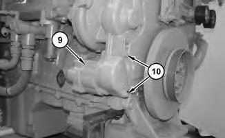
Illustration 3
6. Remove bolts (10) and engine oil pump (9).
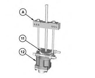
Illustration 4
g02517637
7. Use Tooling (A) to remove gear (11) from engine oil pump (12).
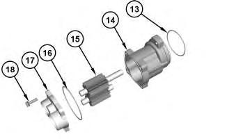
Illustration 5
g02517639
8. Remove O-ring seal (13) from body (14). Remove bolts (18), cover (17), and O-ring seal (16).
9. Remove shaft assemblies (15) from body (14).
Installation Procedure
Note: Lubricate all O-ring seals and bores during installation with the lubricant that is being sealed.
1. Install engine oil pump (9) in the reverse order of removal.
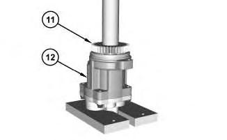
Illustration 6
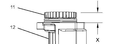

Illustration 7
g02517659
a. Use a suitable press to install gear (11) onto engine oil pump (12). Install gear (11) to Dimension (X). Dimension (X) is 29.4 ± 0.5 mm (1.16 ± 0.02 inch).
Copyright 1993 - 2024 Caterpillar Inc. All Rights Reserved. Private Network For SIS Licensees. Thu Jul 11 15:36:05 UTC+0530 2024
Product: WHEEL LOADER
Model: 982M WHEEL LOADER LRS
Configuration: 982M Wheel Loader LRS00001-UP (MACHINE) POWERED BY C13 Engine
Disassembly and Assembly
980M T3 and 982M T3 Wheel Loader Engine Supplement
Media Number -M0075590-00 Publication Date -01/11/2016 Date Updated -07/11/2016
Engine Oil Pan - Remove and Install
SMCS - 1302-010
Removal Procedure
Start By:
a. Remove the crankcase guard.
b. Remove fuel tank.
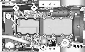
Illustration 1
Bottom view of the machine.
g02517377
1. Disconnect the harness assembly from switch (4). Remove switch (4).
2. Remove bolts (1) and stud bolts (2). Remove oil pan (3) and discard the gasket.
i05294903
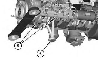
3. Remove bolts (5) and remove suction bell (6). Remove the elbow from suction bell (6).
Installation Procedure
1. Install oil pan (3) in the reverse order of removal.
a. Tighten switch (4) to a torque of 60 ± 13 N·m (44 ± 10 lb ft).
Copyright 1993 - 2024 Caterpillar Inc. All Rights Reserved. Private Network For SIS Licensees. Thu Jul 11 15:35:56 UTC+0530 2024
Product: WHEEL LOADER
Model: 982M WHEEL LOADER LRS
Configuration: 982M Wheel Loader LRS00001-UP (MACHINE) POWERED BY C13 Engine
Disassembly and Assembly
980M T3 and 982M T3 Wheel Loader Engine Supplement
Media Number -M0075590-00 Publication Date -01/11/2016 Date Updated -07/11/2016
Engine, Torque Converter, Transmission and Output
Transfer Gears - Install
SMCS - 1006-012
Installation Procedure Table 1 Required Tools
Tool Part Number Part Description Qty A 369-5916 Link Bracket 4
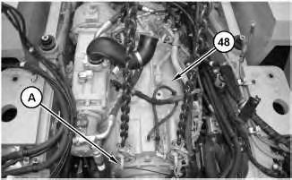
Illustration 1
2
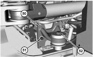
Illustration 3
g06131402
1. Attach Tooling (A) and a suitable lifting device to engine and transmission (48). The weight of engine and transmission (48) is approximately 1315 kg (2899 lb). Install engine and transmission (51).
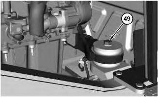
2. Install bolts (49). Tighten bolts (49) to a torque of 900 ± 100 N·m (664 ± 74 lb ft). Repeat for the opposite side.
3. Install mounting assembly (50) and bolts (51). Install bolts (52). Tighten bolts (52) to a torque of 900 ± 100 N·m (664 ± 74 lb ft). Repeat for the opposite side.
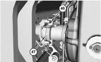
Illustration 4
g06131259
4. Install joint (47) and bolts (46). Tighten bolts (46) to a torque of 150 ± 15 N·m (111 ± 11 lb ft).
5
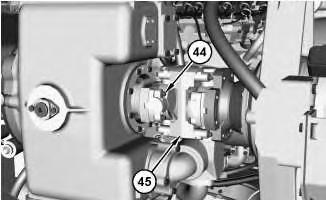
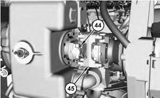
5. Install joint (45) and bolts (44). Tighten bolts (44) to a torque of 150 ± 15 N·m (111 ± 11 lb ft).
6
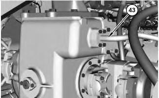
6. Connect tube assembly (43).
7
7.
8
9
10
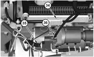
11. Connect harness assemblies (36), (35), and (34).
12
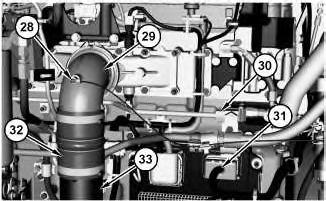
12. Connect harness assembly (31) and hose assembly (30).
13. Connect tube assembly (29). Tighten the clamp of tube assembly (29) to a torque of 8.5 ± 1 N·m (75 ± 9 lb in). Connect hose assembly (28).
14. Connect tube assembly (33) and hose assembly (32).
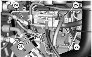
15. Connect tube assembly (27).
16. Connect hose assemblies (26), (25), and (24).
14
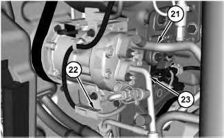
17. Connect harness assembly (22).
18. Connect tube assemblies (23) and (21).
15
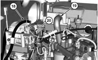
19. Connect hose assembly (19).
20. Connect harness assemblies (20) and (18).
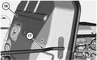
Illustration 16
21. Install engine shield (16) and support assembly (17).
17
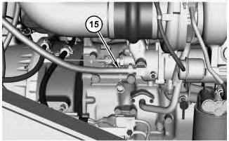
22. Connect hose assembly (15).
18
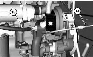
23. Connect hose assemblies (14) and (13).
19
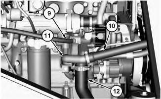
24. Install tube assembly (11).
25. Connect hose assemblies (10) and (9).
26. Connect hose assembly (12). Tighten the clamp of hose assembly (12) to a torque of 10 ± 1 N·m (89 ± 9 lb in).
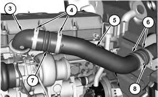
Illustration 20
27. Install hose (8) and clamps (6).
g06131161
28. Install tube assembly (3). Tighten the clamp of tube assembly (3) to a torque of 8.5 ± 1 N·m (75 ± 9 lb in).
29. Install hose (7) and clamps (4).
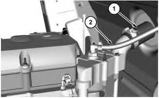
Illustration 21
g06131159
30. Connect hose assemblies (2) and (1). Tighten the clamp of hose assembly (1) to a torque of 10 ± 1 N·m (89 ± 9 lb in).
End By:
a. Install the steering valve.
b. Install the power train guard.
c. Install the exhaust elbow.
d. Install the hydraulic tank.
e. Install the air cleaner.
f. Install the muffler.
Copyright 1993 - 2024 Caterpillar Inc. All Rights Reserved. Private Network For SIS Licensees.
Thu Jul 11 15:35:44 UTC+0530 2024
Product: WHEEL LOADER
Model: 982M WHEEL LOADER LRS
Configuration: 982M Wheel Loader LRS00001-UP (MACHINE) POWERED BY C13 Engine
Disassembly and Assembly
980M T3 and 982M T3 Wheel Loader Engine Supplement
Media Number -M0075590-00 Publication Date -01/11/2016 Date Updated -07/11/2016
Engine, Torque Converter, Transmission and Output
Transfer Gears - Remove
SMCS - 1006-011
Removal Procedure
Table 1
Required Tools
Tool
A 369-5916 Link Bracket 4
Start By:
a. Remove the muffler.
b. Remove the air cleaner.
c. Remove the hydraulic tank.
d. Remove the exhaust elbow.
e. Remove the power train guard.
f. Remove the steering valve.
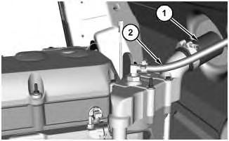
1
1. Disconnect hose assemblies (1) and (2).
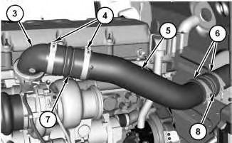
2
2. Remove tube assembly (3). Loosen clamps (4) and remove hose (7).
3. Remove tube assembly (5). Loosen clamps (6) and remove hose (8).
3
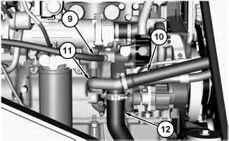
4. Disconnect hose assemblies (9), (10), and (12).
5. Remove tube assembly (11).
4
6. Disconnect hose assemblies (13) and (14).
5
7. Disconnect hose assembly (15).
6
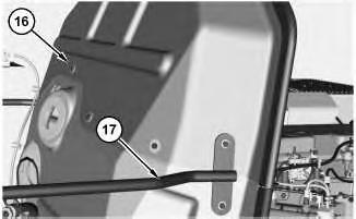
8. Remove support assembly (17) and engine shield (16).
7
9. Disconnect harness assemblies (18) and (20).
10. Disconnect hose assembly (19).
Illustration 8
11. Disconnect tube assemblies (21) and (23).
g06131203
12. Disconnect harness assembly (22).
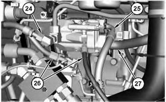
Illustration 9
g06131206
13. Disconnect hose assemblies (24), (25), and (26).
14. Disconnect tube assembly (27).
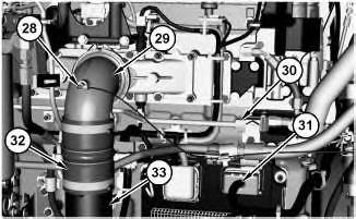
15. Disconnect hose assembly (28) and tube assembly (29).
16. Disconnect hose assembly (32) and tube assembly (33).
17. Disconnect hose assembly (30) and harness assembly (31).
18. Disconnect harness assemblies (34), (35), and (36).
12
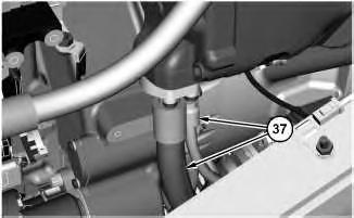
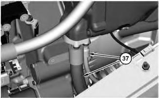
19. Disconnect hose assemblies (37).
13
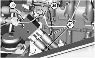
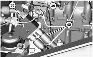
20. Disconnect harness assembly (39) and hose assembly (40). Remove manifold (38).
14
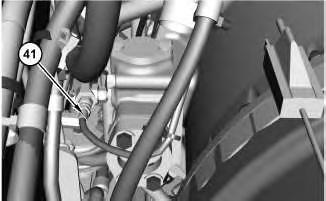
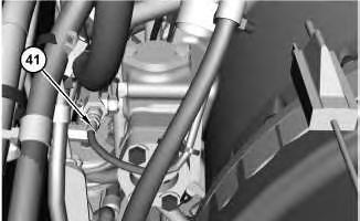
21. Disconnect hose assembly (41).
15
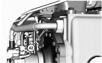
22. Disconnect tube assembly (42).
16
17
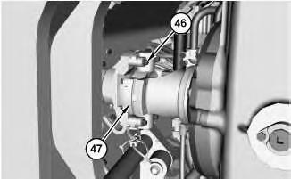
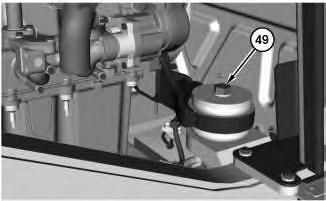
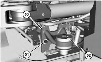
26. Attach Tooling (A) and a suitable lifting device to engine and transmission (48). The weight of engine and transmission (48) is approximately 1315 kg (2899 lb).
27. Remove bolts (49). Repeat for the opposite side.
28. Remove bolts (52). Remove bolts (51) and mounting assembly (50). Repeat for the opposite side.
29. Remove engine and transmission (48). Copyright 1993 - 2024 Caterpillar Inc.
Rights Reserved.
Network For SIS Licensees. Thu Jul 11 15:35:29 UTC+0530 2024
Product: WHEEL LOADER
Model: 982M WHEEL LOADER LRS
Configuration: 982M Wheel Loader LRS00001-UP (MACHINE) POWERED BY C13 Engine
Disassembly and Assembly
980M T3 and 982M T3 Wheel Loader Engine Supplement
Refrigerant Condenser - Remove and Install
SMCS - 1805-010
Removal Procedure Table 1
Personal injury can result from contact with refrigerant.
This system is under pressure at all times, even if the engine is not running. Heat should never be applied to a charged system.
Contact with refrigerant can cause frost bite. Keep face and hands away to help prevent injury.
Protective goggles must always be worn when refrigerant lines are opened, even if the gauges indicate the system is empty of refrigerant.
Always use caution when a fitting is removed. Slowly loosen the fitting. If the system is still under pressure, evacuate the system recovering the refrigerant before removing the fitting.
Personal injury or death can result from inhaling refrigerant through a lit cigarette.
This is the sample of the manual click on the download link for complete manual
DOWNLOAD LINK
For some reason if link does not work download this pdf and then click