



Product: WHEEL LOADER
Model: 980M WHEEL LOADER KRS
Configuration: 980M Wheel Loader KRS00001-UP (MACHINE) POWERED BY C13 Engine
Operation and Maintenance Manual
980M and 982M Wheel
Loaders
Foreword
SMCS - 4490; 7000; 7008; 7490; 7602; 7606; 7620; 7631
Literature Information
This manual should be stored in the operator's compartment in the literature holder or seat back literature storage area.
This manual contains safety information, operation instructions, transportation information, lubrication information and maintenance information.
Some photographs or illustrations in this publication show details or attachments that can be different from your machine. Guards and covers might have been removed for illustrative purposes.
Continuing improvement and advancement of product design might have caused changes to your machine which are not included in this publication. Read, study and keep this manual with the machine.
Whenever a question arises regarding your machine, or this publication, please consult your Cat dealer for the latest available information.
Safety
The safety section lists basic safety precautions. In addition, this section identifies the text and locations of warning signs and labels used on the machine.
Read and understand the basic precautions listed in the safety section before operating or performing lubrication, maintenance and repair on this machine.
Operation
The operation section is a reference for the new operator and a refresher for the experienced operator. This section includes a discussion of gauges, switches, machine controls, attachment controls, transportation and towing information.
Photographs and illustrations guide the operator through correct procedures of checking, starting, operating and stopping the machine.
Operating techniques outlined in this publication are basic. Skill and techniques develop as the operator gains knowledge of the machine and its capabilities.
Maintenance
The maintenance section is a guide to equipment care. The Maintenance Interval Schedule (MIS) lists the items to be maintained at a specific service interval. Items without specific intervals are listed under the "When Required" service interval. The Maintenance Interval Schedule lists the page number for the step-by-step instructions required to accomplish the scheduled maintenance. Use the Maintenance Interval Schedule as an index or "one safe source" for all maintenance procedures.
Maintenance Intervals
Use the service hour meter to determine servicing intervals. Calendar intervals shown (daily, weekly, monthly, etc.) can be used instead of service hour meter intervals if they provide more convenient servicing schedules and approximate the indicated service hour meter reading. Recommended service should always be performed at the interval that occurs first.
Under extremely severe, dusty or wet operating conditions, more frequent lubrication than is specified in the maintenance intervals chart might be necessary.
Perform service on items at multiples of the original requirement. For example, at every 500 service hours or 3 months, also service those items listed under every 250 service hours or monthly and every 10 service hours or daily.
California Proposition 65 Warning
Diesel engine exhaust and some of its constituents are known to the State of California to cause cancer, birth defects, and other reproductive harm.
Battery posts, terminals and related accessories contain lead and lead compounds. Wash hands after handling.
Certified Engine Maintenance
Proper maintenance and repair is essential to keep the engine and machine systems operating correctly. As the heavy duty off-road diesel engine owner, you are responsible for the performance of the required maintenance listed in the Owner Manual, Operation and Maintenance Manual, and Service Manual.
It is prohibited for any person engaged in the business of repairing, servicing, selling, leasing, or trading engines or machines to remove, alter, or render inoperative any emission related device or element of design installed on or in an engine or machine that is in compliance with the regulations (40 CFR Part 89). Certain elements of the machine and engine such as the exhaust system, fuel system, electrical system, intake air system and cooling system may be emission related and should not be altered unless approved by Caterpillar.
Machine Capacity
Additional attachments or modifications may exceed machine design capacity which can adversely affect performance characteristics. Included would be stability and system certifications such as brakes, steering, and rollover protective structures (ROPS). Contact your Cat dealer for further information.
Cat Product Identification Number
Effective First Quarter 2001 the Cat Product Identification Number (PIN) has changed from 8 to 17 characters. In an effort to provide uniform equipment identification, Caterpillar and other construction equipment manufacturers are moving to comply with the latest version of the product identification numbering standard. Non-road machine PINs are defined by ISO 10261. The new PIN format will apply to all Cat machines and generator sets. The PIN plates and frame marking will display the 17 character PIN. The new format will look like the following:
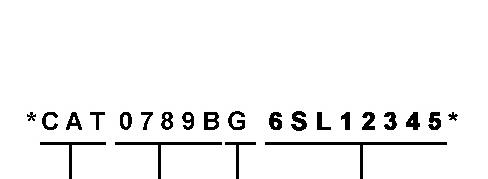
Illustration 1 g00751314
Where:
1. Caterpillar's World Manufacturing Code (characters 1-3)
This is the sample of the manual click on the download link for complete manual
DOWNLOAD LINK
For some reason if link does not work download this pdf and then click
2. Machine Descriptor (characters 4-8)
3. Check Character (character 9)
4. Machine Indicator Section (MIS) or Product Sequence Number (characters 10-17). These were previously referred to as the Serial Number.
Machines and generator sets produced before First Quarter 2001 will maintain their 8 character PIN format.
Components such as engines, transmissions, axles, etc. and work tools will continue to use an 8 character Serial Number (S/N). Copyright 1993 - 2024 Caterpillar Inc. All Rights Reserved. Private Network For SIS Licensees.

Product: WHEEL LOADER
Model: 980M WHEEL LOADER KRS
Configuration: 980M Wheel Loader KRS00001-UP (MACHINE) POWERED BY C13 Engine
Operation and Maintenance Manual
980M and 982M Wheel Loaders
Media Number -SEBU9054-13
ARD Spark Plug - Clean
SMCS - 1555-070
Date -01/02/2019 Date Updated -28/02/2019
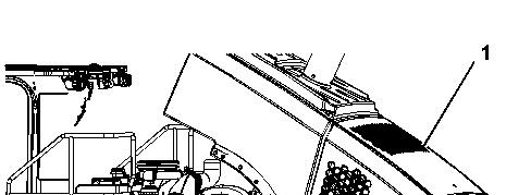
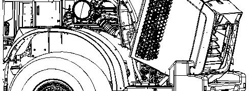

Illustration 1 g03664768 (1) Hood assembly (open)
Access to the ARD spark plug is made from behind the engine compartment on the left-hand side of the machine.
NOTICE
If the engine is running or the key is in the ON position, the ARD plug will continue to fire. Turn the key to the OFF position before servicing the ARD plug.
1. Open hood assembly (1) that is located behind the engine compartment.
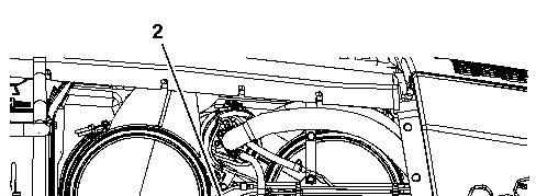
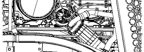

Illustration 2
Location of ARD spark plug. (2) ARD spark plug wire assembly
g03664833
2. Disconnect ARD spark plug wire assembly (3) from the ARD spark plug.
3. Use a deep well socket and a breaker bar to loosen the spark plug. If necessary, consult your Cat dealer for the part number of the socket. After the spark plug has been loosened, use the socket to remove the spark plug by hand in order to detect problems with the threads.
4. After removing spark plug, clean the ground probe inside the ARD combustion head by running a 305-2389 Plug Bore Brush through the hole in the ARD combustion head. Run the brush through the hole several times.
5. Carefully clean the spark plug using a nonmetallic cleaning pad. If the probe appears to be bent, replace the spark plug. Otherwise, install the original spark plug.
Note: The spark plug may be damaged if the spark plug is dropped. Do not install a spark plug that has been dropped.
NOTICE
Do not overtighten the spark plug. The shell can be cracked and the gasket can be deformed. The metal can deform and the gasket can be damaged. The shell can be stretched. This will loosen the seal that is between the shell and the insulator, allowing combustion pressure to blow past the seal. Serious damage to the engine can occur.
Use the proper torque.
6. Install the spark plug by hand until the spark plug contacts the ARD. Tighten the spark plug to a torque of 43.4 N·m (32 lb ft) to 51.5 N·m (38 lb ft).
7. Connect the ARD spark plug wire assembly.
8. Close the hood assembly that was opened in step 1.
Product: WHEEL LOADER
Model: 980M WHEEL LOADER KRS
Configuration: 980M Wheel Loader KRS00001-UP (MACHINE) POWERED BY C13 Engine
Operation and Maintenance Manual
980M and 982M Wheel Loaders
Media Number -SEBU9054-13
Date -01/02/2019
Articulation Bearings - Lubricate
SMCS - 7057-086-BD; 7065-086-BD; 7066-086-BD
Updated -28/02/2019
Crushing Hazard. Connect the steering frame lock between front and rear frames before servicing the machine in the articulation area. Disconnect the steering frame lock and secure it in the stored position before resuming operation. Failure to do so could result in serious injury or death.
Ensure that the machine ignition switch is in the OFF position and that the parking brake is engaged before entering the articulation area.
Refer to Operation and Maintenance Manual, "Steering Frame Lock" before entering the articulation joint.
Wipe all fittings before applying grease.
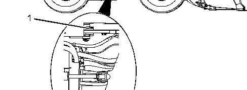

Illustration 1 g03661141
Apply grease to one fitting on the upper pivot bearing (1) and one fitting on the lower pivot bearing (2).
Copyright 1993 - 2024 Caterpillar Inc. All Rights Reserved. Private Network For SIS Licensees.
Tue Jun 25 22:21:39 UTC+0530 2024
Product: WHEEL LOADER
Model: 980M WHEEL LOADER KRS
Configuration: 980M Wheel Loader KRS00001-UP (MACHINE) POWERED BY C13 Engine
Operation and Maintenance Manual
980M and 982M Wheel Loaders
Media Number -SEBU9054-13
Date -01/02/2019
Updated -28/02/2019
Automatic Lubrication Filler Filter - Clean - Automatic TWIN Greasing System - If Equipped
SMCS - 7540-070-HR
Note: This procedure is only required on the Automatic TWIN Greasing System. This procedure is not required on the Cat Autolube.
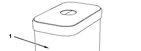
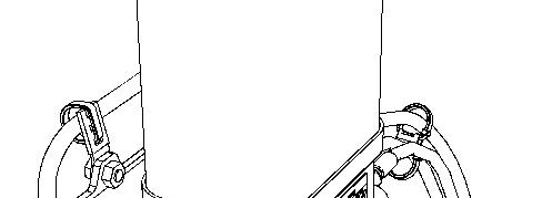
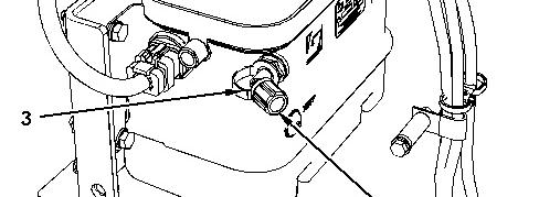

Illustration 1 g02494037
(1) Reservoir
(2) Dust Cap (3) Filler Tube Assembly
Note: Do not remove cover to fill.
1. Remove dust cap (2) from reservoir (1).
2. Clean filler tube assembly (3) and the coupling on the filler tube assembly.
3. Remove filler tube assembly (3) and the coupling.
4. Remove the grease fitting from the filter and clean the filter.
5. Clean the filter with solvent and compressed air. Check the filter for cracks. If any cracks exist, replace the filter.
6. Replace the grease fitting in the filter.
7. Fill the filter with grease.
8. Install the filter.
9. Install the filter assembly onto filler tube assembly (3).
10. Install filler tube assembly (3) and dust cap (2).
Copyright 1993 - 2024 Caterpillar Inc. All Rights Reserved. Private Network For SIS Licensees. Tue Jun 25 22:21:52 UTC+0530 2024
Product: WHEEL LOADER
Model: 980M WHEEL LOADER KRS
Configuration: 980M Wheel Loader KRS00001-UP (MACHINE) POWERED BY C13 Engine
Operation and Maintenance Manual 980M and 982M Wheel Loaders
Media Number -SEBU9054-13
Automatic Lubrication Grease Tank - Fill - Autolube - If Equipped
SMCS - 7540-544-TNK
The Automatic TWIN Greasing System
Reference: Refer to System Operation, RENR 6331 for more information on the Automatic TWIN Greasing System.
A pressure hazard is present. Severe personal injury or death can result from removing hoses or fittings that are under pressure. Relieve the pressure in the system before you remove hoses or fittings.
Illustration 1 g02494037
(1) Reservoir
(2) Dust Cap
(3) Filler Tube Assembly
Grease reservoir (1) is located near the rear fender on the right side of the machine.
Filling the Reservoir
Note: Do not remove cover to fill.
1. Remove dust cap (2) from grease reservoir (1).
2. Clean the fitting before filling.
3. Fill grease reservoir (1) with grease to the maximum level which is indicated on the grease reservoir (1).
Note: Avoid fully emptying the reservoir causing air to enter the system. Air may be pumped into the reservoir. This air can accumulate under the piston. The air can be removed if the reservoir is refilled to a level slightly above the maximum level mark. Excess air and excess grease will be released from the pump at the overflow passage.
Reference: For the correct type of grease, refer to Operation and Maintenance Manual, "Lubricant Viscosities".
Note: If a different brand of grease is used, check for compatibility. If the new grease is not compatible with the grease in the reservoir, the system must be purged. Refer to System Operation, RENR 6331 for more information about purging the system.
4. Install dust cap (2).
The Cat Autolube System
Reference: Refer to System Operation, M0073678 for more information on the Cat Autolube System.
A pressure hazard is present. Severe personal injury or death can result from removing hoses or fittings that are under pressure. Relieve the pressure in the system before you remove hoses or fittings.
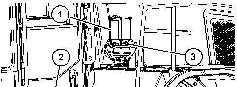
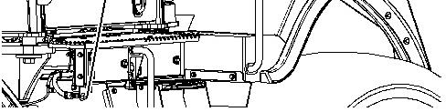
Illustration 2
g06110102
Grease reservoir (1) is located near the rear fender on the left side of the machine. Remote fill (2) is located to the left of the ladder on the left side of the machine. There is also fill location (3) on the autolube reservoir.
Note: Do not remove cover to fill.
1. Clean the fitting before filling.
2. Fill grease reservoir (1) with grease to the maximum level which is indicated on the grease reservoir (1).
Note: Do not remove lid for filling.
Reference: For the correct type of grease, refer to Operation and Maintenance Manual, Lubricant Viscosities.
Note: If a different Brand of grease is used, check for compatibility. If the new grease is not compatible with the grease in the reservoir, the system must be purged. Refer to System Operation, M0073678 for more information about purging the system. Copyright 1993 - 2024 Caterpillar Inc.
Tue Jun 25 22:22:07 UTC+0530 2024
Rights Reserved.
Product: WHEEL LOADER
Model: 980M WHEEL LOADER KRS
Configuration: 980M Wheel Loader KRS00001-UP (MACHINE) POWERED BY C13 Engine
Operation and Maintenance Manual
980M and 982M Wheel Loaders
Media Number -SEBU9054-13
-01/02/2019
Axle Oscillation Bearings - Lubricate
SMCS - 3268-086-BD; 3278-086-BD
Crushing Hazard. Connect the steering frame lock between front and rear frames before servicing the machine in the articulation area. Disconnect the steering frame lock and secure it in the stored position before resuming operation. Failure to do so could result in serious injury or death.
Ensure that the machine ignition switch is in the OFF position and that the parking brake is engaged before entering the articulation area.
Refer to Operation and Maintenance Manual, "Steering Frame Lock" before entering the articulation joint.
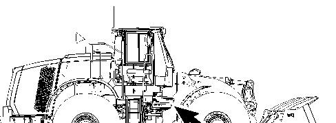
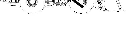
Illustration 1 g02175855
The remote grease fittings are on the right side of the machine in the articulation joint.
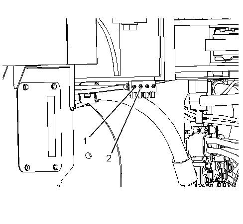
Illustration 2 g03303776
Wipe all fittings before lubricating.
Grease fitting (1) will lubricate the axle pivot bearing that is on the front of the rear axle. Grease fitting (2) will lubricate the axle pivot bearing that is on the rear of the rear axle.
Note: Refer to Operation and Maintenance Manual, "Lubricant Viscosities" for the proper grease. Copyright 1993 - 2024 Caterpillar Inc.
Product: WHEEL LOADER
Model: 980M WHEEL LOADER KRS
Configuration: 980M Wheel Loader KRS00001-UP (MACHINE) POWERED BY C13 Engine
Operation and Maintenance Manual
980M and 982M Wheel Loaders
Media Number -SEBU9054-13
Date -01/02/2019 Date Updated -28/02/2019
Backup Alarm - Test - If Equipped
SMCS - 7406-081
The backup alarm is on the rear of the machine.
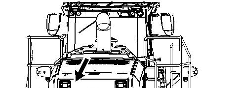
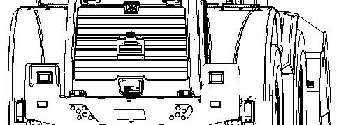

Illustration 1 g03661207
Turn the engine start switch to the ON position in order to perform the test.
Apply the service brake. Place the transmission into REVERSE.
The backup alarm should sound immediately. The backup alarm will continue to sound until the transmission is placed into NEUTRAL or into FORWARD.
Copyright 1993 - 2024 Caterpillar Inc. All Rights Reserved. Private Network For SIS Licensees. Tue Jun 25 22:31:09 UTC+0530 2024
Product: WHEEL LOADER
Model: 980M WHEEL LOADER KRS
Configuration: 980M Wheel Loader KRS00001-UP (MACHINE) POWERED BY C13 Engine
Operation and Maintenance Manual
980M and 982M Wheel Loaders
Media Number -SEBU9054-13
Battery or Battery Cable - Clean/Inspect/Replace
SMCS - 1401-040; 1401-070; 1401-510; 1402-040; 1402-070; 1402-510
-28/02/2019
Personal injury may occur from failure to properly service the batteries.
Batteries give off flammable fumes that can explode. Electrolyte is an acid and can cause personal injury if it contacts the skin or eyes.
Prevent sparks near the batteries. Sparks could cause vapors to explode. Do not allow jumper cable ends to contact each other or the engine. Improper jumper cable connections can cause an explosion.
Always wear protective glasses when working with batteries.
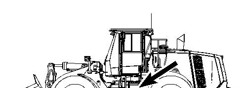
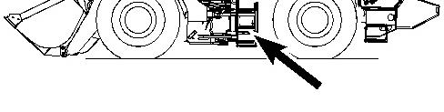
Illustration 1 g02494486
1. Turn the engine start switch key OFF. Turn all of the switches OFF.
2. Turn the battery disconnect switch OFF. Remove the key.
3. Remove the access covers from the battery compartments.
Note: The machine may contain more than one set of batteries.
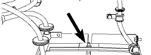
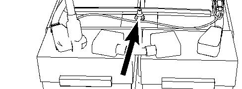

4. Remove the battery hold-down.
5. Disconnect the negative battery cable from the disconnect switch.
Note: Do not allow the disconnected battery cable to contact the disconnect switch.
6. Disconnect the negative battery cable at the battery.
7. Disconnect the positive battery cable at the battery.
8. Inspect the battery terminals for corrosion. Inspect the battery cables for wear or damage.
9. Make any necessary repairs. If necessary, replace the battery cables or the battery.
This is the sample of the manual click on the download link for complete manual
DOWNLOAD LINK
For some reason if link does not work download this pdf and then click