DOWNLOAD LINK
For some reason if link does not work download this pdf and then click
4
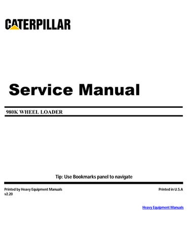
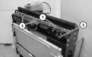
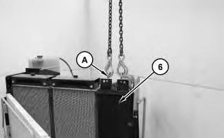
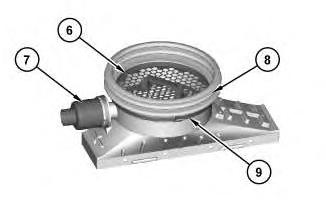
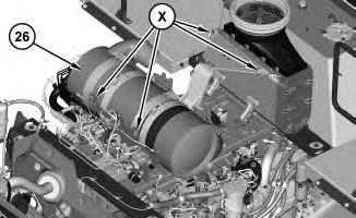
4. Attach tooling (A) and a suitable lifting device to aftercooler (6). The approximate weight of aftercooler (6) is approximately 32 kg (70 lb)
Illustration 5
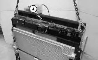
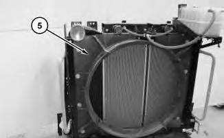
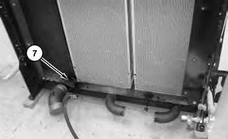
5. Remove baffle (7) .
Illustration
g02411157
g02411219
6
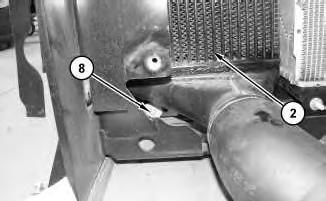
6. Remove bolts (8) and aftercooler (2) .
Installation Procedure
1. Install aftercooler (2) in the reverse order of the removal.
Copyright 1993 - 2020 Caterpillar Inc. All Rights Reserved. Private Network For SIS Licensees. Wed Dec 30 00:41:04 UTC+0530 2020
Product: WHEEL LOADER
Model: 980K WHEEL LOADER W7K
Configuration: 980K Wheel Loader W7K00001-UP (MACHINE) POWERED BY C13 Engine
Disassembly and Assembly
980K Wheel Loader C13 Engine Supplement
Media Number -KENR6443-02
i04364081
Air Cleaner - Remove and Install
SMCS - 1051-010; 1054-010
Removal Procedure
1. Open the hood.
Illustration 1 g02516636
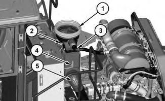
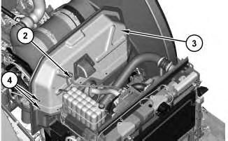
2. Disconnect the harness assemblies from temperature sensor (2) and pressure sensor (4) .
3. Disconnect hoses (3) and (5) .
4. Remove precleaner assembly (1) .
Illustration 2
g02516696
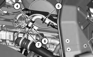
5. Remove clamp (9) and remove seal (8). Remove precleaner (6) and remove check valve (7) .
Illustration 3
g02516716
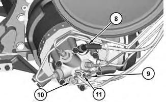
The machine andengine have beenremoved for photographic purposes.
6. Remove cover (12), primary filter element (10), and secondary filter element (11) .
Illustration 4 g02516736
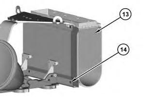
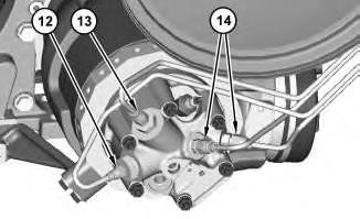
The machine andengine have beenremoved for photographic purposes.
7. Remove bolts (14) and remove air cleaner housing (13) .
Installation
Procedure
1. Install air cleaner housing (13) in the reverse order of removal.
a. Tighten bolts (14) to a torque of 15 ± 3 N·m (133 ± 27 lb in).
b. Orient check valve (7) with the marking "Top To Exhaust" facing in the upward position.
c. Tighten pressure sensor (4) to a torque of 10 ±2 N·m (89 ± 18 lb in).
d. Tighten temperature sensor (2) to a torque of 20 ± 3 N·m (177 ± 27 lb in).
Copyright 1993 - 2020 Caterpillar Inc. All Rights Reserved. Private Network For SIS Licensees.
Wed Dec 30 00:42:32 UTC+0530 2020
Product: WHEEL LOADER
Model: 980K WHEEL LOADER W7K
Configuration: 980K Wheel Loader W7K00001-UP (MACHINE) POWERED BY C13 Engine
Disassembly and Assembly
980K Wheel Loader C13 Engine Supplement
Media Number -KENR6443-02
Updated -21/08/2012
i04338971
Air Control Valve - Remove and Install - ARD Combustion, Clean Emissions Module
SMCS - 108A-010
Removal Procedure
1. Open the hood.
Illustration 1 g02477363
2. Remove clip (1) and bolts (3). Remove engine compartment shield (2) .
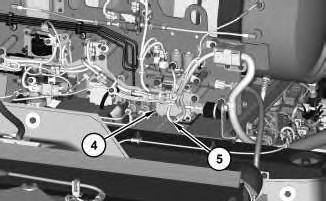
Illustration 2
Machine removed for photographic purposes.
g02494997
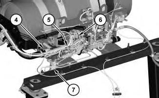
3. Disconnect harnessassemblies(5) and (6) .
4. Remove hoses (4) and (7) .
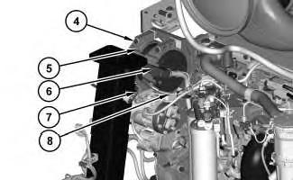
Illustration 3
g02495036
The harness assembly has beenremoved for photographic purposes.
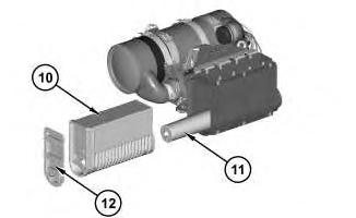
5. Remove tube assembly (12). Disconnect the hose from tube assembly (12) .
6. Remove bolts (8) and remove air control valve (10) .
7. Remove bolts (9) and remove manifold (11) .
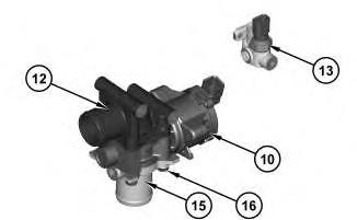
Illustration 4
8. Remove pressure sensor (13) .
9. Remove bolts (16) .
10. Remove outlet elbow (12) and inlet elbow (15) from air control valve (10) .
Installation Procedure
1. Install air control valve (10) in the reverse order of removal.
a. Tighten pressure sensor (13) to a torque of 10 ±2 N·m (89 ± 18 lb in).
Product: WHEEL LOADER
Model: 980K WHEEL LOADER W7K
Configuration: 980K Wheel Loader W7K00001-UP (MACHINE) POWERED BY C13 Engine
Disassembly and Assembly
980K Wheel Loader C13 Engine Supplement
Media Number -KENR6443-02
-21/08/2012
Air Control Valve - Remove and Install - Control Module, Clean Emissions Module
SMCS - 108A-010
Removal Procedure
1. Open the hood.
Illustration 1 g02477363
2. Remove clip (1) and bolts (3). Remove engine compartment shield (2) .
i04338970
2
3. Disconnect harnessassembly (5). Remove control module (4) .
Installation Procedure
1. Install control module (4) in the reverse order of removal.
Copyright 1993 - 2020 Caterpillar Inc. All Rights Reserved. Private Network For SIS Licensees. Wed Dec 30 00:37:57 UTC+0530 2020
Product: WHEEL LOADER
Model: 980K WHEEL LOADER W7K
Configuration: 980K Wheel Loader W7K00001-UP (MACHINE) POWERED BY C13 Engine
Disassembly and Assembly
980K Wheel Loader C13 Engine Supplement
Media Number -KENR6443-02
Updated -21/08/2012
i04321506
Alternator - Remove and Install
SMCS - 1405-010
Removal Procedure
Personal injury canresult from failure to disconnect the battery.
First, disconnect the negative battery cable. Then, disconnect the positive battery cable.
Apositive power lead can cause sparks if the battery is not disconnected. Sparks can possibly result in battery explosion or fire.
1. Open the hood.
2. Disconnect the battery cables.
3. Refer to Operation and Maintenance Manual, "Belt - Inspect/Adjust/Replace" for removing and installing the serpentine belt.
Illustration 1
4. Remove clip (1) and bolts (3). Remove engine compartment shield (2) .
Illustration 2
g02477369
Machine andthe support assemblyhavebeen removedfor photographic purposes.
5. Disconnect ground strap (7). Disconnect harness assemblies (6) and (8) .
6. Remove bolts (4) and remove alternator (5) .
g02477363
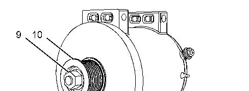
Illustration 3 g02477374
7. Remove nut (9) and remove pulley (10) .
Installation Procedure
1. Install alternator (5) in reverse order of removal.
a. Tighten nut (9) to a torque of 127 ± 10 N·m (94 ± 8 lb ft).
b. Tighten the nut for harness assembly (6) to a torque of 18 ± 2 N·m (161 ± 21 lb in).
c. Tighten the bolt for harness assembly (8) and ground strap (7) to a torque of 4.4±1 N·m (39 ± 9 lb in).
Copyright 1993 - 2020 Caterpillar Inc. All Rights Reserved. Private Network For SIS Licensees. Wed Dec 30 00:26:53 UTC+0530 2020
Product: WHEEL LOADER
Model: 980K WHEEL LOADER W7K
Configuration: 980K Wheel Loader W7K00001-UP (MACHINE) POWERED BY C13 Engine
Disassembly and Assembly
980K Wheel Loader C13 Engine Supplement
Batteries - Remove and Install
SMCS - 1401-010; 1408-010
Removal Procedure
Accidental machine starting can cause injury or death to personnel working on the machine.
To avoid accidental machine starting, turn the battery disconnect switch to the OFF position and remove the key. If the machine is not equipped with a battery disconnect switch, disconnect the battery cables from the battery and tape the battery clamps.
Place a do not operate tag at the battery disconnect switch location to inform personnel that the machine is being worked on.
1. Turn the battery disconnect switch to the OFF position.
i04316311
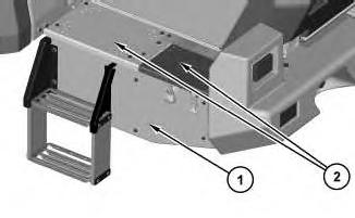
1
2. Remove panels (2) and remove panel (1) .
Note: The steps can be removed prior to the removal of panel (1), or with panel (1) .
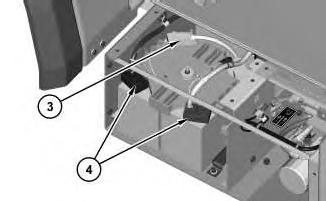
Illustration 2
3. Remove harness assembly (3) .
4. Disconnect harness assemblies (4) and position out of the way.
Illustration
g02476162
g02476165
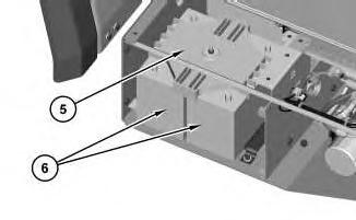
3
5. Remove battery hold-down (5). Remove batteries (6). The batteries weigh approximately 27 kg (60 lb), each.
Installation Procedure
1. Install batteries (6) in the reverse order of removal.
a. Tighten the nuts for harness assemblies (3) and (4) to a torque of 7.2 ± 1.6 N·m (64 ± 14 lb in). Copyright 1993 - 2020 Caterpillar Inc. All Rights Reserved. Private Network For SIS Licensees.
Product: WHEEL LOADER
Model: 980K WHEEL LOADER W7K
Configuration: 980K Wheel Loader W7K00001-UP (MACHINE) POWERED BY C13 Engine
Disassembly and Assembly
980K Wheel Loader C13 Engine Supplement
Media Number -KENR6443-02
i04319856
Belt Tensioner - Remove and Install
SMCS - 1358-010
Removal Procedure
Table 1
Required Tools
1. Open the engine hood.
Illustration 1
2. Remove cover assembly (1) .
Illustration 2
g02477297
3. Remove clip (2) and bolts (4). Remove engine compartment shield (3) .
Illustration 3
g02477300
Machine has beenremoved for photographic purposes.
Note: Note the location of serpentine belt (5) in Illustration 3 for installation.
4. Insert Tooling (A) into Location (Y). Use Tooling (A) to release the tension on serpentine belt (5). Pin belt tensioner (7) at Location (X).
5. Remove serpentine belt (5). Remove bolt (6) and remove belt tensioner (7) .
Installation Procedure
1. Install belt tensioner (7) in the reverse order of removal.
a. Tighten bolt (6) to a torque of 41 ±8 N·m (30 ± 6 lb ft).
Copyright 1993 - 2020 Caterpillar Inc. All Rights Reserved. Private Network For SIS Licensees. Wed Dec 30 00:26:37 UTC+0530 2020
Product: WHEEL LOADER
Model: 980K WHEEL LOADER W7K
Configuration: 980K Wheel Loader W7K00001-UP (MACHINE) POWERED BY C13 Engine
Disassembly and Assembly
980K Wheel Loader C13 Engine Supplement Media Number -KENR6443-02
Clean Emissions Module - Remove and Install
SMCS - 1050-010; 1050; 7279-010; 7279
Removal Procedure
Table 1
Required Tools
Start By:
A. Remove exhaust elbow.
B. Remove exhaust pipe.
Hot engine components can cause injury from burns. Before performing maintenance on the engine, allow the engine and the components to cool.
i04333909
Wear goggles, gloves, protective clothing, and a National Institute for Occupational Safety and Health(NIOSH) approved P95 or N95 halfface respirator when handling a used Diesel Particulate Filter or Catalytic Converter Muffler. Failure to do so could result in personal injury.
1. Turn the fuel supply to the OFF position and turn the power disconnect switch to the OFF position.
2. Drain the coolant to a level that is below the combustion head group.
Illustration 1
g02477363
3. Remove clip (1) and bolts (3). Remove engine compartment shield (2) .
Illustration 2 g02489496
4. Loosen clamp assembly (5) .
Note: Place locating markson each tube assembly and the clamp assemblies prior to removal.
5. Remove clips (4). Remove bolts(6) and position tube assembly (7) out of the way.
Illustration 3
g02489522
6. Remove bolt (9) and the ground strap. Disconnect cable assembly (8) .
7. Remove allen bolt (11), remove the hold down clamp, and disconnect the cable assembly.
8. Use Tooling (A) to disconnect flame detection sensor (10) .
Illustration 4 g02489536
Note: Cap all tube assembliesand fittings that are disconnected to prevent fluid loss. This action will also keep contaminantsout of the system.
9. Disconnect tube assemblies (12) and (13) .
10. Disconnect tube assemblies (14) .
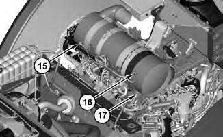
Illustration 5
g02489558
11. Disconnect pressure sensors (15), temperature sensor (16), and soot antennas (17) .
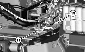
Illustration 6
12. Disconnect tube assemblies (18) .
g02489616
13. Loosen clamp (19) and position the hose out of the way.
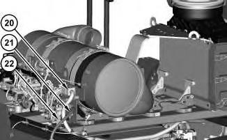
14. Disconnect harnessassembly (20) .
15. Disconnect hose assembly (21) and remove bracket (22) .
Illustration 7
g02489699
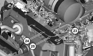
Illustration 8
g02501523
This is the sample of the manual click on the download link for complete manual