Installation Procedure
Table 2 Required Tools Tool
A 138-7573 Link Bracket 2
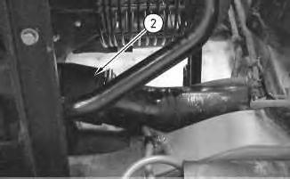
1. Use the hoist and Tooling (A) to install the aftercooler core. The weight of the aftercooler core is 34 kg (75 lb).
6
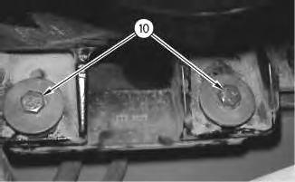
2. Install two bolts (10) which hold the base of the aftercooler core in place.
7
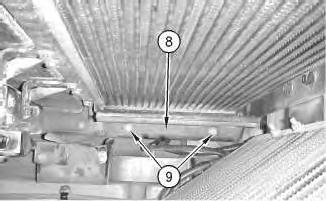
3. Install guard (8) and install four bolts (9) .
Illustration
g00798334
Illustration
g00800870
8
4. Remove Tooling (A) .
5. Install bracket (3) and install four bolts (5) which hold the bracket in place.
6. Install bracket (6) and install two bolts (4) which hold the bracket in place. Install two bolts (7) which hold the aftercooler core in place.
7. Swing the refrigerant condenser into the closed position on the ATAAC core. Secure the latch of the refrigerant condenser.
9
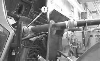
8. Install tube assembly (2). Tighten the clamps which hold tube assembly (2) in place.
Illustration
g00798318
Illustration
g00798313
10
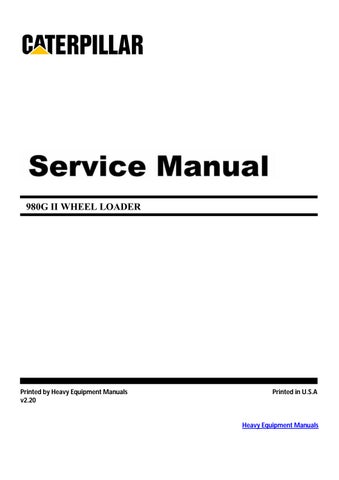
9. Install tube assembly (1). Tighten the clamps which hold tube assembly (1) in place.
10. Close the engine hood.
End By: Separate the steering frame lock. Refer to Disassembly and Assembly, "Steering Frame Lock - Separate and Connect".
1993 - 2020 Caterpillar Inc.
Product: WHEEL LOADER
Model: 980G II WHEEL LOADER AYT
Configuration: 980G SERIES II WHEEL LOADER AYT00001-UP (MACHINE) POWERED BY 3406E
Disassembly and Assembly
980G Series II Wheel Loader Engine Supplement
i01534673
Air Cleaner - Remove and Install
SMCS - 1051-010; 1054-010
Removal Procedure
Start By:
A. Connect the steering frame lock. Refer to Disassembly and Assembly, "Steering Frame LockSeparate and Connect".
1. Open the engine hood. The air cleaner is located on the left side of the machine.
Illustration 1
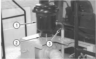
2. Loosen clamp (2) and hose clamp (3). Remove precleaner (1) .
Illustration 2
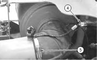
3. Disconnect electrical connector (4) .
g00796972
4. Loosen clamp (5) and move the tube assembly away from the air cleaner assembly.
Illustration 3
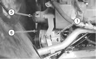
5. Disconnect electrical connector (6) .
g00514336
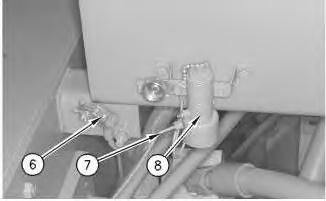
6. Disconnect line (7) from the starting aid valve assembly (8) .
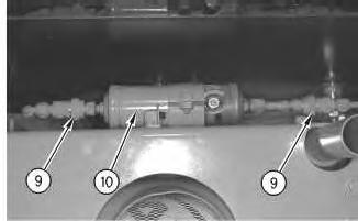
Illustration 4
g00514411
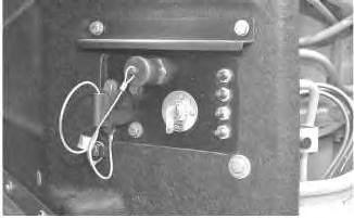
7. Disconnect air conditioning dryer (10) at the quick-connect fittings (9) .
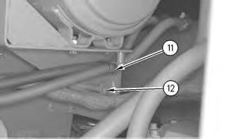
Illustration 5
g00514321
8. Remove bolts (11) and (12). Move the heater hoses and the wire harness away from the air cleaner assembly.
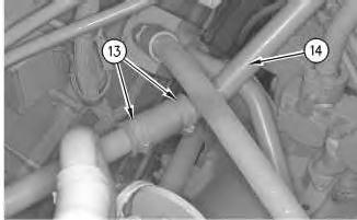
6
9. Loosen hose clamps (13). Remove the hose from dust ejector tube (14) .
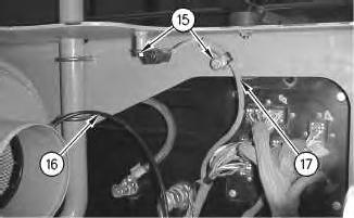
7
10. Remove two bolts (15) which hold wire harness (17) in place. Remove wire harness (17) .
11. Remove line (16) .
Illustration
g00514322
Illustration
g00797002
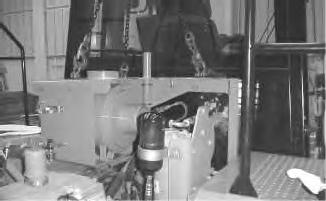
Illustration 8
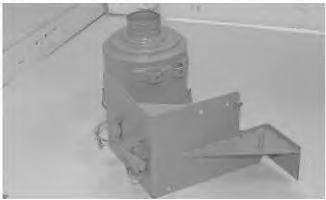
12. Use a hoist and a suitable lifting device to support the air cleaner assembly, as shown.
Illustration 9
g00797022
Illustration 10
g00797023
g00796997
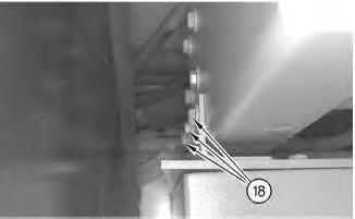
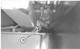
13. Remove bolts (18) from both sides of the air cleaner support.
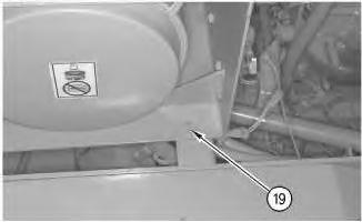
Illustration 11
14. Remove bolt (19) .
15. Remove the air cleaner assembly. The weight of the air cleaner assembly is 93 kg (205 lb).
Note: Use the following procedure to remove the air cleaner housing.
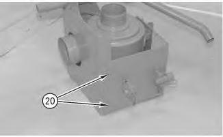
Illustration 12
16. Remove bolts (20) .
g00797024
g00797027
13
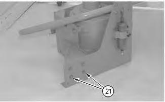
17. Remove bolts (21). Separate the two halves.
Illustration 14
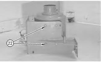
18. Remove bolts (22) .
Illustration
g00797028
g00797029
Illustration 15
19. Remove the air cleaner housing.
Installation Procedure
g00514332
Illustration 16
g00514332
Illustration 17
g00797029
1. Install the air cleaner housing and install bolts (22) .
Illustration 18
2. Assemble the air cleaner mounting and install bolts (21) .
Illustration 19
3. Install bolts (20) on the adjacent side of the mounting frame.
g00797028
g00797027
Illustration 20 g00796997
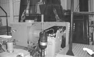
4. Use a hoist and a suitable lifting sling to support the air cleaner assembly, as shown. The weight of the air cleaner assembly is 93 kg (205 lb).
Illustration 21
g00797024
5. Install air cleaner assembly on the machine and install bolt (19) .
Illustration 22
g00797023
6. Install bolts (18) on both sides of the air cleaner support.
7. Remove the hoist and the lifting device.
8. Install line (16) .
9. Install wire harness (17). Install two bolts (15) which hold wire harness (17) in place.
Illustration 23
g00797022
Illustration 24
g00797002
25
10. Install the hose on dust ejector tube (14) and tighten hose clamps (13) .
26
11. Install bolt (12) that secures the wire harness.
12. Install bolt (11) that secures the heater hoses.
Illustration
g00514322
Illustration
g00514321
Illustration 27
g00514411
13. Connect air conditioning dryer (10) to quick-connect fittings (9) .
Illustration 28
14. Connect electrical connector (6) .
g00514336
15. Connect line (7) to starting aid valve assembly (8) .
Illustration 29
g00796972
16. Install the tube assembly to the air cleaner assembly, and tighten hose clamp (5) .
17. Connect electrical connector (4) .
Illustration 30
g00514333
18. Install precleaner (1). Tighten clamp (2) and hose clamp (3) at the dust ejector.
19. Close the engine hood.
End By: Separate the steering frame lock. Refer to Disassembly and Assembly, "Steering Frame Lock - Separate and Connect".
Copyright 1993 - 2020 Caterpillar Inc. All Rights Reserved. Private Network For SIS Licensees. Thu Jun 4 17:11:10 UTC+0530
Product: WHEEL LOADER
Model: 980G II WHEEL LOADER AYT
Configuration: 980G SERIES II WHEEL LOADER AYT00001-UP (MACHINE) POWERED BY 3406E
Disassembly and Assembly
980G Series II Wheel Loader Engine Supplement
Alternator - Remove and Install - Engine in Chassis
SMCS - 1405-010
Removal Procedure
Start By:
i01525704
A. Connect the steering frame lock. Refer to Disassembly and Assembly, "Steering Frame LockSeparate and Connect".
1. Open the engine hood. The alternator is located on the right side of the machine.
2. Open the engine side panel on the right side of the machine.
Illustration 1
Accidental machine starting can cause injury or death to personnel working on the machine.
To avoid accidental machine starting, turn the battery disconnect switch to the OFF position and remove the key. If the machine is not equipped with a battery disconnect switch, disconnect the battery cables from the battery and tape the battery clamps.
Place a do not operate tag at the battery disconnect switch location to inform personnel that the machine is being worked on.
3. Turn the battery disconnect switch to the OFF position.
Illustration 2
g00792538
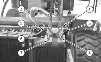
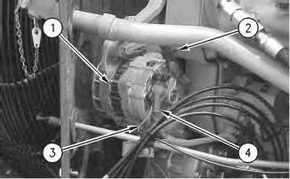
Note: Put identification marks on all wires for installation purposes.
4. Disconnect ground wire (2) and positive wire (4) .
5. Disconnect wire (3) .
3
6. Use belt tensioner (5) in order to release the tension on serpentine belt (6). Refer to Operation and Maintenance Manual, SEBU7362, "980G Series II Wheel Loader", "BeltsInspect/Adjust/Replace".
7. Remove serpentine belt (6) from the pulley of alternator (1) .
4
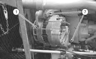
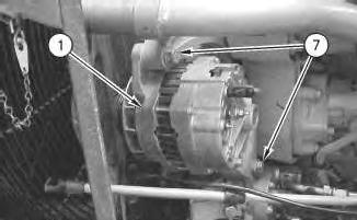
8. Remove two pivot bolts (7) from alternator (1). Remove the alternator.
Installation Procedure
Illustration
g00792556
Illustration
g00792779
Illustration 5
1. Install alternator (1) on the alternator mounting bracket. Install two pivot bolts (7) .
Illustration 6
g00792556
2. Install serpentine belt (6) on the pulley of alternator (1) .
3. Use belt tensioner (5) in order to apply tension to serpentine belt (6). Refer to Operation and Maintenance Manual, SEBU7362, "980G Series II Wheel Loader", "BeltsInspect/Adjust/Replace".
g00792779
Illustration 7
4. Connect wire (3) to alternator (1) .
g00792538
5. Connect ground wire (2) and positive wire (4) .
Illustration 8
g00532583
6. Turn the battery disconnect switch to the ON position.
7. Close the engine side panel.
8. Close the engine hood.
End By: Separate the steering frame lock. Refer to Disassembly and Assembly, "Steering Frame Lock - Separate and Connect".
Product: WHEEL LOADER
Model: 980G II WHEEL LOADER AYT
Configuration: 980G SERIES II WHEEL LOADER AYT00001-UP (MACHINE) POWERED BY 3406E
Disassembly and Assembly
980G Series II Wheel Loader Engine Supplement Media
i01532546
Belt Tensioner - Remove and Install
SMCS - 1358-010
Removal Procedure
Table 1 Required Tools
Start By:
A. Connect the steering frame lock. Refer to Disassembly and Assembly, "Steering Frame LockSeparate and Connect".
1. Open the engine hood.
This is the sample of the manual click on the download link for complete manual