Product: WHEEL LOADER
Model: 980C WHEEL LOADER 2XD
Configuration: 980C WHEEL LOADER 2XD00001-UP (MACHINE) POWERED BY 3406 ENGINE
Disassembly and Assembly
26SI Series Alternator
Media Number -RENR1252-01
Alternator - Assemble
SMCS - 1405-016
Assembly
Procedure
i01167078
Note: Cleanliness is an important factor. Before assembly, all parts should be thoroughly cleaned in cleaning fluid. Allow the parts to air dry. Wiping cloths or rags should not be used to dry parts. Lint may be deposited on the parts which may cause later trouble. Inspect all parts. If any parts are worn or damaged, use new parts for replacement.
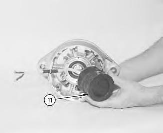
Note: Do not strike the diodes. The shock of such an impact can damage the diodes. Use proper tools in order to press the diodes in the mountings.
Illustration 1
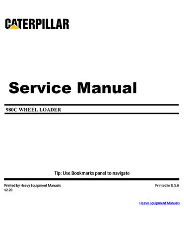
1. Install 3 diodes (11) in heat sink (12) .
g00628072
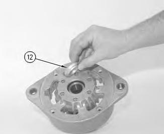
Illustration 2
g00628068
Note: Do not strike the bushing. Shocks from striking the housing can cause damage.
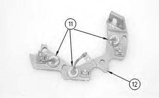
2. Press bushing (43) in housing (14) .
3. Install 3 diodes (13) in housing (14) .
Illustration 3
g00628067
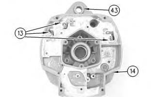
4. Press collar (42) on rotor (39) .
5. Slide retainer (41) on rotor (39) .
6. Press bearing (40) on rotor (39) .
Illustration 4
g00628063
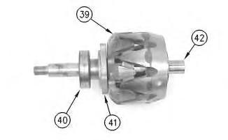
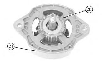
7. Press housing (31) on rotor (39) and bearing (40) .
8. Install 4 screws (38) in housing (31) .
Illustration 5
g00628057
Note: Do not strike the bearing. Shocks from striking the housing can cause damage.
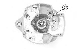
9. Install the inner race. Press bearing (37) into the housing.
This is the sample of the manual click on the download link for complete manual
DOWNLOAD LINK
For some reason if link does not work download this pdf and then click
Illustration 6
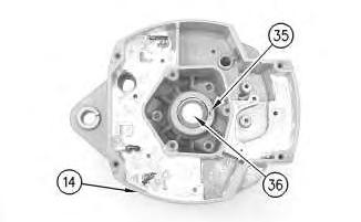
10. Press cap (36) in housing (14) .
g00628043
Illustration 7
g00628041
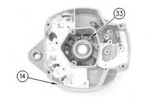
11. Install the coil and support (34) in housing (14). Guide the field leads and the grommet through the hole as the coil is installed in housing (14). Install 3 screws (33) .
Illustration 8
g00628037
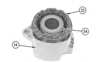
12. Press the stator (32) and housing (14) together. Guide the stator leads and the grommet through the hole as the stator is installed in housing (14) .
Illustration 9
g00628035
Note: Do not damage exposed stator windings or field windings. Bumping the windings or scraping the windings may break the insulation. Broken insulation may create a short circuit or a ground.
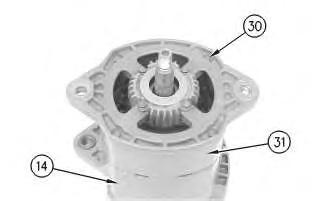
13. Join housing (31) and housing (14). Install 4 bolts (30) .
Illustration 10
g00627853
Note: Many of the alternator's internal components are covered with dielectric grease. If the grease is removed, reapply the grease.
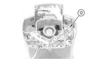
11
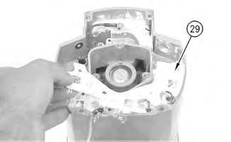
14. Install Insulator (29). Install the heat sink and diode assembly (12) in housing (14) .
12
15. Install separator (28) .
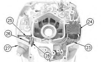
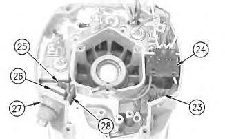
16. Install alternator output terminal (27). Install insulator (26). Install the nut and washer (25) .
17. Install diode trio (24) and install screw (23) .
Illustration
g00627855
Illustration
g00627840
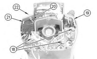
Illustration 13
g00627832
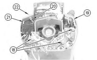
18. Install the 3 screws and insulators (18). Connect wire (19) .
19. If the "R" terminal is used, install the following components: nut (20), lead (21), the washer and terminal (21) .
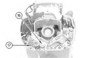
Illustration 14
g00627820
20. Install the screw and insulator (16). Connect capacitor lead (17) .
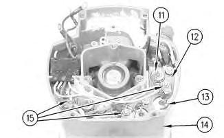
Illustration 15
g00627810
Note: The 3 output diodes (11) are located in heat sink (12). These diodes are identical in polarity. Diode (11) has red insulation on the wire. The 3 ground diodes (13) are located in housing (14). These diodes are identical in polarity. Diode (13) has black insulation on the wire.
21. Connect 6 diode leads. Connect 3 phase leads. Connect 3 stator phase leads. Install 3 nuts (15).
Table 1
Alternator Ground
Negative
Current Flow of the Output Diodes
Lead to the Heat Sink
Current Flow of the Ground Diodes
Housing to the Lead Red Wire Black Wire
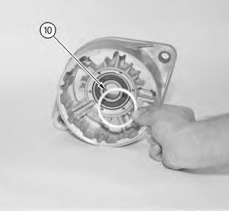
Illustration 16
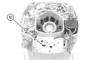
22. Install mounting plate (10).
g00627808
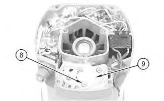
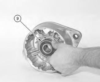
Illustration 17
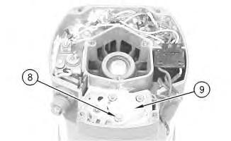
23. Install regulator (9) .
24. Install grounded mounting screw (8) .
g00627804
18
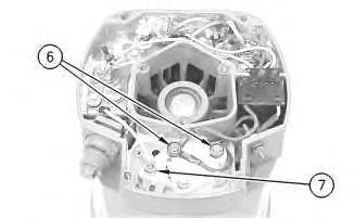
25. Install 2 insulated screws (6). Connect the 3 leads.
Note: The regulator and the mounting plate are coated with dielectric grease. If the grease is removed, reapply the grease.
26. Install nut (7) and connect the wire.
19
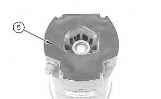
27. Install gasket (5) .
Illustration
g00627796
Illustration
g00627794
20
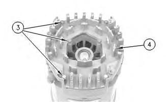
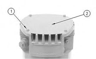
28. Position cover (4). Install 7 screws (3) .
21
29. Position plate (2). Install 4 screws (1) .
30. Install the fan, the pulley, the washer, and the pulley nut.
1993 - 2021 Caterpillar Inc.
15:32:58 UTC+0530 2021
Illustration
g00627792
Illustration
g00627790
Product: WHEEL LOADER
Model: 980C WHEEL LOADER 2XD
Configuration: 980C WHEEL LOADER 2XD00001-UP (MACHINE) POWERED BY 3406 ENGINE
Disassembly and Assembly
26SI Series Alternator
Alternator - Disassemble
SMCS - 1405-015
Disassembly Procedure Table 1 Required Tools
i01167081
Start By:
A. Remove the alternator. Refer to Disassembly and Assembly, "Alternator - Remove" for the machine that is being serviced.
Note: Cleanliness is an important factor. Before the disassembly procedure, the exterior of the component should be thoroughly cleaned. This will help to prevent dirt from entering the internal mechanism.
1. Remove the pulley nut, the washer, the pulley, and the fan.
Illustration 1
2. Remove 4 screws (1). Remove plate (2) .
Illustration 2
3. Remove 7 screws (3). Remove cover (4) .
Illustration 3
4. Remove gasket (5) .
g00627790
g00627792
g00627794
Illustration 4
5. Remove 2 insulated screws (6). Remove the 3 leads.
Note: The regulator and the mounting plate are coated with dielectric grease. If the grease is removed, reapply the grease.
6. Remove nut (7) .
Illustration 5
7. Remove grounded mounting screw (8) .
8. Remove regulator (9) .
g00627796
g00627804
Illustration 6
g00627808
9. Remove mounting plate (10). The mounting plate may be stuck to the regulator.
Illustration 7
g00627810
Note: The 3 output diodes (11) are located in heat sink (12). These diodes are identical in polarity. Diode (11) has red insulation on the wire. The 3 ground diodes (13) are located in housing (14). These diodes are identical in polarity. Diode (13) has black insulation on the wire.
10. Remove 3 nuts (15). Disconnect 3 stator phase leads. Disconnect 3 phase leads. Disconnect 6 diode leads.
Table 2
Alternator Ground Current Flow of the Output Diodes Current Flow of the Ground Diodes
Negative
Lead to the Heat Sink Housing to the Lead Red Wire Black Wire
Illustration 8
g00627820
11. Remove the screw and insulator (16). Disconnect capacitor lead (17) .
Illustration 9
g00627832
12. Remove the 3 screws and insulators (18). Disconnect wire (19) .
13. If the "R" terminal is used, remove the following components: nut (20), lead (21), the washer and terminal (21) .
Illustration 10
14. Remove screw (23) and remove diode trio (24) .
15. Remove the nut and washer (25). Remove insulator (26). Remove alternator output terminal (27) .
16. Remove separator (28) .
Illustration 11
g00627853
Note: Many of the alternator's internal components are covered with dielectric grease. If the grease is removed, reapply the grease.
Illustration 12
g00627855
17. Remove the heat sink and diode assembly (12) from housing (14). Insulator (29) may be stuck to heat sink (12) .
Illustration 13
g00628035
Note: Do not damage exposed stator windings or field windings. Bumping the windings or scraping the windings may break the insulation. Broken insulation may create a short circuit or a ground.
18. Remove 4 bolts (30). Carefully separate housing (31) from housing (14) .
Illustration 14
g00628037
19. Pull apart stator (32) and housing (14). Guide the stator leads and the grommet through the hole as the stator is removed from housing (14) .
Illustration 15
g00628041
20. Remove 3 screws (33). Remove the coil and support (34) from housing (14). Guide the field leads and the grommet through the hole as the coil is removed from housing (14) .
Illustration 16
g00628043
21. Position a small screwdriver in slot (35). Pry cap (36) from housing (14) .
Illustration 17
g00628057
Note: Do not strike the bearing. Shocks from striking the housing can cause damage.
22. Wipe the excess grease from the bearing well. Press bearing (37) into the housing. Remove the inner race.
Illustration 18
23. Remove 4 screws (38) from housing (31) .
g00628063
24. Lift rotor (39) and bearing (40) from housing (31) .
Illustration 19
25. Pull bearing (40) from rotor (39) .
26. Pull retainer (41) from rotor (39) .
27. Pull collar (42) from rotor (39) .
g00628067
Illustration 20
g00628068
Note: Do not strike the bushing. Shocks from striking the housing can cause damage.
28. Press bushing (43) from housing (14) .
Note: Do not strike the diodes. The shock of such an impact can damage the diodes. Use proper tools in order to press or pull the diodes from the mountings. As much as 890 N (200 lb) of force may be needed to remove a diode.
29. Remove 3 diodes (13) from housing (14) .
Illustration 21
30. Remove diode (11) from heat sink (12) .
g00628072
Copyright 1993 - 2021 Caterpillar Inc. All Rights Reserved. Private Network For SIS Licensees.
Mon Jul 5 15:32:47 UTC+0530 2021
Product: WHEEL LOADER
Model: 980C WHEEL LOADER 2XD
Configuration: 980C WHEEL LOADER 2XD00001-UP
Disassembly and Assembly N3 Series Brushless Alternators
Alternator - Assemble
SMCS - 1405-016
Assembly Procedure Table 1
Soldering
Vise or clamping support with vee blocks Press
i01688996
Illustration 1
g00871248
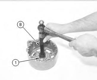
1. Install the roller bearing (1) with tooling (B) .
Note: If necessary, apply grease to the bearing.
Illustration 2
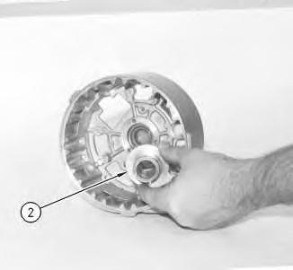
2. Install the ring (2) in the rear frame.
g00871460
Illustration 3 g00871252
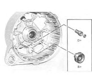
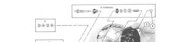
3. Install the insulators for terminal "B+" and terminal "D+".
Illustration 4
4. Install the "R" terminal, if the "R" terminal was replaced.
5. Install the rectifier (3) in the rear frame.
6. Install the two screws. Solder the sleeve (4) over terminal "R".
7. Install the following components on terminals: "D+", "B+" and B-: terminal insulators, washers and nuts.
g00871347
Illustration 5
g00871376
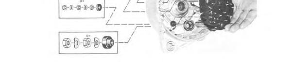
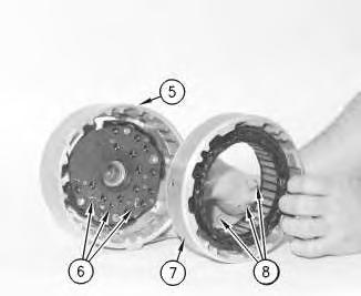
8. Position the stator frame (7) on the rear frame (5). Use the marks on the alternator that were made in the disassembly procedure for alignment.
Illustration 6
g00871382
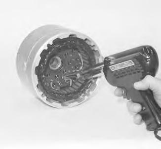
9. Solder the leads for the stator winding (8) to the terminals for the rectifier (6) .
Illustration 7
10. Install the bearing (9) in the rear frame.
Note: The bearing is a loose fit.
g00871385
Illustration 8
11. Install the intermediate ring (10) .
g00871389
9
12. Install the field winding (11). The leads for the winding must fit in the deep groove. Install the six screws on the reverse side of the frame.
13. Apply the epoxy putty 5P-3321 Adhesive over the lead and the groove.
Illustration 10
14. Install the spacer ring (12) .
g00871407
Illustration
g00871402
This is the sample of the manual click on the download link for complete manual