
Note: Use Bookmarks panel to navigate
This is the sample of the manual click on the download link for complete manual
Note: Use Bookmarks panel to navigate
This is the sample of the manual click on the download link for complete manual
For some reason if link does not work download this pdf and then click

Product: WHEEL LOADER
Model: 972K WHEEL LOADER Z4W
Configuration: 972K Wheel Loader Z4W00001-UP (MACHINE) POWERED BY C9.3 Engine
Disassembly and Assembly
966K and 972K Wheel Loaders Machine Systems
Media Number -KENR5833-02
Publication Date -01/03/2011 Date Updated -09/08/2019
SMCS - 4331-010; 5077-010
Removal Procedure
Start By:
a. Release hydraulic system pressure.
b. Hydraulic tank oil - retain.
Hot oil and components can cause personal injury.
Do not allow hot oil or components to contact skin.
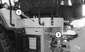
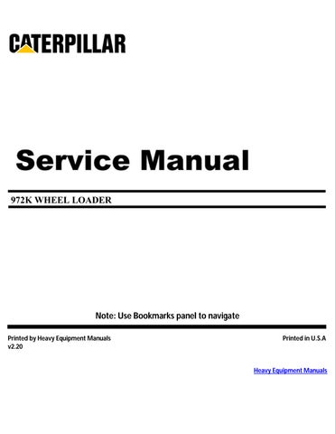
Illustration 1
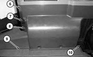
1. Remove platform (1). Open door (2).
Illustration 2 g02290434
2. Disconnect fitting (5). Remove clamps (4) and accumulator (3).
1. Install accumulator (3) in the reverse order of the removal.
Copyright 1993 - 2023 Caterpillar Inc. All Rights Reserved. Private Network For SIS Licensees. Mon Feb 27 22:24:29 UTC+0530 2023
Product: WHEEL LOADER
Model: 972K WHEEL LOADER Z4W
Configuration: 972K Wheel Loader Z4W00001-UP (MACHINE) POWERED BY C9.3 Engine
Disassembly and Assembly
966K and 972K Wheel Loaders Machine Systems
Media Number -KENR5833-02
Publication Date -01/03/2011
Date Updated -09/08/2019
SMCS - 107P-HFN
Removal Procedure
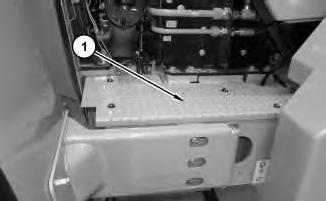
Illustration 1
1. Remove cover (1).
2. Disconnect harness assemblies (2), hose assembly (3), hose (4), bolts (5). Remove air pump (6).
1. Install air pump (6) in the reverse order of the removal.
Copyright 1993 - 2023 Caterpillar Inc. All Rights Reserved. Private Network For SIS Licensees. Mon Feb 27 22:28:06 UTC+0530 2023
Product: WHEEL LOADER
Model: 972K WHEEL LOADER Z4W
Configuration: 972K Wheel Loader Z4W00001-UP (MACHINE) POWERED BY C9.3 Engine
Disassembly and Assembly
966K and 972K Wheel Loaders Machine Systems
Media Number -KENR5833-02 Publication Date -01/03/2011 Date Updated -09/08/2019
SMCS - 7304-010-FM; 7309-010-FM; 7309-011-FM; 7311-010-FM; 7320-010-FM
Removal Procedure
Start By:
a. Remove the seat.
1
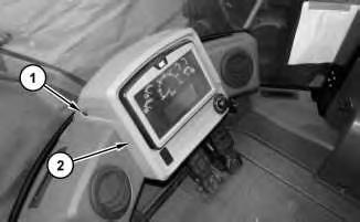
1. Remove four screws (1) and lower display assembly (2) out of the way.
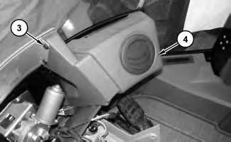
2. Remove eight screws (3) and air duct (4).
3
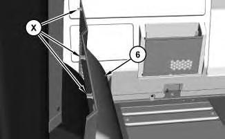
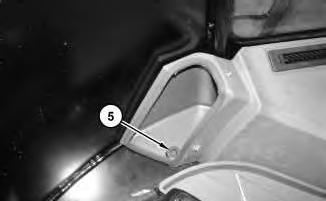
4. Remove holder (10). Remove four screws (8). Fold floor mat (9) out of the way. Carefully remove panel (6). There are three locking tabs (X) at the top on the opposite side of panel (6). Disconnect the harness assembly for auxiliary power port (7).
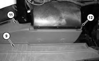
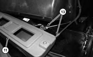
5. Remove two screws (12). Fold floor mat (9) back and slide duct (11) out in order to disconnect harness assemblies (13). Remove air duct (11).
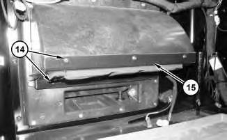
8
6. Remove six screws (14) and lower blower motor support bracket (15).
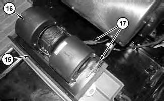
9
7. Disconnect harness assemblies (17). Separate blower motor (16) from blower motor support bracket (15).
1. Install blower motor (16) in the reverse order of the removal.
Copyright 1993 - 2023 Caterpillar Inc. All Rights Reserved. Private Network For SIS Licensees. Mon Feb 27 22:52:45 UTC+0530 2023
Product: WHEEL LOADER
Model: 972K WHEEL LOADER Z4W
Configuration: 972K Wheel Loader Z4W00001-UP (MACHINE) POWERED BY C9.3 Engine
Disassembly and Assembly
966K and 972K Wheel Loaders Machine Systems
Media Number -KENR5833-02 Publication Date -01/03/2011 Date Updated -09/08/2019
SMCS - 4263-010
Removal Procedure
Start By:
A. System pressure release.
B. Hydraulic oil - retain.
Hot oil and components can cause personal injury.
Do not allow hot oil or components to contact skin.
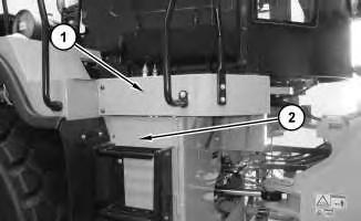
Illustration 1 g02286333
1. Remove platform (1) . Open door (2) .
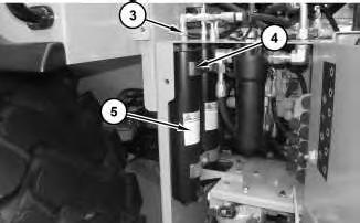
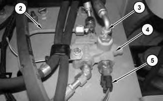
Illustration 2
g02286374
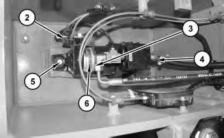
Note: As an option, one of the brake accumulators may be located on the outside of the step compartment.
2. Disconnect all hose assemblies (3) . Remove clamps (4) and brake accumulators (5) .
1. Install brake accumulators (5) in the reverse order of the removal.
Copyright 1993 - 2023 Caterpillar Inc. All Rights Reserved. Private Network For SIS Licensees. Mon Feb 27 22:32:39 UTC+0530 2023
Product: WHEEL LOADER
Model: 972K WHEEL LOADER Z4W
Configuration: 972K Wheel Loader Z4W00001-UP (MACHINE) POWERED BY C9.3 Engine
Disassembly and Assembly
966K and 972K Wheel Loaders Machine Systems
Media Number -KENR5833-02
Publication Date -01/03/2011 Date Updated -09/08/2019
SMCS - 4282-016
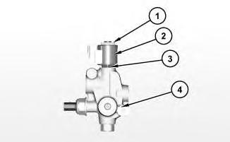
Illustration 1
g02286096
1. Install cartridge assembly (3). Tighten cartridge assembly (3) to the following torque 27 ± 1.35 N·m (20± 1lb ft). Install coil assembly (2). Install nut (1). Tighten nut (1) to the following torque 6.1 ± 0.7 N·m (54 ± 6 lb in)
End By:
a. Install the parking brake control valve.
Copyright 1993 - 2023 Caterpillar Inc.
All Rights Reserved.
Private Network For SIS Licensees. Mon Feb 27 22:34:36 UTC+0530 2023
Product: WHEEL LOADER
Model: 972K WHEEL LOADER Z4W
Configuration: 972K Wheel Loader Z4W00001-UP (MACHINE) POWERED BY C9.3 Engine
Disassembly and Assembly
966K and 972K Wheel Loaders Machine Systems
Media Number -KENR5833-02
Publication Date -01/03/2011 Date Updated -09/08/2019
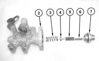
SMCS - 4282-015
Disassembly Procedure
Start By:
a. Remove the parking brake control valve.
Illustration 1
i04074529
g02286096
1. Remove nut (1), coil assembly (2), and cartridge assembly (3) from control valve (4).
Copyright 1993 - 2023 Caterpillar Inc. All Rights Reserved. Private Network For SIS Licensees.
Mon Feb 27 22:34:19 UTC+0530 2023
Product: WHEEL LOADER
Model: 972K WHEEL LOADER Z4W
Configuration: 972K Wheel Loader Z4W00001-UP (MACHINE) POWERED BY C9.3 Engine
Disassembly and Assembly
966K and 972K Wheel Loaders Machine Systems
Media Number -KENR5833-02
Publication Date -01/03/2011 Date Updated -09/08/2019
SMCS - 4282-010
Removal Procedure
Hot oil and components can cause personal injury.
Do not allow hot oil or components to contact skin.
1. Release the hydraulic system pressure.
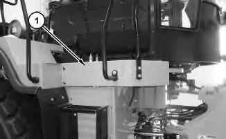
Illustration 1 g02283955
2. Use two people in order to remove platform (1).
3. Disconnect tube assembly (2), harness assemblies (5), and hose assemblies (3). Remove control valve (4).
1. Install control valve (4) in the reverse order of the removal.
Copyright 1993 - 2023 Caterpillar Inc. All Rights Reserved. Private Network For SIS Licensees. Mon Feb 27 22:33:59 UTC+0530 2023
Product: WHEEL LOADER
Model: 972K WHEEL LOADER Z4W
Configuration: 972K Wheel Loader Z4W00001-UP (MACHINE) POWERED BY C9.3 Engine
Disassembly and Assembly
966K and 972K Wheel Loaders Machine Systems
Media Number -KENR5833-02
Publication Date -01/03/2011 Date Updated -09/08/2019
SMCS - 4265-016
Assembly Procedure
Table 1
Tools
Note: Cleanliness is an important factor. Before assembly, all parts should be thoroughly cleaned in cleaning fluid. Allow the parts to air dry. Wiping cloths or rags should not be used to dry parts Lint may be deposited on the parts which may cause later trouble. Inspect all parts. If any parts are worn or damaged, use new parts for replacement.
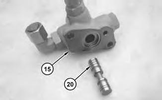
Illustration 1 g01157416
1. Install spool (20) into valve body (15).

2
2. Install O-ring seals (17) and (18).
3. Install spool (19) into valve body (2).
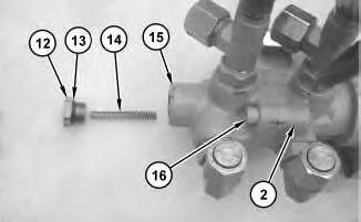
Illustration 3
Personal injury can result from being struck by parts propelled by a released spring force.
Make sure to wear all necessary protective equipment.
Follow the recommended procedure and use all recommended tooling to release the spring force.
4. Apply Tooling (A) to bolts (16). Use bolts (16) to secure valve body (15) to valve body (2).
5. Install O-ring seal (13) on plug (12).
6. Install spring (14) and plug (12) into valve body (15).

Illustration 4
7. Install shims (11) onto stop (4).
Illustration 5
8. Install seals (10) into retainer (7).
Illustration 6
9. Install plunger (9) into retainer (7).
10. Install O-ring seal (8) onto retainer (7).
7
Personal injury can result from being struck by parts propelled by a released spring force.
Make sure to wear all necessary protective equipment.
Follow the recommended procedure and use all recommended tooling to release the spring force.
11. Install spring (3), stop (4), spring (5), spring (6), and retainer (7) into valve body (2).

Illustration 8
12. Install boot (1).
End By:
a. Install the brake control valve. Refer to Disassembly and Assembly, "Brake Control Valve (Service) - Install".
Product: WHEEL LOADER
Model: 972K WHEEL LOADER Z4W
Configuration: 972K Wheel Loader Z4W00001-UP (MACHINE) POWERED BY C9.3 Engine
Disassembly and Assembly
966K and 972K Wheel Loaders Machine Systems
Media Number -KENR5833-02
Publication Date -01/03/2011 Date Updated -09/08/2019
SMCS - 4265-015
Start By:
a. Remove the brake control valve. Refer to Disassembly and Assembly, "Brake Control Valve (Service) - Remove".
Note: Cleanliness is an important factor. Before the disassembly procedure, the exterior of the component should be thoroughly cleaned. This will help to prevent dirt from entering the internal mechanism.
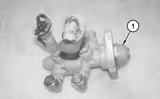
Illustration 1
1. Remove boot (1).
g01157403
2
Personal injury can result from being struck by parts propelled by a released spring force.
Make sure to wear all necessary protective equipment.
Follow the recommended procedure and use all recommended tooling to release the spring force.
2. Remove retainer (7) from valve body (2).
3. Remove spring (6), spring (5), stop (4), and spring (3) from valve body (2).
Illustration 3
4. Remove O-ring seal (8) from retainer (7).
5. Remove plunger (9) from retainer (7).
Illustration 4
6. Remove seals (10) from retainer (7).
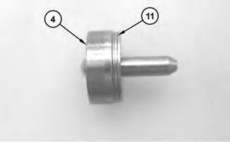
Illustration 5
7. Remove shims (11) from stop (4).
g01157412
Illustration 6
g01157413
Personal injury can result from being struck by parts propelled by a released spring force.
Make sure to wear all necessary protective equipment.
Follow the recommended procedure and use all recommended tooling to release the spring force.
8. Remove plug (12), O-ring seal (13), and spring (14) from valve body (15).
9. Remove bolts (16) in order to separate valve body (15) from valve body (2).
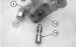
Illustration 7
10. Remove O-ring seals (17) and (18) from valve body (2).
11. Remove spool (19) from valve body (2).
Illustration 8
12. Remove spool (20) from valve body (15).
g01157416
Copyright 1993 - 2023 Caterpillar Inc. All Rights Reserved. Private Network For SIS Licensees.
Mon Feb 27 22:33:21 UTC+0530 2023
Product: WHEEL LOADER
Model: 972K WHEEL LOADER Z4W
Configuration: 972K Wheel Loader Z4W00001-UP (MACHINE) POWERED BY C9.3 Engine
Disassembly and Assembly
966K and 972K Wheel Loaders Machine Systems
Media Number -KENR5833-02
Publication Date -01/03/2011 Date Updated -09/08/2019
SMCS - 4265-010
Removal Procedure
Start By:
a. Release system pressure.
b. Hydraulic Tank Oil - Retain
Personal injury can result from hydraulic oil pressure and hot oil.
Hydraulic oil pressure can remain in the hydraulic system after the engine has been stopped. Serious injury can be caused if this pressure is not released before any service is done on the hydraulic system.
Make sure all of the work tools have been lowered to the ground, and the oil is cool before removing any components or lines. Remove the oil filler cap only when the engine is stopped, and the filler cap is cool enough to touch with your bare hand.
This is the sample of the manual click on the download link for complete manual
For some reason if link does not work download this pdf and then click