
Note: Use Bookmarks panel to navigate
This is the sample of the manual click on the download link for complete manual
Note: Use Bookmarks panel to navigate
This is the sample of the manual click on the download link for complete manual
For some reason if link does not work download this pdf and then click

Product: WHEEL LOADER
Model: 966M WHEEL LOADER LMM
Configuration: 966M Wheel Loader LMM00001-UP (MACHINE) POWERED BY C9.3 Engine
Disassembly and Assembly
966M, 966M Series XE, 972M and 972M Series XE Wheel Loaders
SMCS - 4331-010; 5077-010
S/N - A8P1-UP
S/N - B8P1-UP
S/N - DYC1-UP
S/N - EDW1-UP
S/N - EJA1-UP
S/N - FL21-UP
S/N - GGN1-UP
S/N - JPR1-UP
S/N - KJP1-UP
S/N - L9S1-UP
S/N - LMM1-UP
S/N - LSJ1-UP
S/N - M5S1-UP
S/N - P6C1-UP
Removal Procedure
Start By:
a. Connect the steering frame lock
b. release the system hydraulic pressure.
c. Retain the hydraulic tank oil.
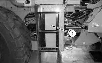
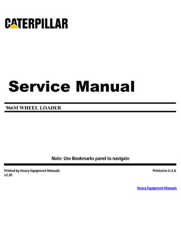
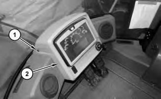
Illustration 1
1. Remove the bolts and open door (1).
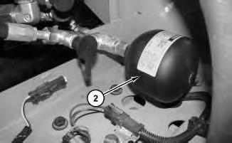
Illustration 2
2. Remove steering and pilot oil accumulator (2).
3. Remove O-ring seal (3) from steering and pilot oil accumulator (2).
1. Install steering and pilot oil accumulator (2) in the reverse order of removal.
Copyright 1993 - 2025 Caterpillar Inc. All Rights Reserved. Private Network For SIS Licensees.
Wed May 7 09:54:48 UTC+0530 2025
Product: WHEEL LOADER
Model: 966M WHEEL LOADER LMM
Configuration: 966M Wheel Loader LMM00001-UP (MACHINE) POWERED BY C9.3 Engine
Disassembly and Assembly
966M, 966M Series XE, 972M and 972M Series XE Wheel Loaders Media
SMCS - 7304-010-FM; 7309-010-FM; 7309-011-FM; 7311-010-FM; 7320-010-FM
S/N - A8P1-UP
S/N - B8P1-UP
S/N - DYC1-UP
S/N - EDW1-UP
S/N - EJA1-UP
S/N - FL21-UP
S/N - GGN1-UP
S/N - JPR1-UP
S/N - KJP1-UP
S/N - L9S1-UP
S/N - LMM1-UP
S/N - LSJ1-UP
S/N - M5S1-UP
S/N - P6C1-UP
Removal Procedure
Start By:
a. Remove the seat.
1
1. Remove four screws (1) and lower display assembly (2) out of the way.
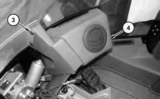
2
2. Remove eight screws (3) and air duct (4).
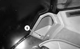
3
3. Remove screw (5).
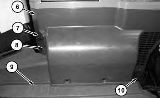
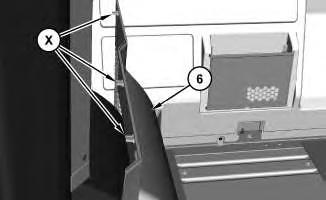
4. Remove holder (10). Remove four screws (8). Fold floor mat (9) out of the way. Carefully remove panel (6). There are three locking tabs (X) at the top on the opposite side of panel (6). Disconnect the harness assembly for auxiliary power port (7).
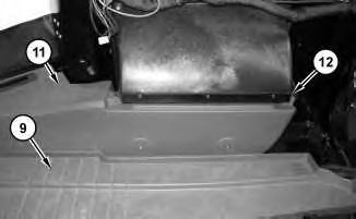
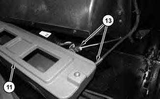
5. Remove two screws (12). Fold floor mat (9) back and slide duct (11) out in order to disconnect harness assemblies (13). Remove air duct (11).
8
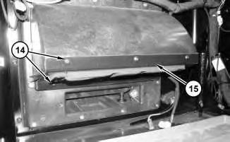
6. Remove six screws (14) and lower blower motor support bracket (15).
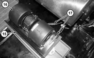
9
7. Disconnect harness assemblies (17). Separate blower motor (16) from blower motor support bracket (15).
1. Install blower motor (16) in the reverse order of the removal.
Copyright 1993 - 2025 Caterpillar Inc. All Rights Reserved. Private Network For SIS Licensees.
Wed May 7 10:41:42 UTC+0530 2025
Product: WHEEL LOADER
Model: 966M WHEEL LOADER LMM
Configuration: 966M Wheel Loader LMM00001-UP (MACHINE) POWERED BY C9.3 Engine
Disassembly and Assembly
966M, 966M Series XE, 972M and 972M Series XE Wheel Loaders
Media Number -UENR5562-07
SMCS - 4263-016
S/N - A8P1-UP
S/N - B8P1-UP
S/N - DYC1-UP
S/N - EDW1-UP
S/N - EJA1-UP
S/N - FL21-UP
S/N - GGN1-UP
S/N - JPR1-UP
S/N - KJP1-UP
S/N - L9S1-UP
S/N - LMM1-UP
S/N - LSJ1-UP
S/N - M5S1-UP
S/N - P6C1-UP
Table 1
-23/02/2018
i05223496
1
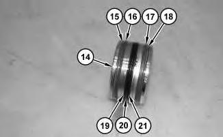
1. Install seals (21), (20), (19), (18), (17), (16), and (15) to piston (14).
2
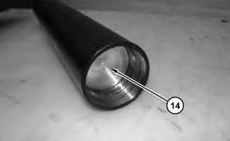
Install piston (14).
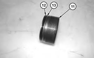
Illustration 3
g03338249
3. Install backup ring (13) and O-ring seal (12) to end cap (11).
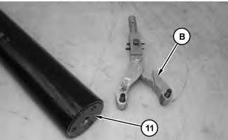
Illustration 4
g03338241
4. Use Tooling (B) in order to install end cap (11). Tighten end cap (11) to a torque of 122 ± 10 N·m (90 ± 7 lb ft).

Illustration 5
5. Install the O-ring seal and fitting (10).
g03338209
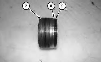
Illustration 6
6. Install backup ring (8) and O-ring seal (9) to end cap (7).
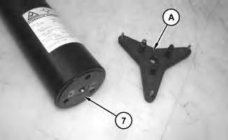
Illustration 7
g03338126
7. Use Tooling (A) in order to install end cap (7). Tighten end cap (7) to a torque of 122 ± 10 N·m (90 ± 7 lb ft).
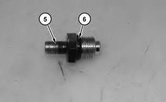
Illustration 8
8. Install O-ring seal (6) to valve (5).
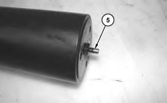
Illustration 9
g03338102
9. Install valve (5). Tighten valve (5) to a torque of 35.0 ± 1.5 N·m (25.81 ± 1.11 lb ft).
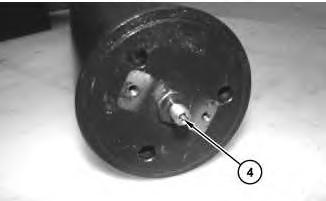
Illustration 10
10. Install schrader valve (4).
g03338090
11. Charge the accumulator. Refer to Special Instruction, "Accumulator Discharging and Charging Procedures" for the proper procedure.
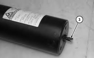
Illustration 11
g03338088
12. Install valve cap (3). Tighten valve cap (3) to a torque of 1.6 ± 1.0 N·m (14.16 ± 8.85 lb in).
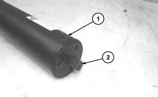
Illustration 12 g03338076
13. Install protector (2) to brake accumulator (1).
14. Repeat Steps 1 through 13 for the remaining brake accumulator.
End By:
a. Install the brake accumulator.
Copyright 1993 - 2025 Caterpillar Inc. All Rights Reserved. Private Network For SIS Licensees.
Wed May 7 10:09:37 UTC+0530 2025
Product: WHEEL LOADER
Model: 966M WHEEL LOADER LMM
Configuration: 966M Wheel Loader LMM00001-UP (MACHINE) POWERED BY C9.3 Engine
Disassembly and Assembly
966M, 966M Series XE, 972M and 972M Series XE Wheel Loaders
SMCS - 4263-015
S/N - A8P1-UP
S/N - B8P1-UP
S/N - DYC1-UP
S/N - EDW1-UP
S/N - EJA1-UP
S/N - FL21-UP
S/N - GGN1-UP
S/N - JPR1-UP
S/N - KJP1-UP
S/N - L9S1-UP
S/N - LMM1-UP
S/N - LSJ1-UP
S/N - M5S1-UP
S/N - P6C1-UP
Table 1
i05221999
Start By:
a. Remove the brake accumulator.
The accumulator is filled with dry nitrogen. Sudden release of nitrogen pressure can cause personal injury.
To avoid personal injury, release the nitrogen pressure from the accumulator before disassembly.
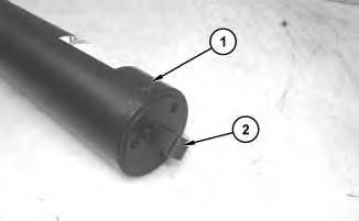
Illustration 1
1. Remove protector (2) from brake accumulator (1).
2
2. Remove valve cap (3).
3. Discharge the accumulator. Refer to Special Instruction, "Accumulator Discharging and Charging Procedures" for the proper procedure.
Illustration 3
4. Remove schrader valve (4).
g03338090
Illustration 4
5. Remove valve (5).
g03338102
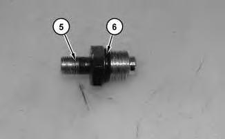
Illustration 5
6. Remove O-ring seal (6) from valve (5).
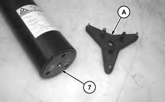
Illustration 6
g03338126
7. Use Tooling (A) in order to remove end cap (7).

Illustration 7
g03338202
8. Remove O-ring seal (9) and backup ring (8) from end cap (7).
Illustration 8
9. Remove fitting (10) and the O-ring seal.
g03338209
Illustration 9
g03338241
10. Use Tooling (B) in order to remove end cap (11).
Illustration 10
g03338249
11. Remove O-ring seal (12) and backup ring (13) from end cap (11).

Illustration 11
12. Remove piston (14).
g03338262
Illustration 12
g03338263
13. Remove seals (15), (16), (17), (18), (19), (20), and (21) from piston (14).
14. Repeat Steps 1 through 13 for the remaining brake accumulator.
Copyright 1993 - 2025 Caterpillar Inc. All Rights Reserved. Private Network For SIS Licensees. Wed May 7 10:09:19 UTC+0530 2025
Product: WHEEL LOADER
Model: 966M WHEEL LOADER LMM
Configuration: 966M Wheel Loader LMM00001-UP (MACHINE) POWERED BY C9.3 Engine
Disassembly and Assembly
966M, 966M Series XE, 972M and 972M Series XE Wheel Loaders
SMCS - 4263-010
S/N - A8P1-UP
S/N - B8P1-UP
S/N - DYC1-UP
S/N - EDW1-UP
S/N - EJA1-UP
S/N - FL21-UP
S/N - GGN1-UP
S/N - JPR1-UP
S/N - KJP1-UP
S/N - L9S1-UP
S/N - LMM1-UP
S/N - LSJ1-UP
S/N - M5S1-UP
S/N - P6C1-UP
Removal Procedure
Start By:
i05221803
a. Connect the steering frame lock.
b. Release the system hydraulic pressure.
c. Retain the hydraulic tank oil.
1
1. Remove the bolts and open door (1).
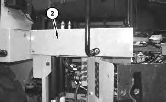
2
2. Remove platform (2).
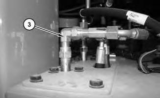
Illustration 3
3. Disconnect hose assembly (3).
g03337991
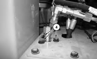
Illustration 4
4. Remove bolts (4).
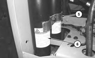
Illustration 5
g03338003
5. Remove clamp (5) and remove brake accumulator (6).
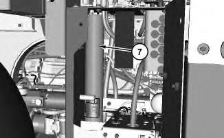
6
g03338028
This is the sample of the manual click on the download link for complete manual
For some reason if link does not work download this pdf and then click