DOWNLOAD LINK
For some reason if link does not work download this pdf and then click
Illustration 4
4. Install shaft (20) in order to attach toggle assembly (21) to scissor assembly (11). Tighten the two nuts for shaft (20) to a torque of 15 ± 3 N·m (11 ± 2 lb ft).
Illustration 5
g00872031
5. Install shaft assemblies (19) in order to attach tether straps (11A) and scissor assembly (11) to housing assembly (14). Tighten the nuts on shaft assemblies (19) to a torque of 20 ± 5 N·m (15 ± 4 lb ft). Install blocking in order to prevent scissor assembly (11) from falling.
Illustration 6
g00872029
g00872037
7
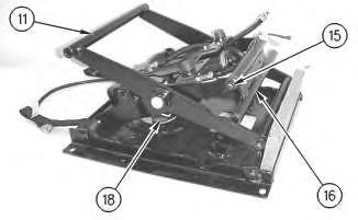
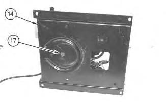
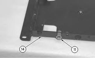
6. Install screw (17) in order to attach housing assembly (14) to spring assembly (18).
7. Install shaft (15) in order to attach toggle assembly (16) to scissor assembly (11). Tighten the two nuts for shaft (15) to a torque of 15 ± 3 N·m (11 ± 2 lb ft).
8 g00897454
Illustration
Illustration
9
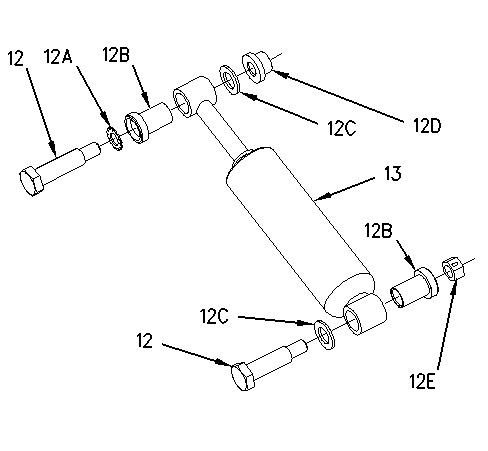
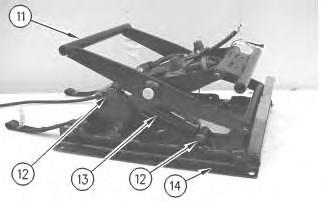
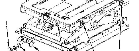
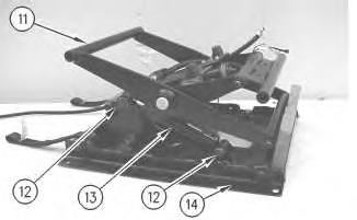
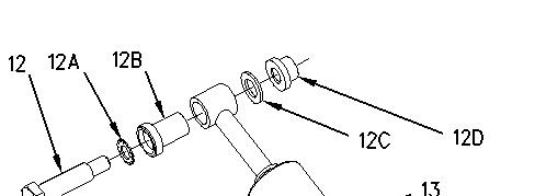
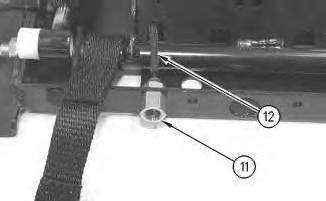
8. Install bearings (12B) to shock absorber (13).
9. Install bolts (12) in order to attach shock absorber (13) to scissor assembly (11) and housing assembly (14). Remove the blocking.
Note: Illustration 8 shows the location of lockwasher (12A), bearings (12B), washers (12C), nut (12D), and locknut (12E).
10. Repeat Steps 8 and 9 if the seat is equipped with a shock absorber on the opposite side.
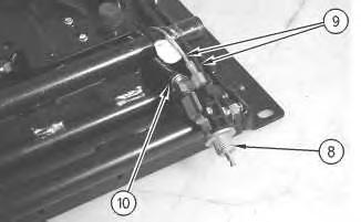
Illustration 10
g00871994
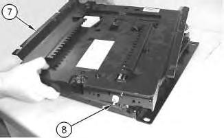
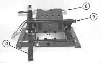
11. Connect harness assemblies (9) and hose assembly (10) to air valve (8).
Illustration
g00872007
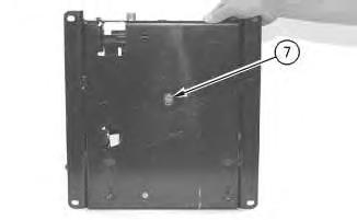
Illustration 11 g00871971
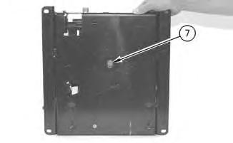
12. Position air valve (8) to upper housing assembly (7). Position upper housing assembly (7) to the seat.
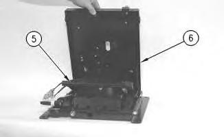
Illustration 12 g00871951
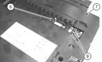
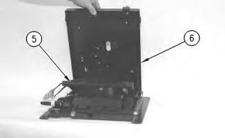
13. Install cable strap (6) in order to secure harness assemblies (9) to upper housing assembly (7).
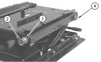
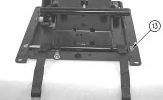
Illustration 13 g00876043
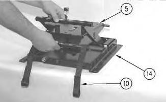
14. Install shaft assemblies (5). Tighten the nuts for shaft assemblies (5) to a torque of 20 ± 5 N·m (15 ± 4 lb ft).
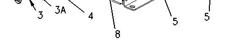
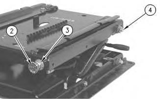
15. Position plate (4) to the seat. Install lockwasher (3A) and nut (3) in order to secure air valve (8) to the seat. Tighten the setscrew in adjustment knob (1) in order to secure adjustment knob (1) to air valve (8).
Illustration 14
16. Install boot (2) to the seat.
1993 - 2024 Caterpillar Inc.
Rights Reserved.
g00871915
Network For SIS Licensees. Fri Dec 20 12:41:08 UTC+0530 2024
Product: WHEEL LOADER
Model: 966H WHEEL LOADER A6J
Configuration: 966H WHEEL LOADER A6J00001-01800 (MACHINE) POWERED BY C11 ENGINE
Disassembly and Assembly
Comfort Series Seat For Caterpillar Machines
Media Number -RENR2165-12 Publication Date -01/10/2013 Date Updated -31/10/2013
Air Suspension with Air Valve Knob Height Adjustment
Disassemble
SMCS - 7324-015-AJ
Disassembly Procedure
The air spring of the air suspension is filled with air pressure.
Prior to disassembly, release the air pressure in the air spring. Failure to do so could result in personal injury.
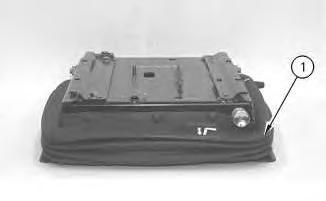
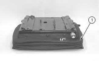
Illustration 1 g00871915
1. Pull adjustment knob (1) in order to release the air from the seat.
i01693748
2. Remove boot (2).
Illustration 2 g00876043
3. Loosen the setscrew in adjustment knob (1) and remove adjustment knob (1). Remove nut (3) and lockwasher (3A). Remove plate (4) from air valve (8).
4. Remove shaft assemblies (5).
Illustration 3 g00871951
5. Remove cable strap (6) in order to disconnect harness assemblies (9) from upper housing assembly (7).
Illustration 4
g00871971
6. Lift upper hou3ing assembly (7) and push air valve (8) away from upper housing assembly (7). Remove upper housing assembly (7).
Illustration 5
g00871994
7. Disconnect harness assemblies (9) and hose assembly (10) from air valve (8).
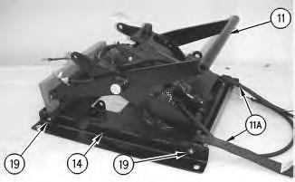
Illustration 6
g00872007
Illustration 7 g00897454
8. Raise scissor assembly (11) and install blocking in order to prevent scissor assembly (11) from falling.
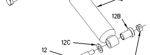
9. Remove bolts (12) in order to remove shock absorber (13) from scissor assembly (11) and housing assembly (14).
10. Remove bearings (12B) from shock absorber (13).
Note: Illustration 7 shows the location of lockwasher (12A), bearings (12B), washers (12C), nut (12D), and locknut (12E).
11. Repeat Steps 9 and 10 if the seat is equipped with a shock absorber on the opposite side.
Illustration 8
Illustration 9
g00872029
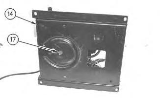
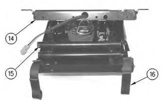
12. Remove shaft (15) in order to remove toggle assembly (16) from scissor assembly (11).
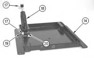
13. Remove screw (17) in order to disconnect spring assembly (18) from housing assembly (14).
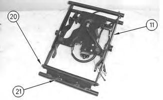
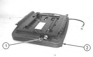
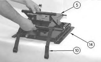
Illustration 10
g00872031
14. Remove shaft assemblies (19) in order to remove scissor assembly (11) from housing assembly (14) and tether straps (11A).
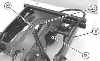
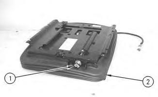
Illustration 11
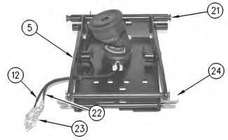
15. Remove shaft (20) in order to remove toggle assembly (21) from scissor assembly (11).
12
Personal injury can result from being struck by parts propelled by a released spring force.
Make sure to wear all necessary protective equipment.
Follow the recommended procedure and use all recommended tooling to release the spring force.
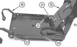
16. Remove hose assembly (22) and bolt (23) in order to remove spring assembly (18) from scissor assembly (11).
13
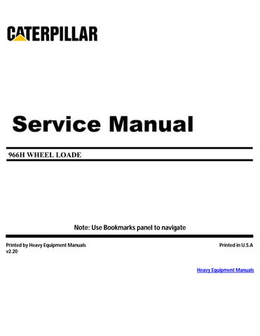
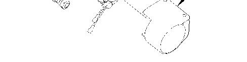
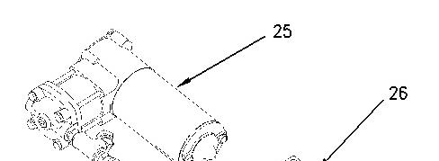
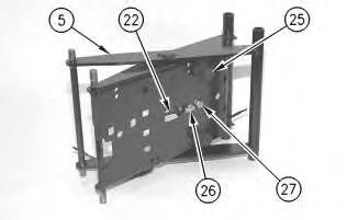
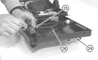
17. Remove bolts (24) in order to remove compressor assembly (25) from scissor assembly (11).
Illustration
g00872043
Illustration
g00872046
Illustration 14 g00891451
18. Remove compressor assembly (25) from mount (26).
Copyright 1993 - 2024 Caterpillar Inc. All Rights Reserved. Private Network For SIS Licensees.
Fri Dec 20 12:40:49 UTC+0530 2024
Product: WHEEL LOADER
Model: 966H WHEEL LOADER A6J
Configuration: 966H WHEEL LOADER A6J00001-01800 (MACHINE) POWERED BY C11 ENGINE
Disassembly and Assembly
Comfort Series Seat For Caterpillar Machines
Media Number -RENR2165-12
Air Suspension With System Air - Assemble
SMCS - 7324-016-AJ
Assembly Procedure
Table 1 Tools Needed
- Loctite LB 8632 Silicone Lubricant (1)
- Loctite LB 8104 Silicone Lubricant (2)
- Loctite LB 8801 Silicone Lubricant (3)
- Loctite LB Superlube (4)
(1) North America (2) EAME (3) Asia Pacific Division (4) South America
-31/10/2013
1. Check the condition of all parts of the air suspension. If any of the parts are worn or damaged, install new parts.
i07432502
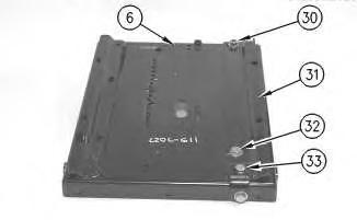
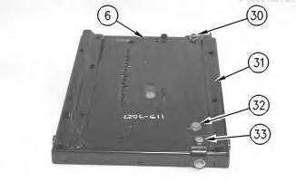
Illustration 1
Typical Example
g00275862
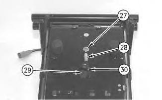
2. Position slider track (31) on upper housing (6). Install bolt (33), two bolts (32) and the washers. Tighten bolts (33) and (32) to a torque of 30 ± 7 N·m (22 ± 5 lb ft). Install locknut (30) and the washer. Tighten locknut (30) to a torque of 40 ± 8 N·m (30 ± 6 lb ft).
Illustration 2
g00275860
Illustration 3
g00275858
3. Position air spring (28) on scissor assembly (5). Apply Tooling (A) to the threads of bolt (27). Install bolt (27) that holds the air spring to scissor assembly (5). Tighten bolt (27) to a torque of 40 ± 8 N·m (30 ± 6 lb ft).
4. Position tubes (12) and (22) on scissor assembly (5). Install new tie-wraps (29) to secure the tubes to the scissor assembly.
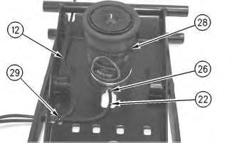
5. Connect tube (22) to fitting (26) on air spring (28). Install two bumpers (25).
Illustration 4
g00275857
6. Apply Tooling (B) to scissor assembly (5) at the point of installation for two rollers (24). Install two rollers (24) and two bearings (21). Connect tubes (12) and (22) to valve assembly (23).
Illustration 5
7. Install fitting (11) in lower housing (14).
g00275856
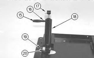
Illustration 6
Typical Example
g00275855
8. Install two bearings (17) and (20), damper (18), the pin and locknut (19). Tighten locknut (19) to a torque of 30 ± 7 N·m (22 ± 5 lb ft). Install shaft (7) and cap (15) on damper (18).
Illustration 7
g00275854
9. Install scissor assembly (5) into lower housing (14). Install two tether belts (10).
Illustration 8
g00275851
10. Install the lower shaft assembly. Install locknut (13) and the lock washer. Tighten locknut (13) to a torque of 40 ± 8 N·m (30 ± 6 lb ft).
Illustration 9
11. Connect tube (12) to fitting (11).
g00275850
Illustration 10
Typical Example
g00275849
12. Install two tether belts (10) and two bearings (9). Apply Tooling (B) to the scissor assembly at the point of installation for rollers (8). Install rollers (8) on the scissor assembly.
Illustration 11
g00275848
13. Apply Tooling (A) to the threads of screw (7). Install screw (7) to secure the air spring, which is not shown. Tighten the screw to a torque of 4.3 ± 1 N·m (38 ± 9 lb in).
Illustration 12
14. Install upper housing (6) on scissor assembly (5).
Illustration 13
Typical Example
g00275845
15. Install the upper shaft assembly, locknut (4), and the lock washer. Tighten the locknut to a torque of 40 ± 8 N·m (30 ± 6 lb ft). Install locknut (4) and the lock washer. Apply Tooling (A) to the setscrew of knob (2). Install knob (2) and the setscrew.
Illustration 14
Typical Example
g00275844
g00275846
Install boot (1).
17. Install the seat on the air suspension. Install the seat in the machine.
Copyright 1993 - 2024 Caterpillar Inc. All Rights Reserved. Private Network For SIS Licensees.
Fri Dec 20 12:42:02 UTC+0530 2024
Product: WHEEL LOADER
Model: 966H WHEEL LOADER A6J
Configuration: 966H WHEEL LOADER A6J00001-01800 (MACHINE) POWERED BY C11 ENGINE
Disassembly and Assembly
Comfort Series Seat For Caterpillar Machines
Media Number -RENR2165-12 Publication Date -01/10/2013 Date Updated -31/10/2013
Air Suspension With System Air - Disassemble
SMCS - 7324-015-AJ
Disassembly Procedure
1. Remove the seat from the machine. Separate the seat from the air suspension.
Illustration 1
Typical Example
2. Remove boot (1).
g00275844
i01518481
Illustration 2
Typical Example
g00275845
3. Loosen the setscrew on knob (2) and remove the knob. Remove nut (3) and the lock washer.
4. Remove locknut (4) and the lock washer. Remove the upper shaft assembly.
Illustration 3
g00275846
5. Tilt upper housing (6) forward. Slide the upper housing off scissor assembly (7).
Illustration 4
g00275848
6. Remove screw (7) from the air spring, which is not shown.
Illustration 5
g00275849
7. Disconnect two tether belts (10). Remove two bearings (9) and two rollers (9).
Illustration 6
8. Disconnect tube (12) from fitting (11).
g00275850
Illustration 7
g00275851
9. Remove locknut (13) and the lock washer. Remove the lower shaft assembly.
8
10. Remove two tether belts (10). Lift up scissor assembly (5) and slide the scissor assembly out of lower housing (14).
Illustration 9
Typical Example
11. Remove cap (15) and shaft (16) from damper (18). Remove locknut (19), the pin, bearings (17) and (20), and damper (18).
Illustration 10
12. Remove fitting (11) from lower housing (14).
Illustration
g00275854
g00275855
g00275856
Illustration 11
13. Remove two bearings (21) and two rollers (24) from scissor assembly (5). Disconnect tubes (22) and (12) from valve assembly (23).
Illustration 12
g00275858
Illustration 13
g00275860
14. Remove two bumpers (25). Remove bolt (27) from air spring (28).
15. Disconnect tube (22) from fitting (26). Remove air spring (28) from scissor assembly (5).
16. Cut tie-wraps (29) that are holding tubes (22) and (12) to scissor assembly (5).
g00275857
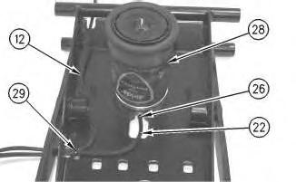
Illustration 14
Typical Example
g00275862
17. Remove two bolts (32) and the washers. Remove locknut (30) and the washer. Remove bolt (33). Remove slider track (31) from upper housing (6).
Copyright 1993 - 2024 Caterpillar Inc. All Rights Reserved.
Private Network For SIS Licensees. Fri Dec 20 12:41:36 UTC+0530 2024
Product: WHEEL LOADER
Model: 966H WHEEL LOADER A6J
Configuration: 966H WHEEL LOADER A6J00001-01800 (MACHINE) POWERED BY C11 ENGINE
Disassembly and Assembly
Comfort Series Seat For Caterpillar Machines
Media Number -RENR2165-12 Publication Date -01/10/2013 Date Updated -31/10/2013
Air Suspension With Toggle Switch Height Adjustment -
Assemble
SMCS - 7324-016-AJ
Assembly Procedure
Table 1
A - Loctite 243
- Loctite LB 8632 Silicone Lubricant (1)
- Loctite LB 8104 Silicone Lubricant (2)
- Loctite LB 8801 Silicone Lubricant (3)
- Loctite LB Superlube (4)
(1) North America (2) EAME (3) Asia Pacific Division (4) South America
1. Check the condition of all parts of the air suspension. If any of the parts are worn or damaged, install new parts.
i07432503
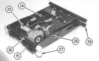
1
2. Install two rubber bumpers (34). Apply Tooling (B) to the scissor assembly at the point of installation for four rollers (37). Install four bushings (39) and four rollers (37).
3. Position air compressor (35) in scissor assembly (15). Install clamp (36) and tie-wrap (38) to secure air compressor (35) to the scissor assembly. Tighten clamp (36) to a torque of 3.2 ± 0.6 N·m (29 ± 5 lb in).
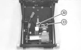
Illustration 2
g00275786
4. Connect tube (30) to fitting (33). Make sure that the tube is securely seated in the fitting.
Illustration 3
g00275785
Illustration
g00275788
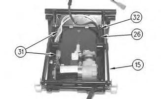
5. Position wiring harness (26). Connect two electrical connectors (31) in the original positions. Install tie-wraps (32) to secure wiring harness (26) to scissor assembly (15).
Illustration 4
g00275783
6. Connect tube (30) to fitting (28). Make sure that the tube is securely seated in the fitting. Apply Tooling (A) to the threads of bolt (27). Position air spring (29) on the scissor assembly. Install bolt (27) to secure air spring (29). Tighten bolt (27) to a torque of 4.3 ± 1 N·m (38 ± 9 lb in).
Illustration 5
g00275782
7. Install wiring harness connection (25) and the washer in upper housing (24). Install new tiewraps on wiring harness (26) to secure the wiring harness to the upper housing.
Illustration 6 g00275780
8. Install scissor assembly (15) in upper housing (24) by sliding rollers (21) into the slider track. Slide bumper (22) into the slider track to secure the scissor assembly. Install two tether belts (16), bolts (23) and the locknuts in upper housing (24). Tighten bolts (23) to a torque of 40 ± 8 N·m (30 ± 6 lb ft).
Illustration 7
g00275778
9. Install two bearings (17), damper (18), pin (20) and nut (10) into lower housing (14). Tighten nut (19) to a torque of 40 ± 8 N·m (30 ± 6 lb ft).
Illustration 8
g00275777
10. Install scissor assembly (15) into lower housing (14). Connect the damper and two tether belts (16) to lower housing (14).
This is the sample of the manual click on the download link for complete manual