DOWNLOAD LINK
For some reason if link does not work download this pdf and then click
2
3
Illustration
g01075180
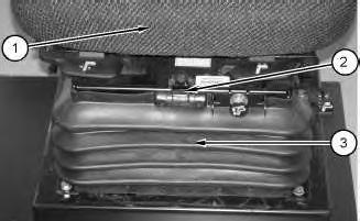
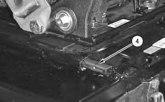
4. Remove bolts (4). Remove cover (5) .
Illustration
g01075181
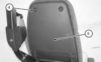
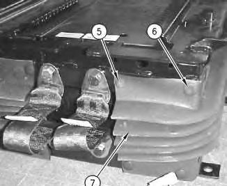
5. Remove bolt (9) and retainer (8). Remove nuts (7). Remove armrest (6) .
Illustration 4
g01075238
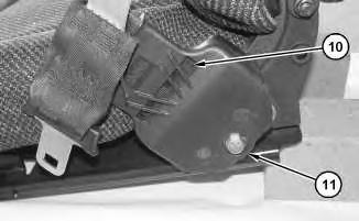
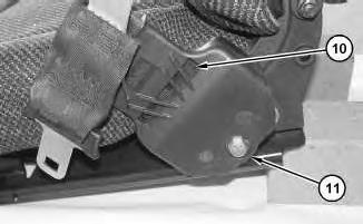
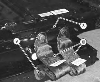
6. Remove bolt (11) and the spacer from belt assembly (10) .
Illustration 5
g01075241
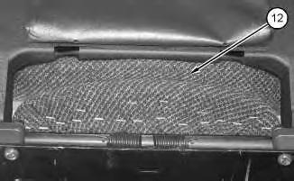
7. Use a prybar in order to remove the bottom of seat cushion (12) .
Illustration 6
g01075244
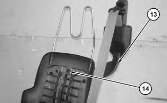
8. Remove nuts (14) and the bolts. Remove support assembly (13) .
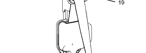
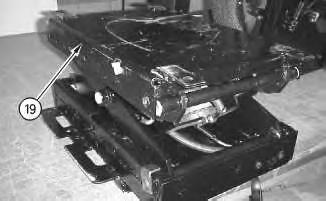
Illustration 7 g01109929
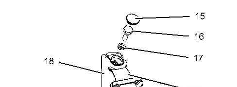
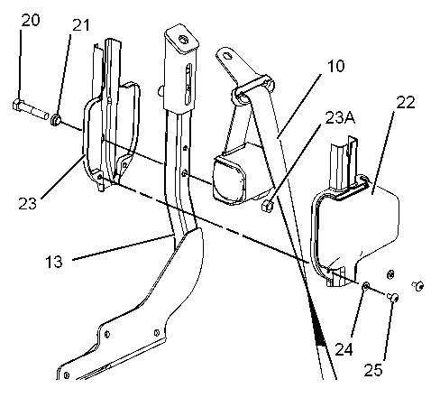
9. Remove plug (15) from cover (18). Remove bolt (16), and spacer (17) in order to release buckle (19) from support assembly (13). Remove cover (18) from support assembly (13) .
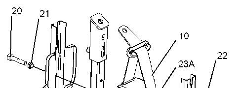
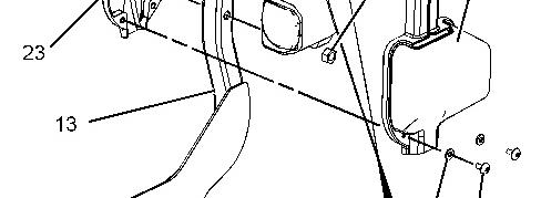
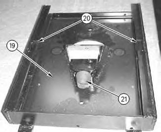
Illustration 8 g01109940
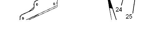
10. Remove screws (25) and washers (24) in order to remove cover (22) from support assembly (13) .
11. Remove nut (23A), bolt (20), and spacer (21) in order to remove cover (23) and belt assembly (10) from support assembly (13) .
9 g01109962
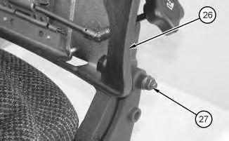
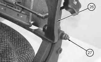
12. Remove nut (27) and the bolt. Remove backrest (26) .
Illustration
Personal injury can result from being struck by parts propelled by a released spring force.
Make sure to wear all necessary protective equipment.
Follow the recommended procedure and use all recommended tooling to release the spring force.
Illustration 10
g01109965
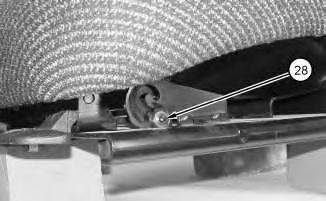
13. Remove rod (28) .
Illustration 11
g01109967
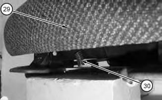
14. Remove spring (30). Remove cushion (29) .
12
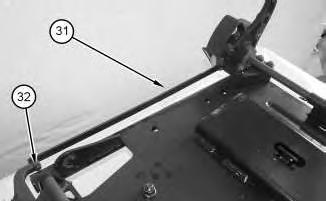
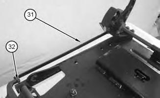
15. Remove cotter pins (32). Remove bar (31) .
Illustration 13
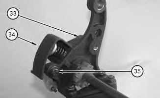
16. Remove bolts (33) and (35). Remove bracket (34) .
Illustration 14
Illustration
g01109968
g01109973
g01109975
Personal injury can result from being struck by parts propelled by a released spring force.
Make sure to wear all necessary protective equipment.
Follow the recommended procedure and use all recommended tooling to release the spring force.
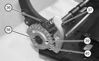
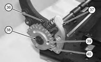
17. Spring (36) is under compression. Remove pawl (37) and spring (36). Remove bolt (38) and washer (39). Use a prybar in order to remove gear (40) .
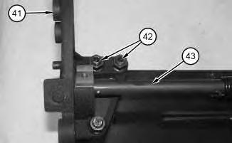
18. Remove nuts (42) and the bolts. Remove the nuts and the bolts on the opposite side. Remove bracket (41). Remove shaft assembly (43) .
Illustration 15
g01109979
Illustration 16
g01109981
Personal injury can result from being struck by parts propelled by a released spring force.
Make sure to wear all necessary protective equipment.
Follow the recommended procedure and use all recommended tooling to release the spring force.
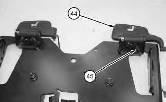
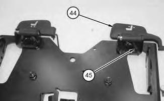
19. Remove springs (45). Remove handle (44) .
Personal injury can result from being struck by parts propelled by a released spring force.
Make sure to wear all necessary protective equipment.
Follow the recommended procedure and use all recommended tooling to release the spring force.
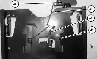
20. Remove springs (48) and rods (47) from latches (49). Remove handle (46) .
Illustration 17
g01109983
18
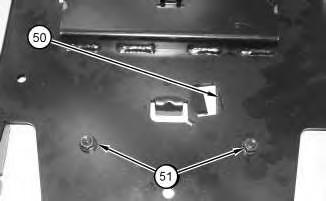
21. Remove nuts (51). Remove latches (50) .
Copyright 1993 - 2022 Caterpillar Inc.
All Rights Reserved.
Private Network For SIS Licensees.
Wed Dec 21 19:33:28 UTC+0530 2022
Illustration
Product: WHEEL LOADER
Model: 966G II WHEEL LOADER ANZ
Configuration: 966G II Wheel Loader ANZ00001-UP (MACHINE) POWERED BY 3176C Engine
Disassembly and Assembly
Comfort Series Seat For Caterpillar Machines
Media Number -RENR2165-12
Publication Date -01/10/2013 Date Updated -31/10/2013
Comfort Seat with Front Controls - Assemble
SMCS - 7324-016
Assembly Procedure
Install latches (50). Install nuts (51) .
i02140417
Illustration 1
g01109987
1.
Personal injury can result from being struck by parts propelled by a released spring force.
Make sure to wear all necessary protective equipment.
Follow the recommended procedure and use all recommended tooling to release the spring force.
2. Install handles (46). Install rods (47) and springs (48) onto latches (49) .
3
Illustration 2
g01109983
Illustration
g01109981
Personal injury can result from being struck by parts propelled by a released spring force.
Make sure to wear all necessary protective equipment.
Follow the recommended procedure and use all recommended tooling to release the spring force.
3. Install handle (44). Install springs (45) .
4
4. Install shaft assembly (43). Install bracket (41). Install the bolts and nuts (42). Install the bolts and the nuts for the opposite side.
5
5. Install gear (40). Install washer (39) and bolt (38). Install pawl (37). Install spring (36) .
Note: Spring (36) will be under compression.
Illustration
g01109979
Illustration
g01109975
6
6. Install bracket (34) into position. Install bolts (33) and (35) .
7
7. Install bar (31). Install cotter pins (32) .
8
Illustration
g01109973
Illustration
g01109968
Illustration
g01109967
Personal injury can result from being struck by parts propelled by a released spring force.
Make sure to wear all necessary protective equipment.
Follow the recommended procedure and use all recommended tooling to release the spring force.
8. Install cushion (29). Install spring (30) .
Illustration 9
g01109965
9. Install rod (28) .
Illustration 10
g01109962
Illustration 11
10. Install backrest (26). The front tooth that is on the leg of backrest (26) should engage the first tooth of the side gears, as shown. Install the bolt and nut (27) .
Illustration 12 g01109940
11. Position belt assembly (10) and cover (23) to support assembly (13). Install spacer (21), bolt (20), and nut (23A) .
12. Position cover (22) and install washers (24) and screws (25) to support assembly (13) .
g00608187
Illustration 13 g01109929
13. Install cover (18) to support assembly (13). Position buckle (19) and install spacer (17) and bolt (16) to support assembly (13). Install plug (15) to cover (18) .
14
g01075244
14. Install support assembly (13). Install the bolts and nuts (14) .
Illustration
15
15. Install the bottom of seat cushion (12) so that the bottom of seat cushion (12) snaps into the bottom of the seat back.
16
16. Install bolt (11) into belt assembly (10) .
Illustration
g01075241
Illustration
g01075238
17
.
18
.
Illustration
g01075181
17. Install armrest (6). Install nuts (7). Install retainer (8). Install bolt (9)
Illustration
g01075180
18. Install cover (5). Install bolts (4)
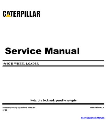
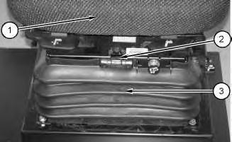
19. Install seal assembly (1) onto suspension assembly (3). Install stop bolt (2) .
20. Install the seat into the machine.
Copyright 1993 - 2022 Caterpillar Inc.
All Rights Reserved. Private Network For SIS Licensees.
Wed Dec 21 19:33:43 UTC+0530 2022
Product: WHEEL LOADER
Model: 966G II WHEEL LOADER ANZ
Configuration: 966G II Wheel Loader ANZ00001-UP (MACHINE) POWERED BY 3176C Engine
Disassembly and Assembly
Comfort Series Seat For Caterpillar Machines
Media Number -RENR2165-12
-31/10/2013
Comfort Seat with Lumbar Option and Side ControlsDisassemble
SMCS - 7324-015
Disassembly Procedure
The air spring of the air suspension is filled with air pressure.
Prior to disassembly, release the air pressure in the air spring. Failure to do so could result in personal injury.
Note: Bleed the air from the system before disassembly of the seat.
i01753929
Illustration 1
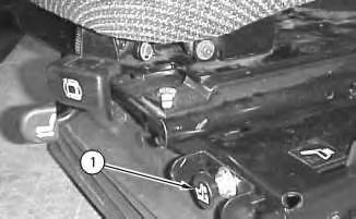
1. Pull handle (1) open. Hold handle (1) open until all of the air has been bled from the system.
Illustration 2
g00785382
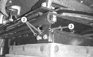
2. Remove two bolts (2) and the washers from stop block (3). Remove stop block (3) .
Illustration 3
g00785385
Note: If blocks (4) are removed, mark the locations for reassembly to the original positions on the suspension. The seat will not align properly, if the blocks are not installed to the original locations.
3. Remove the seat from the suspension. Do not remove four blocks (4) .
Illustration 4
g00785393
4. Remove acorn nut (5), fasteners (6), and boot (7) .
Illustration 5
g00785399
5. Remove bolts (9), the washers, and two straps (10) from the suspension. Remove two threaded blocks (8) from the inside of the two housing assemblies.
Illustration 6
g00786858
Illustration 7
g00785506
Illustration 8
g00785404
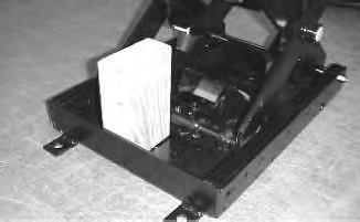
Note: A wood block may be used in order to prevent the scissors from moving during parts of the disassembly. This is especially needed when you are doing a partial disassembly of the suspension.
6. Mark the location of all cable straps for assembly purposes.
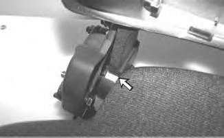
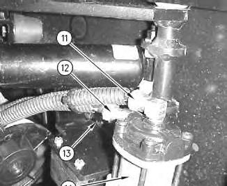
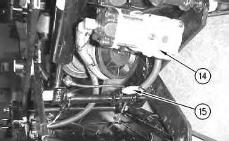
7. Disconnect hose assemblies (11) and (12) from compressor (14). Disconnect harness assembly (15) from the suspension.
8. Remove two bolts (13). Remove compressor (14) from the suspension.
Illustration 9
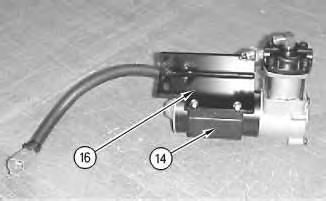
9. Remove mounting bracket (16) from compressor (14), if the compressor is being replaced.
Illustration 10
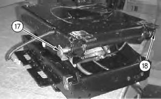
10. Remove locknut (18) (not shown), the washer, and rod (17) from the suspension.
g00785511
g00785501
11
12
11. Slide lower housing (19) in order to align slots (20). Tip lower housing (19) upward in order to remove the housing from half of the suspension. Slide lower housing (19) in order to align slots (20) for removal from the suspension.
12. Turn over the suspension. Remove the nut and the retainer in order to remove bumper (21) .
Illustration
g00785512
Illustration
g00785515
This is the sample of the manual click on the download link for complete manual