


Note: Use Bookmarks panel to navigate
This is the sample of the manual click on the download link for complete manual

Note: Use Bookmarks panel to navigate
This is the sample of the manual click on the download link for complete manual
For some reason if link does not work download this pdf and then click

Product: WHEEL LOADER
Model: 966 GC WHEEL LOADER SGW
Configuration: 966GC Wheel Loader SGW00001-UP (MACHINE) POWERED BY C9.3 Engine
Disassembly and Assembly
C9.3B Engines for Caterpillar Built Machines
Media Number -M0096470-01
Publication Date -01/12/2019
SMCS - 1054-010
Removal Procedure
Date Updated -06/12/2019
i07323723
Reference: Special Instruction, "Visual Service Procedures - Colors and Symbols" M0066576
NOTICE
Keep all parts clean from contaminants.
Contaminants may cause rapid wear and shortened component life.
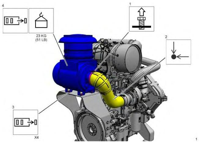
1
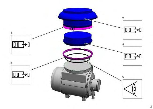
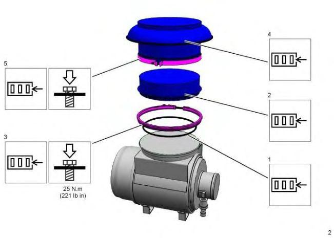
Illustration 2 g06284844
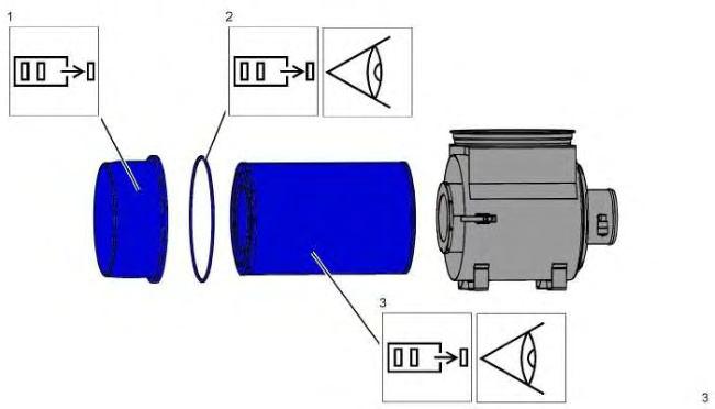
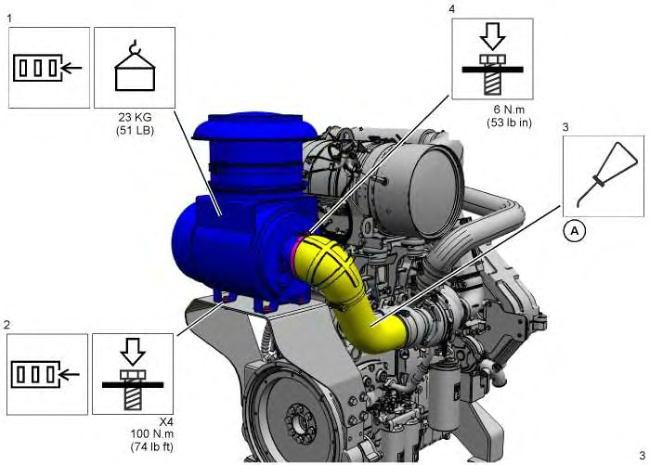
Illustration 3 g06284905
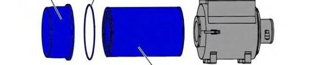
Refer to Operation and Maintenance Manual, Engine Air Cleaner Element - Replace for further information.
Table 1 Required Tools
- International Products P-80 Emulsion Rubber Assembly Lubricant 1
Keep all parts clean from contaminants.
Contaminants may cause rapid wear and shortened component life.
Note: Ensure that all components of the air cleaner and the brackets are free from wear, damage, or restriction. Replace any component that is worn, damaged, or restricted.
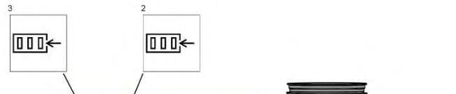

4
5 g06284941
Product: WHEEL LOADER
Model: 966 GC WHEEL LOADER SGW
Configuration: 966GC Wheel Loader SGW00001-UP (MACHINE) POWERED BY C9.3 Engine
Disassembly and Assembly
C9.3B Engines for Caterpillar Built Machines
Media Number -M0096470-01 Publication Date -01/12/2019 Date Updated -06/12/2019
SMCS - 1803-010
Removal Procedure
i06902479
Reference: Special Instruction, "Visual Service Procedures - Colors and Symbols" , M0066576
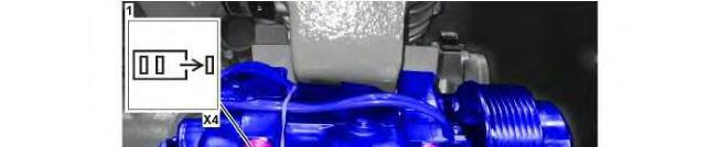


Illustration 1
Installation Procedure
Install the air compressor in the reverse order of removal.
Product: WHEEL LOADER
Model: 966 GC WHEEL LOADER SGW
Configuration: 966GC Wheel Loader SGW00001-UP (MACHINE) POWERED BY C9.3 Engine
Disassembly and Assembly
C9.3B Engines for Caterpillar Built Machines
Media Number -M0096470-01 Publication Date -01/12/2019 Date Updated -06/12/2019
i06902477
Alternator - Remove and Install
SMCS - 1405-010
Removal Procedure
Reference: Special Instruction, "Visual Service Procedures - Colors and Symbols" , M0066576
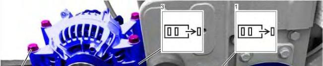
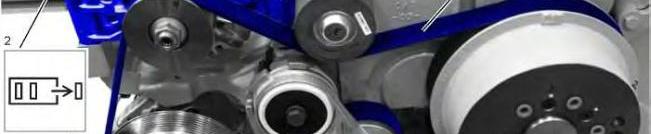

1
Install the alternator in the reverse order of removal.
Product: WHEEL LOADER
Model: 966 GC WHEEL LOADER SGW
Configuration: 966GC Wheel Loader SGW00001-UP (MACHINE) POWERED BY C9.3 Engine
Disassembly and Assembly
C9.3B Engines for Caterpillar Built Machines
Media Number -M0096470-01
Publication Date -01/12/2019
Date Updated -06/12/2019
SMCS - 1923-010
Removal Procedure
i07094655
Reference: Special Instruction, "Visual Service Procedures - Colors and Symbols" , M0066576
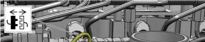
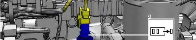

Illustration 1
Installation Procedure

Copyright 1993 - 2025 Caterpillar Inc. All Rights Reserved. Private Network For SIS Licensees. Fri Feb 21 13:06:50 UTC+0700 2025

Product: WHEEL LOADER
Model: 966 GC WHEEL LOADER SGW
Configuration: 966GC Wheel Loader SGW00001-UP (MACHINE) POWERED BY C9.3 Engine
Disassembly and Assembly
C9.3B Engines for Caterpillar Built Machines
SMCS - 1203-535; 1219-535
Measurement Procedure Table 1
Required Tools
Plastic Gauge (Green)
to
Plastic Gauge (Red)
Plastic Gauge (Blue)
to 0.229 mm (0.004 to 0.009 inch)
Plastic Gauge (Yellow) 0.230 to 0.510 mm (0.009 to 0.020 inch)
Note: Plastic gauge may not be necessary when the engine is in the chassis.
NOTICE
Keep all parts clean from contaminants.
Contaminants may cause rapid wear and shortened component life.
Note: Cat does not recommend the checking of the actual bearing clearances particularly on small engines. This is because of the possibility of obtaining inaccurate results and the possibility of damaging the bearing or the journal surfaces. Each Cat engine bearing is quality checked for specific wall thickness.
Note: The measurements should be within specifications and the correct bearings should be used. If the crankshaft journals and the bores for the block and the rods were measured during disassembly, no further checks are necessary. However, if the technician still wants to measure the bearing clearances, Tooling (A) is an acceptable method. Tooling (A) is less accurate on journals with small diameters if clearances are less than 0.10 mm (0.004 inch).
Lead wire, shim stock or a dial bore gauge can damage the bearing surfaces.
The technician must be very careful to use Tooling (A) correctly. The following points must be remembered:
• Ensure that the backs of the bearings and the bores are clean and dry.
• Ensure that the bearing locking tabs are properly seated in the tab grooves.
• The crankshaft must be free of oil at the contact points of Tooling (A).
1. Put a piece of Tooling (A) on the crown of the bearing that is in the cap.
Note: Do not allow Tooling (A) to extend over the edge of the bearing.
2. Use the correct torque-turn specifications in order to install the bearing cap. Do not use an impact wrench. Be careful not to dislodge the bearing when the cap is installed.
Note: Do not turn the crankshaft when Tooling (A) is installed.
3. Carefully remove the cap, but do not remove Tooling (A). Measure the width of Tooling (A) while Tooling (A) is in the bearing cap or on the crankshaft journal. Refer to Illustration 1.
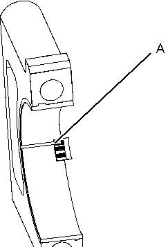

Illustration 1 g01152855
Typical Example
4. Remove all of Tooling (A) before you install the bearing cap.
Note: When Tooling (A) is used, the readings can sometimes be unclear. For example, all parts of Tooling (A) are not the same width. Measure the major width in order to ensure that the parts are within the specification range. Refer to Specifications Manual, "Connecting Rod Bearing Journal" and Specifications Manual, "Main Bearing Journal" for the correct clearances.
Product: WHEEL LOADER
Model: 966 GC WHEEL LOADER SGW
Configuration: 966GC Wheel Loader SGW00001-UP (MACHINE) POWERED BY C9.3 Engine
Disassembly and Assembly
C9.3B Engines for Caterpillar Built Machines
Media Number -M0096470-01 Publication Date -01/12/2019
SMCS - 1358-010
Removal Procedure
Date Updated -06/12/2019
i07104414
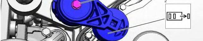

Reference: Special Instruction, "Visual Service Procedures - Colors and Symbols" , M0066576 Illustration 1
Installation Procedure
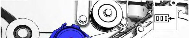
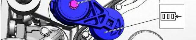

Copyright 1993 - 2025 Caterpillar Inc. All Rights Reserved. Private Network For SIS Licensees. Fri Feb 21 13:11:33 UTC+0700 2025
Product: WHEEL LOADER
Model: 966 GC WHEEL LOADER SGW
Configuration: 966GC Wheel Loader SGW00001-UP (MACHINE) POWERED BY C9.3 Engine
Disassembly and Assembly
C9.3B Engines for Caterpillar Built Machines
Media Number -M0096470-01 Publication Date -01/12/2019
Date Updated -06/12/2019
i07030947
Camshaft - Install
SMCS - 1210-012
Installation Procedure
Reference: Special Instruction, "Visual Service Procedures - Colors and Symbols" M0066576
Table 1
Required Tools
Tool Part Number Part Description Qty
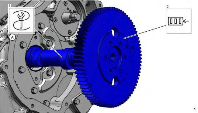
1 g06201944
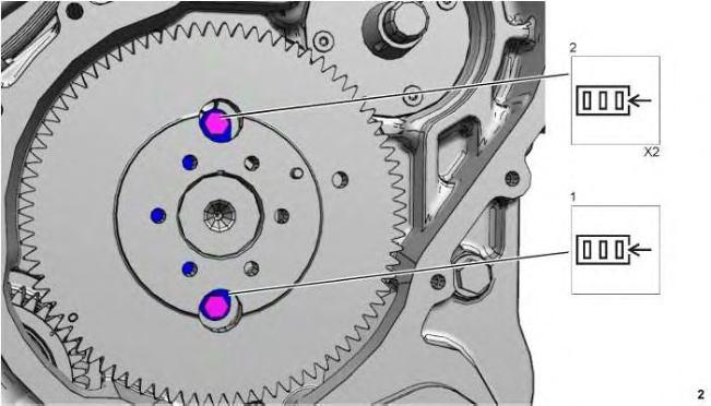
2 g06202880
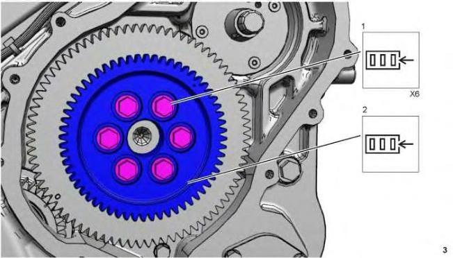
3 g06203020
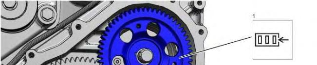


4 g06203261
a. Install the rocker arm and shaft.
b. Install the front cover.
c. Install the valve lifters. Copyright 1993 - 2025 Caterpillar Inc. All Rights Reserved. Private Network For SIS Licensees. Fri Feb 21 12:57:46 UTC+0700 2025
Product: WHEEL LOADER
Model: 966 GC WHEEL LOADER SGW
Configuration: 966GC Wheel Loader SGW00001-UP (MACHINE) POWERED BY C9.3 Engine
Disassembly and Assembly
C9.3B Engines for Caterpillar Built Machines
Media Number -M0096470-01
Publication Date -01/12/2019
Date Updated -06/12/2019
i07026677
Camshaft - Remove
SMCS - 1210-011
Removal Procedure
Reference: Special Instruction, "Visual Service Procedures - Colors and Symbols" M0066576
Table 1
Required Tools
Tool Part Number Part Description Qty A 8T-2998 Lubricant -
Start By:
a. Remove the rocker arm and shaft.
b. Remove the front cover.
c. Remove the valve lifters.
Set the number one piston to top center on the compression stroke. Refer to Testing and Adjusting, "Finding Top Center for No. 1 Piston."
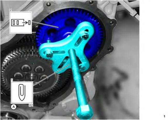
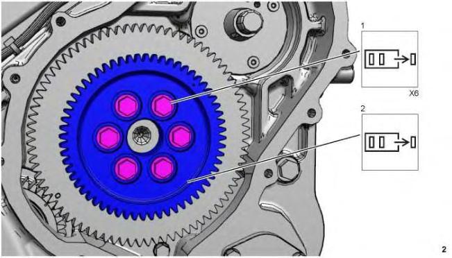
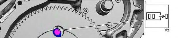
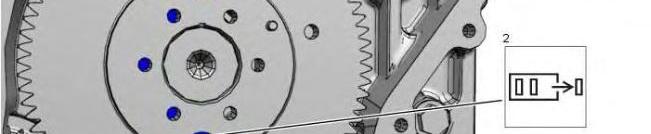

3 g06201863
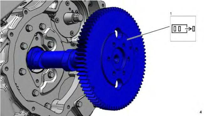
4 g06201906
NOTICE
Do not damage the lobes of the bearings when the camshaft is removed or installed.
Copyright 1993 - 2025 Caterpillar Inc.
This is the sample of the manual click on the download link for complete manual
For some reason if link does not work download this pdf and then click