
Note: Use Bookmarks panel to navigate
This is the sample of the manual click on the download link for complete manual
Note: Use Bookmarks panel to navigate
This is the sample of the manual click on the download link for complete manual
For some reason if link does not work download this pdf and then click

Product: WHEEL LOADER
Model: 962M WHEEL LOADER J2S
Configuration: 962M Wheel Loader J2S00001-UP (MACHINE) POWERED BY C7.1 Engine
Disassembly and Assembly
950M, 962M, 950M Z and 962M Z Wheel Loaders
Media Number -UENR3108-03
Publication Date -01/08/2014
SMCS - 1064-010
Removal Procedure
Date Updated -06/09/2016
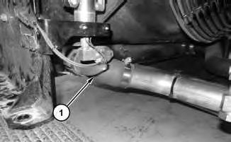
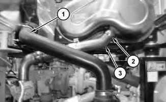
Illustration 2 g03565660
2. Remove bolts (2) and reposition radiator top tank bracket (3). Disconnect hose (4).
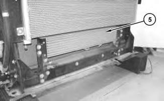
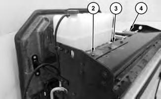
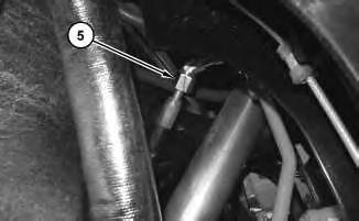
Illustration 3
3. Remove fuel cooler (5).
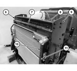
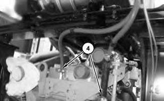
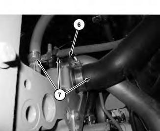
Illustration 4
g03565661
4. Remove bolts (6) and baffle (7). Remove bolts (9) and bracket (8). Disengage lever (11) and reposition bracket (10).
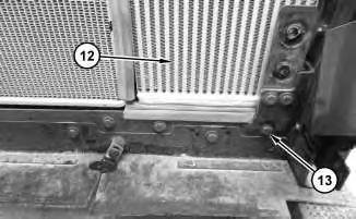
5. Remove bolts (13) and aftercooler core assembly (12).
1. Install aftercooler core assembly (12) in the reverse order of removal.
Copyright 1993 - 2024 Caterpillar Inc. All Rights Reserved. Private Network For SIS Licensees. Fri Apr 5 12:13:39 UTC+0530 2024
Product: WHEEL LOADER
Model: 962M WHEEL LOADER J2S
Configuration: 962M Wheel Loader J2S00001-UP (MACHINE) POWERED BY C7.1 Engine
Disassembly and Assembly
950M, 962M, 950M Z and 962M Z Wheel Loaders Media
SMCS - 1051-010
Removal Procedure
Hot engine components can cause injury from burns. Before performing maintenance on the engine, allow the engine and the components to cool.
1. Raise the engine hood.
2. Turn the battery disconnect to the off position.
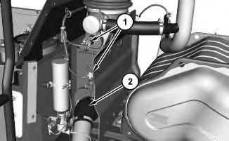
Illustration 1 g03696631
3. Disconnect hose (2) and harness assemblies (1).
2
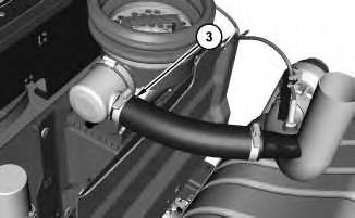
4. Disconnect hose (3).
3
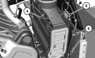
5. Remove cable strap (4) from the harness assembly . Disconnect module (5) and reposition out of the way. Remove cable straps (6) from the harness assembly.
4
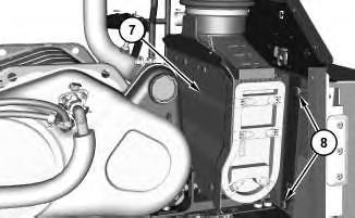
6. Remove bolts (8) from both sides. Remove air cleaner assembly (7).
Installation Procedure
1. Install air cleaner assembly (7) in the reverse order of removal.
Copyright 1993 - 2024 Caterpillar Inc. All Rights Reserved. Private Network For SIS Licensees. Fri Apr 5 12:15:49 UTC+0530 2024
Product: WHEEL LOADER
Model: 962M WHEEL LOADER J2S
Configuration: 962M Wheel Loader J2S00001-UP (MACHINE) POWERED BY C7.1 Engine
Disassembly and Assembly
950M, 962M, 950M Z and 962M Z Wheel Loaders
Media
SMCS - 1405-010
Removal Procedure
1. Raise the engine hood.
2. Turn the battery disconnect switch to the OFF position.
3. Open the panel on the left side of the engine.
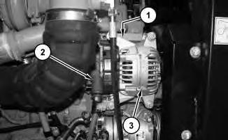
Illustration 1 g03694253 Typical example.
4. Remove the belt. Refer to Operation and Maintenance Manual, "Belts - Inspect / Adjust / Replace" to remove and install the belt.
5. Disconnect positive cable assembly (2).
6. Disconnect negative cable assembly (1) located behind alternator (3).
7. Remove alternator (3).
1. Install alternator (3) in the reverse order of removal.
Copyright 1993 - 2024 Caterpillar Inc. All Rights Reserved. Private Network For SIS Licensees. Fri Apr 5 12:05:24 UTC+0530 2024
Product: WHEEL LOADER
Model: 962M WHEEL LOADER J2S
Configuration: 962M Wheel Loader J2S00001-UP (MACHINE) POWERED BY C7.1 Engine
Disassembly and Assembly
950M, 962M, 950M Z and 962M Z Wheel Loaders
SMCS - 1358-010
Removal Procedure
1. Open the hood.
2. Turn the battery disconnect switch to the OFF position.
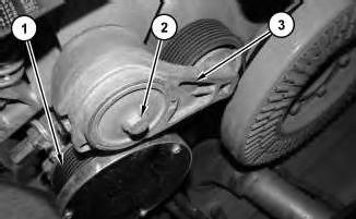
Illustration 1
g03694903
View between the cooling package and the front of the engine.
3. Remove belt (1). Refer to Operation and Maintenance Manual, "Belts - Inspect / Adjust / Replace" to remove and install the belt.
4. Remove bolt (2) and belt tensioner (3).
Installation Procedure
1. Install belt tensioner (3) in the reverse order of removal.
Product: WHEEL LOADER
Model: 962M WHEEL LOADER J2S
Configuration: 962M Wheel Loader J2S00001-UP (MACHINE) POWERED BY C7.1 Engine
Disassembly and Assembly
950M, 962M, 950M Z and 962M Z Wheel Loaders
Clean Emissions Module - Remove and Install
SMCS - 1050; 7279
Removal Procedure
Hot engine components can cause injury from burns. Before performing maintenance on the engine, allow the engine and the components to cool.
At operating temperature, the engine coolant is hot and under pressure.
Steam can cause personal injury.
Check the coolant level only after the engine has been stopped and the fill cap is cool enough to touch with your bare hand.
Remove the fill cap slowly to relieve pressure.
Cooling system conditioner contains alkali. Avoid contact with the skin and eyes to prevent personal injury.
1. Raise the hood.
2. Turn the battery disconnect switch to the OFF position.
3. Drain the coolant below the level of the head. Refer to Operation and Maintenance Manual, "Cooling System Coolant (ELC) - Change" for the correct draining and filling procedures.
1
4. Disconnect tube (1) from the air filter box. Loosen clamp (2) and disconnect tube (3). Discard clamp (2).
2
5. Disconnect hoses (4).
3
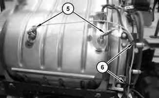
6. Disconnect harness assemblies (5). Remove cable straps (6).
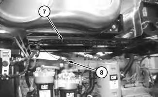
Illustration 4
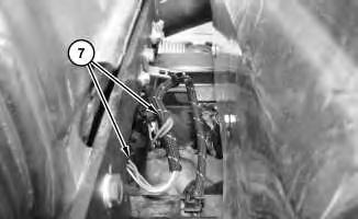
Illustration 5
7. Remove all cable straps along harness assembly (7). Disconnect ether hose (8). Disconnect harness assembly (7).
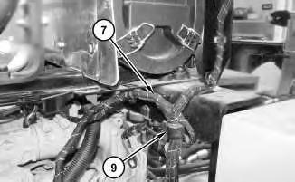
Illustration 6
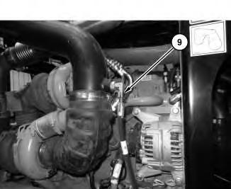
8. Remove all cable straps on harness assembly (7). Remove clip (9).
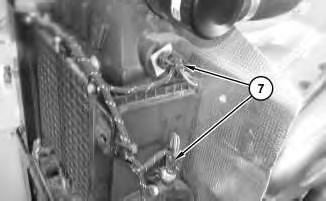
7
9. Disconnect harness assembly (7) from the air filter box. Remove all remaining cable straps on harness assembly (7).
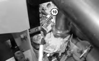
8
10. Remove heat shield (10).
9
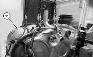
11. Attach a suitable lifting device to clean emissions module (11). The weight of clean emissions module (11) is approximately 172 kg (380 lb).
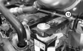
Illustration 10
g03693970
12. Remove bolt (12). Repeat for the opposite side.
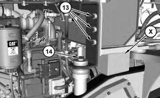
Illustration 11
g03694041
View of right side of the hydraulic tank. Platform removed for photographic purposes.
13. Place suitable cribbing (X) between the hydraulic tank and the frame in order to support the hydraulic tank when the clean emissions module is removed. Remove bolts (13) from both sides of the hydraulic tank. Remove bolts (14) from both sides.
14. Remove clean emissions module (11).
1. Install clean emissions module (11) in the reverse order of removal.
a. Tighten harness assemblies (5) to a torque of 1.2 ± 0.20 N·m (11 ± 2 lb in).
b. Replace clamp (2) with a new clamp. Tighten clamp (2) to the following torque 35 ± 2 N·m (26 ± 1 lb ft).
Copyright 1993 - 2024 Caterpillar Inc. All Rights Reserved.
Network For SIS Licensees. Fri Apr 5 12:08:45 UTC+0530 2024
Product: WHEEL LOADER
Model: 962M WHEEL LOADER J2S
Configuration: 962M Wheel Loader J2S00001-UP (MACHINE) POWERED BY C7.1 Engine
Disassembly and Assembly
950M, 962M, 950M Z and 962M Z Wheel Loaders
Cooler) - Remove and Install
SMCS - 1063-010; 1353-010; 1356-010; 1374-010
Removal Procedure
Table 1
Required Tools
Tool Part Number Part Description Qty
A FT-2674 Vacuum Cap 1
Start By:
a. Remove hood.
Personal injury can result from hydraulic oil pressure and hot oil.
Hydraulic oil pressure can remain in the hydraulic system after the engine has been stopped. Serious injury can be caused if this pressure is not released before any service is done on the hydraulic system.
Make sure all of the work tools have been lowered to the ground, and the oil is cool before removing any components or lines. Remove the oil filler cap only when the engine is stopped, and the filler cap is cool enough to touch with your bare hand.
At operating temperature, the engine coolant is hot and under pressure.
Steam can cause personal injury.
Check the coolant level only after the engine has been stopped and the fill cap is cool enough to touch with your bare hand.
Remove the fill cap slowly to relieve pressure.
Cooling system conditioner contains alkali. Avoid contact with the skin and eyes to prevent personal injury.
Personal injury can result from contact with refrigerant.
Contact with refrigerant can cause frost bite. Keep face and hands away to help prevent injury.
Protective goggles must always be worn when refrigerant lines are opened, even if the gauges indicate the system is empty of refrigerant.
Always use precaution when a fitting is removed. Slowly loosen the fitting. If the system is still under pressure, release it slowly in a well ventilated area.
Personal injury or death can result from inhaling refrigerant through a lit cigarette.
Inhaling air conditioner refrigerant gas through a lit cigarette or other smoking method or inhaling fumes released from a flame contacting air conditioner refrigerant gas, can cause bodily harm or death.
Do not smoke when servicing air conditioners or wherever refrigerant gas may be present.
Use a certified recovery and recycling cart to properly remove the refrigerant from the air conditioning system.
1. Refer to Operation and Maintenance Manual, "Cooling System Coolant (ELC) - Change" for the correct draining and filling procedures.
2. Recover the air conditioner refrigerant from the air conditioner system. Refer to Service Manual, SENR5664, "Air Conditioning and Heating Systems with R-134a Refrigerant for
All Caterpillar Machines " for the procedure. Refer to Special Publication, NENG2500, "Air Conditioning Tools" for the correct tools.
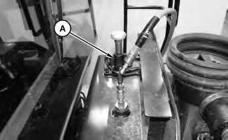
1
3. Remove the hydraulic tank breather assembly and install Tooling (A). Attach an air supply hose onto Tooling (A). Apply 276 kPa (40 psi) to 414 kPa (60 psi) of air. This procedure will pull vacuum on the hydraulic system.
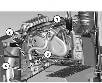
Illustration 2
g03614718
4. Disconnect hose assembly (1). Remove cable straps (2). Disconnect harness assembly (3) and remove sensor assembly (4).
3
5. Disconnect hose assembly (5).
4
6. Disconnect tube assembly (6) and hoses (7).
5
7. Disconnect hoses (8).
6
8. Disconnect hose assembly (9).
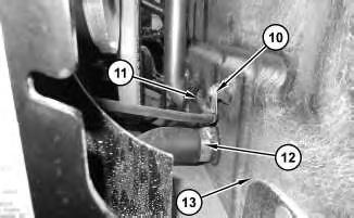
7
9. Remove clip (10) and pull hose (11) through engine shield (13). Disconnect hose (12).
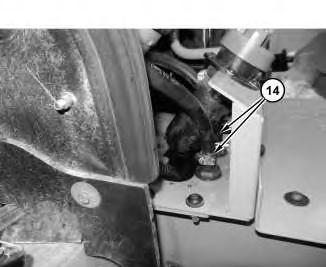
Illustration 8
10. Disconnect hoses (14).
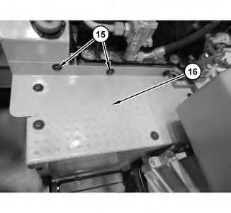
Illustration 9
11. Remove bolts (15) and cover (16).
10
11
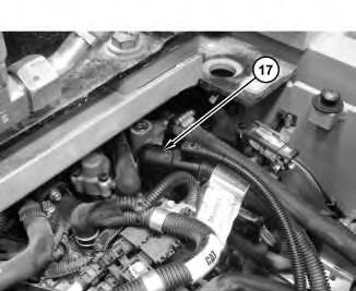
12
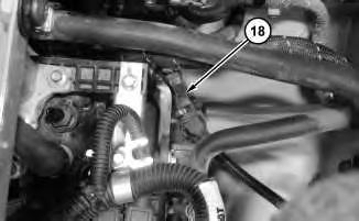
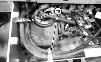
12. Disconnect hose assembly (17) and harness assembly (18). Remove clips (19).
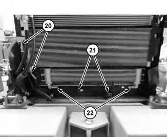
Illustration 13
g03615482
13. Disconnect hose assemblies (20) and (22). Remove clips (21).
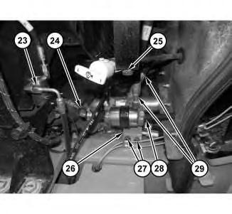
Illustration 14
g03615520
14. Disconnect hose assemblies (23) and (29). Disconnect hoses (24) and (28). Remove clip (25). Remove bolts (27) and reposition bracket (26).
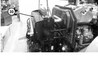
Illustration 15 g03615657
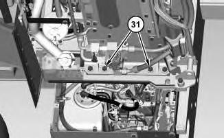
Illustration 16 g03615716
15. Attach a suitable lifting device to cooling system package (30). Remove bolts (31) and cooling system package (30). The weight of cooling system package (30) is approximately 362 kg (800 lb).
1. Install cooling system package (30) in the reverse order of removal.
Copyright 1993 - 2024 Caterpillar Inc. All Rights Reserved. Private Network For SIS Licensees. Fri Apr 5 12:12:33 UTC+0530 2024
This is the sample of the manual click on the download link for complete manual
For some reason if link does not work download this pdf and then click