DOWNLOAD LINK
For some reason if link does not work download this pdf and then click
2
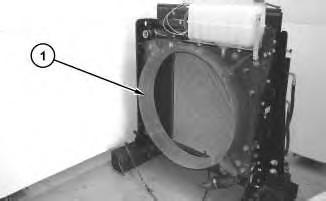
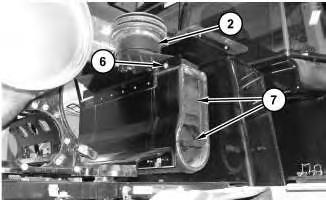
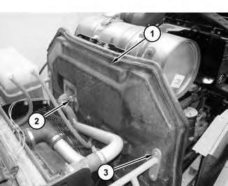
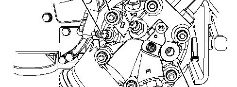
2. Remove baffles (2) .
3
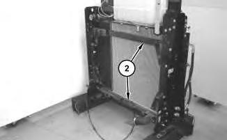
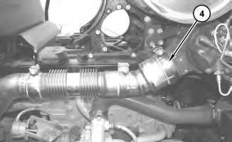
3. Remove angle (3). Remove exhaust monitor (4) .
Illustration
g02716020
Illustration
g02716022
Illustration 4
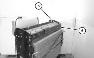
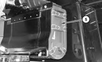
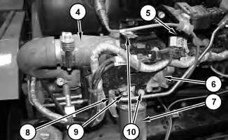
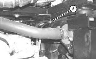
4. Remove bracket (5). Remove plate (6) .
Illustration 5
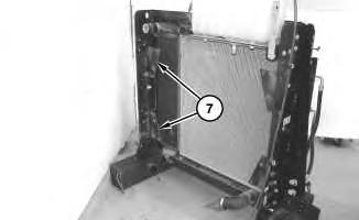
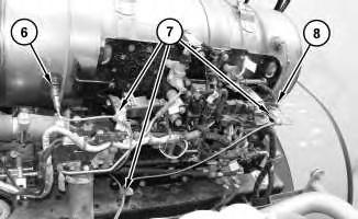
5. Remove brackets(7) .
Illustration 6
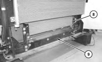
6. Remove fuel cooler (8). Remove baffle (9) .
g02716199
g02716205
7
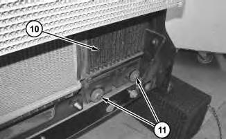
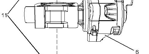
7. Remove bolts (11) from aftercooler core assembly (10) .
8
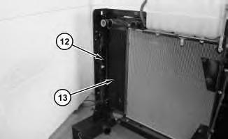
8. Open access cover (12) and remove aftercooler core assembly (10) .
Installation Procedure
1. Install aftercooler core assembly (10) in the reverse order of removal.
Copyright 1993 - 2020 Caterpillar Inc. All Rights Reserved. Private Network For SIS Licensees.
Illustration
g02716216
Illustration
g02716220
Product: WHEEL LOADER
Model: 962K WHEEL LOADER X4T
Configuration: 962K Wheel Loader X4T00001-UP (MACHINE) POWERED BY C7.1 Engine
Disassembly and Assembly
950K and 962K Wheel Loaders C7.1 Engine Supplement
Media Number -KENR5788-00
Publication Date -01/09/2011
Air Cleaner - Remove and Install
SMCS - 1051-010
Removal Procedure
1. Raise the engine hood.
2. Turn the battery disconnect to the off position.
Illustration 1
Date Updated -28/09/2011
i04429030
g02623059
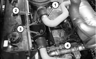
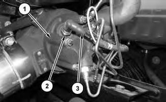
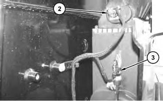
3. Disconnect hose (1), harnessassemblies(3), and tube assembly (4) from air cleaner assembly (2) .
2
4. Remove cover (5) .
3
5. Remove filter assemblies (7). Remove bolts (6) and air cleaner assembly (2) .
Installation Procedure
1. Install air cleaner assembly (2) in the reverse order of removal. Copyright 1993 - 2020 Caterpillar Inc.
Illustration
g02623116
Illustration
g02623651
Product: WHEEL LOADER
Model: 962K WHEEL LOADER X4T
Configuration: 962K Wheel Loader X4T00001-UP (MACHINE) POWERED BY C7.1 Engine
Disassembly and Assembly
950K and 962K Wheel Loaders C7.1 Engine Supplement
Media Number -KENR5788-00
Publication Date -01/09/2011
Date Updated -28/09/2011
Air Control Valve - Remove and Install - Clean Emissions Module
SMCS - 108A-010
Removal Procedure
Hot engine components can cause injury from burns. Before performing maintenance on the engine, allowthe engine and the components to cool.
1. Open the hood.
i04437049
Illustration 1
2. Remove bolt (2) from the soot antenna wire clamps. Remove bolts (3) and remove shield (1) .
2
g02626186
Illustration
g02626341
Illustration 3 g02626401
3. Remove hose assemblies(4) and (7) .
4. Disconnect harnessassembly (5) .
5. Disconnect tube assembly (8) .
6. Remove bolts (10) and the reposition bracket.
7. Remove bolts (9) .
8. Remove air control valve (6) .
9. Remove O-ring seals (11) from air control valve (6) .
Installation Procedure
1. Install air control valve (6) in the reverse order of removal.
a. Tighten bolts (9) to a torque 28 N·m (248 lb in). Tue Nov 3 22:41:44 UTC+0530 2020
Product: WHEEL LOADER
Model: 962K WHEEL LOADER X4T
Configuration: 962K Wheel Loader X4T00001-UP (MACHINE) POWERED BY C7.1 Engine
Disassembly and Assembly
950K and 962K Wheel Loaders C7.1 Engine Supplement
Media Number -KENR5788-00
Publication Date -01/09/2011
Alternator - Remove and Install
SMCS - 1405-010
Removal Procedure
1. Raise the engine hood.
2. Turn the battery disconnect switch to the OFFposition.
3. Open the panel on the left side of the engine.
Illustration 1 g02605038
Date Updated -28/09/2011
i04408065
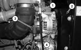
4. Remove shield assembly (2). Remove the serpentine belt. Refer to Operation and Maintenance Manual, "Belts - Inspect / Adjust / Replace".
5. Disconnect positive cable assembly (3) .
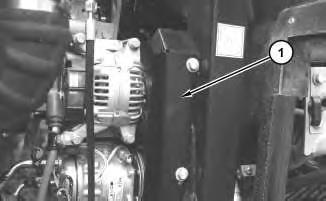
6. Disconnect negative cable assembly (1) located behind alternator (4) .
7. Remove alternator (4) .
Installation Procedure
1. Install alternator (4) in the reverse order of removal. Copyright 1993 - 2020 Caterpillar Inc. All Rights Reserved. Private Network For SIS Licensees.
Product: WHEEL LOADER
Model: 962K WHEEL LOADER X4T
Configuration: 962K Wheel Loader X4T00001-UP (MACHINE) POWERED BY C7.1 Engine
Disassembly and Assembly
950K and 962K Wheel Loaders C7.1 Engine Supplement
Media Number -KENR5788-00
Publication Date -01/09/2011 Date Updated -28/09/2011
ARD Spark Plug - Remove and Install
SMCS - 1555-010
Removal Procedure
Table 1
Required Tools
A - 22mm Spark Plug Socket 1
The ignition system may cause an electrical shockhazard, which may cause personal injury or death. Avoid contacting the ignition system components and the ignition system wiring during operation.
Hot engine components can cause injury from burns. Before performing maintenance on the engine, allowthe engine and the components to cool.
i04437069
1. Raise the hood.
2. Turn the battery disconnect switch to the OFFposition.
Illustration 1 g02626999
3. Disconnect ignition wire (3) from spark plug (2) .
4. Use Tooling (A) in order to remove spark plug (2) from ARD combustion head (1) .
Installation Procedure
1. Install ARD spark plug (2) in the reverse order of removal.
a. Use Tooling (A) in order to install spark plug (2). Torque spark plug (2) to a torque of 47 N·m (35 lb ft).
Product: WHEEL LOADER
Model: 962K WHEEL LOADER X4T
Configuration: 962K Wheel Loader X4T00001-UP (MACHINE) POWERED BY C7.1 Engine
Disassembly and Assembly
950K and 962K Wheel Loaders C7.1 Engine Supplement
Media Number -KENR5788-00
Publication Date -01/09/2011
Belt Tensioner - Remove and Install
SMCS - 1358-010
Removal Procedure
1. Open the hood.
2. Turn the battery disconnect switch to the OFFposition.
Illustration 1 g02620740
3. Remove cover (1) .
Date Updated -28/09/2011
i04419690
2
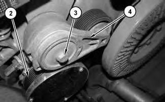
4. Remove belt (2). Refer to Operation and Maintenance Manual, "Belts - Inspect / Adjust / Replace".
5. Remove bolt (3) and belt tensioner (4) .
Installation Procedure
1. Install belt tensioner (4) in the reverse order of removal.
1993 - 2020 Caterpillar Inc. All Rights Reserved.
Network For SIS Licensees.
Product: WHEEL LOADER
Model: 962K WHEEL LOADER X4T
Configuration: 962K Wheel Loader X4T00001-UP (MACHINE) POWERED BY C7.1 Engine
Disassembly and Assembly
950K and 962K Wheel Loaders C7.1 Engine Supplement
Media Number -KENR5788-00
Publication Date -01/09/2011
Date Updated -28/09/2011
i04511070
Clean Emissions Module - Remove and Install
SMCS - 1050; 7279
Removal Procedure
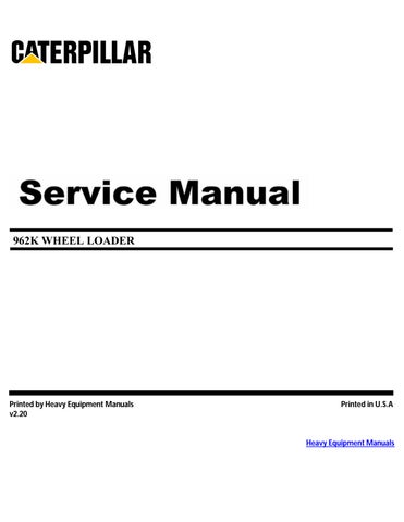
Illustration 1
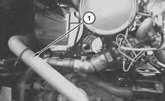
1. Remove tube assembly (1) .
2
2. Disconnect harnessassemblies(2) and (3) .
3
Note: The ball clamp orientation must be marked prior to removal for installation purposes.
3. Remove ball clamp (4) and discard.
Illustration
g02688917
Illustration
g02688939
4
4. Remove clip (5) .
5
5. Remove soot sensors (6) and (8). Remove clips (7) .
Illustration
g02689397
Illustration
g02689440
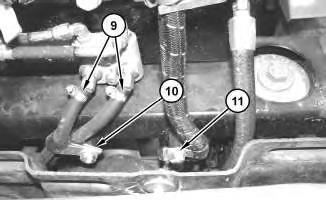
Illustration 6
g02690597
6. Disconnect hoses (9). Remove clips (10) and clip (11) .
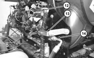
Illustration 7
7. Disconnect harnessassembly (12). Remove bracket (13). Remove hose assembly (14) .
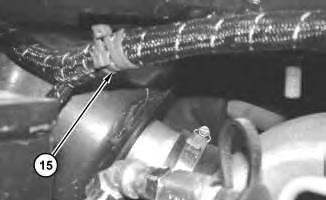
Illustration 8
8. Remove cable strap (15) .
g02690656
g02690671
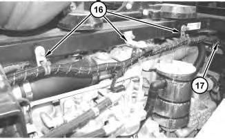
9
9. Remove clips (16). Remove clip (17).
Illustration 10
Illustration 11
Illustration
g02691217
g02692396
g02695957
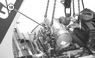
10. Attach a suitable lifting device to clean emissions module (18). The weight of the clean emissions module (18) isapproximately 254 kg (560 lb).
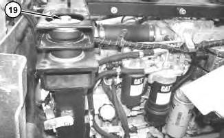
11. Remove bolts (19) and remove clean emissions module (19) .
Installation Procedure
1. Install clean emissions module (18) in the reverse order of the removal.
a. Tighten ball clamp (4) to a torque of 35 ± 2 N·m (26 ± 2 lb ft).
1993 - 2020 Caterpillar Inc.
Product: WHEEL LOADER
Model: 962K WHEEL LOADER X4T
Configuration: 962K Wheel Loader X4T00001-UP (MACHINE) POWERED BY C7.1 Engine
Disassembly and Assembly
950K and 962K Wheel Loaders C7.1 Engine Supplement
Media Number -KENR5788-00
Publication Date -01/09/2011 Date Updated -28/09/2011
i04429029
Combustion Head - Remove and Install - Clean Emissions Module
SMCS - 108B-010
Removal Procedure
Table 1
Required Tools
Fuel leaked or spilled onto hot surfaces or electrical components can cause a fire. To help prevent possible injury, turn the start switch off when changing fuel filtersor water separator elements. Clean up fuel spills immediately.
NOTICE
Keep all parts clean from contaminants.
Contaminants may cause rapid wear andshortened component life.
Hot engine components can cause injury from burns. Before performing maintenance on the engine, allowthe engine and the components to cool.
1. Open the hood.
2. Drain the coolant until the level is below the combustion head. Refer to Operation and Maintenance Manual, "Cooling System Coolant - Change" for the correct draining and filling procedures.
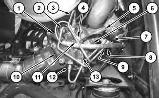
1
3. Remove bolts (8) (not shown) from tube assembly clamps (9) .
4. Disconnect fuel tube assembly (10) from combustion head (12). Plug the tube assembly with new plugs. Cap all open connectors on the combustion head with new caps.
5. Disconnect coolant tube assembly (2) and coolant tube assembly (3) from combustion head (10). Plug the tube assemblies with new plugs. Cap all open connectors on the combustion head with newcaps.
6. Remove bolt (4) from the ground strap and disconnect ignition wire (1) from the spark plug.
7. Remove allen head screw(11) and remove the clamp from combustion head (10). Remove heated nozzle connection (7) from the combustion head.
8. Remove flame detection temperature sensor (13) from combustion head (10). Refer to Disassembly and Assembly, "Flame Detection Temperature Sensor - Remove and Install"for the correct procedure.
9. Remove hex head bolts (5) and remove gasket (6) (not shown).
Illustration
g02623338
Illustration 2 g02624224
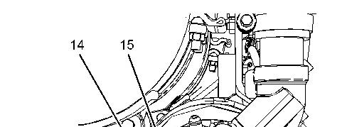
10. Remove spark plug (14) from combustion head (10). Refer to Disassembly and Assembly, "Spark Plug - Remove and Install" for the correct procedure.
11. Loosen nuts (15) in a crisscross pattern. Remove nuts(15) from combustion head (9) .
This is the sample of the manual click on the download link for complete manual