Product: WHEEL LOADER
Model: 962G WHEEL LOADER 4PW
Configuration: 962G Wheel Loader 4PW00001-UP (MACHINE) POWERED BY 3126 Engine
Operation and Maintenance Manual
Work Tool (Custom) and 343-8734 Fusion Pallet Fork
Media Number -GEBU0004-00 Publication Date -01/04/2009 Date Updated -23/04/2009
Foreword
SMCS - 7000
Literature Information
This manual should be stored in the operator's compartment in the literature holder or seat back literature storage area.
This manual contains safety information, operation instructions, transportation information, lubrication information and maintenance information.
Some photographs or illustrations in this publication show details that can be different from your work tool. Guards and covers might have been removed for illustrative purposes.
Continuing improvement and advancement of product design might have caused changes to your work tool which are not included in this publication. Read, study and keep this manual with the machine that your work tool is installed on.
Whenever a question arises regarding your work tool, or this publication, please consult your Caterpillar dealer for the latest available information.
Safety
The safety section lists basic safety precautions. In addition, this section identifies the text and locations of safety signs and labels used on the work tool.
Read and understand the basic precautions listed in the safety section before operating or performing lubrication, maintenance and repair on this work tool.
Operation
The operation section is a reference for the new operator and a refresher for the experienced operator. This section includes a discussion of gauges, switches, machine controls, work tool controls, transportation and towing information.
s00272057
Photographs and illustrations guide the operator through correct procedures of checking, starting, operating and stopping the work tool.
Operating techniques outlined in this publication are basic. Skill and techniques develop as the operator gains knowledge of the work tool and its capabilities.
Maintenance
The maintenance section is a guide to equipment care. The illustrated, step-by-step instructions are grouped by service intervals. Items without specific intervals are listed under the when required interval. Items in the maintenance intervals schedule are referenced to detailed instructions that follow.
Maintenance Intervals
Calendar intervals shown (daily, weekly, monthly, etc) can be used instead of service hour meter intervals if they provide more convenient servicing schedules and approximate the indicated service hour meter reading. Recommended service should always be performed at the interval that occurs first.
Under extremely severe, dusty or wet operating conditions, more frequent lubrication than is specified in the maintenance intervals schedule might be necessary.
Perform service on items at multiples of the original requirement. For example, at every 500 service hours or 3 months, also service those items listed under every 250 service hours or monthly and every 10 service hours or daily.
Copyright 1993 - 2025 Caterpillar Inc. All Rights Reserved. Private Network For SIS Licensees.
Wed Jan 8 22:28:47 UTC+0530 2025
DOWNLOAD LINK
For some reason if link does not work download this pdf and then click
Product: WHEEL LOADER
Model: 962G WHEEL LOADER 4PW
Configuration: 962G Wheel Loader 4PW00001-UP (MACHINE) POWERED BY 3126 Engine
Operation and Maintenance Manual
Work Tool (Custom) and 343-8734 Fusion Pallet Fork
Media Number -GEBU0004-00
Publication Date -01/04/2009
Hydraulic Fittings - Inspect
SMCS - 5057-040-X6
Date Updated -23/04/2009
i01203214
Check all hydraulic fittings for damaged fittings or leaks. Replace all damaged parts or missing parts. Wipe all fittings before you connect the hydraulic lines.
Copyright 1993 - 2025 Caterpillar Inc. All Rights Reserved. Private Network For SIS Licensees.
Wed Jan 8 22:35:23 UTC+0530 2025
Product: WHEEL LOADER
Model: 962G WHEEL LOADER 4PW
Configuration: 962G Wheel Loader 4PW00001-UP (MACHINE) POWERED BY 3126 Engine
Operation and Maintenance Manual
Work Tool (Custom) and 343-8734 Fusion Pallet Fork
Media Number -GEBU0004-00
Publication Date -01/04/2009
Maintenance Interval Schedule
SMCS - 6700
Date Updated -23/04/2009
Ensure that all safety information, warnings, and instructions are read and understood before any operation or any maintenance procedures are performed.
The user is responsible for the performance of maintenance, including all adjustments, the use of proper lubricants, fluids, filters, and the replacement of components due to normal wear and aging. Failure to adhere to proper maintenance intervals and procedures may result in diminished performance of the product and/or accelerated wear of components.
Use mileage, fuel consumption, service hours, or calendar time, WHICH EVER OCCURS FIRST, in order to determine the maintenance intervals. Products that operate in severe operating conditions may require more frequent maintenance.
Note: Before each consecutive interval is performed, all maintenance from the previous interval must be performed.
When Required
Pallet Fork - Inspect
Pallet Fork - Lubricate
Every 10 Service Hours or Daily
Hydraulic Fittings - Inspect
Copyright 1993 - 2025 Caterpillar Inc. All Rights Reserved.
Private Network For SIS Licensees.
Wed Jan 8 22:35:11 UTC+0530 2025
i03549482
Product: WHEEL LOADER
Model: 962G WHEEL LOADER 4PW
Configuration: 962G Wheel Loader 4PW00001-UP (MACHINE) POWERED BY 3126 Engine
Operation and Maintenance Manual
Work Tool (Custom) and 343-8734 Fusion Pallet Fork
Media Number -GEBU0004-00 Publication Date -01/04/2009
Pallet Fork - Inspect
SMCS - 6136-040
Descriptions of the Fork Tine
Parts
Date Updated -23/04/2009
i04004068
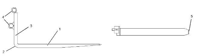
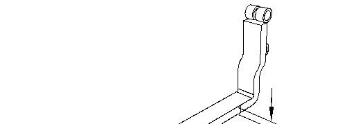
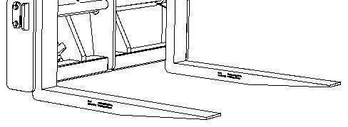
Illustration 1 g01598401
(1) Blade - The horizontal part of the fork tine that supports the load
(2) Heel - The radius on the fork tine that connects the blade to the shank
(3) Shank - The vertical part of the fork tine that has the hooks that support the fork tines attached.
(4) Hook or Hanger - Carriers that mount the fork tines to the carriage
(5) Tip - The free end of the blade
Surfaces
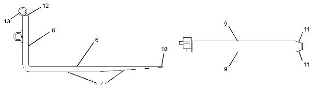
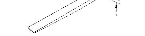
Illustration 2
(6) Upper Face of the Blade - The upper surface of the blade that carries the load
(7) Bottom of Heel - The lower surface of the blade that includes the tapers
(8) Front Face of Shank - The distance for the load center is measured from the front face of the shank and the face of the shank contacts the load.
(9) Flanks - The side faces of the blade and the shank.
(10) Blade Bevel - The upper and lower surfaces of the tip on the blade that are tapered for easy insertion of the fork tines
(11) Tip Flanks - The side surfaces of the tip on the blade that are tapered for easy insertion of the fork tines
(12) Top of Shank - The upper surface on the shank
(13) Shaft - The tubes that are mounted on the fork tines for mounting the fork tines to the carriage
Dimensions
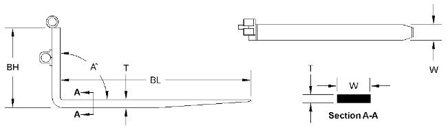
Illustration 3
(T) Thickness - The thickness of the blade at the closest point to the heel
(W) Width - The width of the blade at the closest point to the heel
(BH) Back Height - The distance from the bottom of the blade to the top of the shank
(BL) Length - The length of the blade is measured from the front face on the shank to the tip on the blade.
(A) Angle - The angle from the upper surface of the blade to the front face of the shank.
Inspection of the Fork Tines
Check the fork tines daily for any twisting or bending of the fork tines. If any twisting or bending is observed, the fork tines should be changed prior to any lifting operation. If the fork tines are damaged, consult your Cat dealer.
Check the fork tines for wear or for damage. Inspect the welds, the locks, the shafts, and the fork tines for damage. If the components are damaged, consult your Cat dealer. Refer to , "Daily Inspection" for additional information.
Blade Thickness
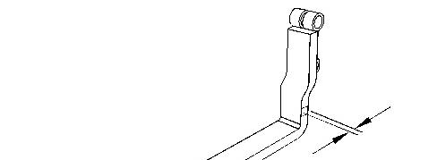
Illustration 4
g01600073
1. Measure the thickness of the shank. Ensure that the measuring device is held square across the shank in order to acquire an accurate measurement.
2. Measure the blade of the fork tine near the heel. Ensure that the measuring device is held square across the blade in order to acquire an accurate measurement.
3. Compare the measurement of the blade and the measurement of the shank.
4. If the difference in measurements is less than 10%, the fork tine can remain in service.
5. If the difference in measurements is greater than 10%, the fork tine must be taken out of service. Fork tine wear that is greater than 10%, represents a 20% reduction in the capacity of the fork tine.
Consult your Cat dealer for additional information.
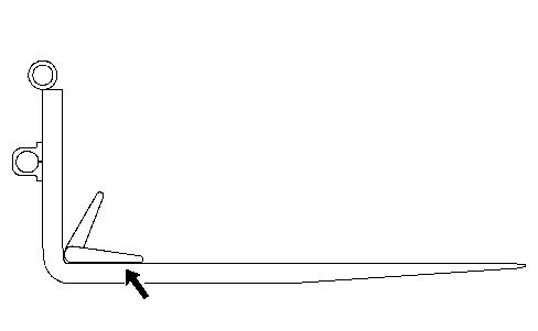
Angle of the Heel
Illustration 6 g01600075
1. Place a measuring device in the top inside area of the heel on top of the blade. Ensure that the measuring device is held flat against the blade in order to acquire an accurate measurement.
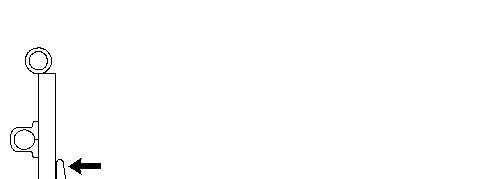
Illustration 7 g01600076
2. Move the upper arm of the measuring device toward the face of the shank. Ensure that the measuring device is held flat against the face of the shank in order to acquire an accurate measurement.
3. Check the angle that was measured with the device for the angle of the heel.
4. If the angle is between 87 degrees and 93 degrees, the fork tine can remain in service.
5. If the angle is less than 87 degrees or greater than 93 degrees, the fork tine must be taken out of service. The fork tines must be inspected for the following conditions: permanent deformation stress cracks other defects
Consult your Cat dealer for additional information.
Product: WHEEL LOADER
Model: 962G WHEEL LOADER 4PW
Configuration: 962G Wheel Loader 4PW00001-UP (MACHINE) POWERED BY 3126 Engine
Operation and Maintenance Manual
Work Tool (Custom) and 343-8734 Fusion Pallet Fork
Media Number -GEBU0004-00
Publication Date -01/04/2009
Pallet Fork - Lubricate
SMCS - 6136-086
Date Updated -23/04/2009
i03583260
Illustration 1 g01911637
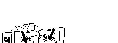
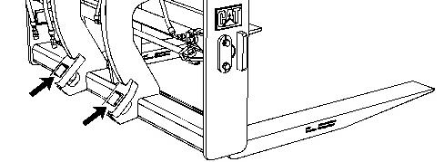
1. Coat the shafts with grease.
Illustration 2 g01911674
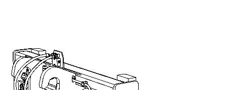
2. Coat the mounting holes for the quick coupler with grease.
ReferenceRefer to Operation and Maintenance Manual, SEBU6250, "Caterpillar Machine Lubricant Recommendations" for information on lubricants.
Copyright 1993 - 2025 Caterpillar Inc. All Rights Reserved. Private Network For SIS Licensees.
Wed Jan 8 22:35:51 UTC+0530 2025
Product: WHEEL LOADER
Model: 962G WHEEL LOADER 4PW
Configuration: 962G Wheel Loader 4PW00001-UP (MACHINE) POWERED BY 3126 Engine
Operation and Maintenance Manual
Work Tool (Custom) and 343-8734 Fusion Pallet Fork
Media Number -GEBU0004-00 Publication Date -01/04/2009 Date Updated -23/04/2009
Welding on Machines and Engines with Electronic Controls
SMCS - 1000; 7000
Proper welding procedures are necessary in order to avoid damage to the electronic controls and to the bearings. The following steps should be followed in order to weld on a machine or an engine with electronic controls.
Note: If you are welding on a work tool, remove the work tool from the host machine before welding.
1. Turn off the engine.
2. Turn the battery disconnect switch to the OFF position. If there is no battery disconnect switch, remove the negative battery cable at the battery.
3. Clamp the ground cable from the welder to the component that will be welded. Place the clamp as close as possible to the weld. Make sure that the electrical path from the ground cable to the component does not go through any bearing. Use this procedure in order to reduce the possibility of damage to the following components:
Bearings of the drive train
Hydraulic components
Electrical components
Other components of the machine
NOTICE
Do NOT use electrical components (ECM or sensors) or electronic component grounding points for grounding the welder.
i01828834
4. Protect any wiring harnesses from the debris which is created from welding. Protect any wiring harnesses from the splatter which is created from welding.
5. Use standard welding procedures in order to weld the materials together.
Copyright 1993 - 2025 Caterpillar Inc. All Rights Reserved. Private Network For SIS Licensees.
Wed Jan 8 22:34:57 UTC+0530 2025
Product: WHEEL LOADER
Model: 962G WHEEL LOADER 4PW
Configuration: 962G Wheel Loader 4PW00001-UP (MACHINE) POWERED BY 3126 Engine
Operation and Maintenance Manual
Work Tool (Custom) and 343-8734 Fusion Pallet Fork
Media Number -GEBU0004-00
Daily Inspection
SMCS - 6700
Publication Date -01/04/2009
Date Updated -23/04/2009
Personal injury or death can result from improperly checking for a leak.
Always use a board or cardboard when checking for a leak. Escaping air or fluid under pressure, even a pin-hole size leak, can penetrate body tissue causing serious injury, and possible death.
If fluid is injected into your skin, it must be treated immediately by a doctor familiar with this type of injury.
NOTICE
Accumulated grease and oil on a work tool is a fire hazard.
Remove debris with steam cleaning or high pressure water at any time a significant quantity of oil is spilled on the work tool.
Note: The work tool should be removed from the quick coupler during the daily inspection of the work tool. Uncoupling the work tool daily helps to prevent the coupler wedges from sticking.
For the maximum service life of the work tool, make a thorough walk-around inspection before you mount the machine and before you start the engine.
i03078661
Position the work tool on a level surface. Uncouple the work tool from the quick coupler. Refer to Operation and Maintenance Manual, "Operation - Uncoupling the Work Tool".
Lower the quick coupler to the ground in front of the machine. Stop the engine on the host machine. Remove the engine start switch key before exiting the machine. Refer to the Operation and Maintenance Manual of the host machine for additional information.
Clean any debris from the forks.
Clean any debris from the carriage assembly.
Inspect the work tool for the following conditions: loose bolts, broken parts, missing parts and worn parts.
Check the carriage assembly and the fork tines for wear or for damage. Inspect the welds, the locks, the shafts, and the fork tines for damage. If the components are damaged, consult your Caterpillar dealer.
Check the fork tines daily for any twisting or bending of the fork tines. If any twisting or bending is observed, the fork tines should be changed prior to any lifting operation. If the fork tines are damaged, consult your Caterpillar dealer.
If the pallet forks are not operated for long periods, the pallet forks must be lubricated. Refer to Operation and Maintenance Manual, "Pallet Fork - Lubricate" for information on lubricating the pallet forks.
Perform all repairs before the work tool is put into service.
Check the safety messages. Replace the safety messages when the safety messages are damaged. Replace the safety messages when you cannot read the safety messages. Replace the safety messages when the safety messages are missing.
Couple the work tool to the quick coupler. Refer to Operation and Maintenance Manual, "Operation - Coupling the Work Tool". After the work tool is coupled, ensure that the coupler wedges are fully engaged into the work tool.
1993 - 2025 Caterpillar Inc.
Product: WHEEL LOADER
Model: 962G WHEEL LOADER 4PW
Configuration: 962G Wheel Loader 4PW00001-UP (MACHINE) POWERED BY 3126 Engine
Operation and Maintenance Manual
Work Tool (Custom) and 343-8734 Fusion Pallet Fork
Media Number -GEBU0004-00
Publication Date -01/04/2009
Lifting and Tying Down
SMCS - 7500
Date Updated -23/04/2009
Improper lifting or tying down can allow the load to shift causing injury or death.
Note: Before you lift the fork, refer to the Operation and Maintenance Manual, "Specifications" for the weight of your fork.
Lifting the Fork
i03549481
Illustration 1 g01909253
Note: For lifting objects, use properly rated cables and properly rated slings. Position the lifting device in order to keep the fork level.
1. Use two lifting straps that are equal in length.
2. Place one lifting strap around the tube of the carriage near one end.
3. Place the other lifting strap around the tube of the carriage near the other end.
4. Install the loops that are on the ends of each of the lifting straps onto a hoist. Use the hoist to lift the fork.
Note: Use care when you lift the fork. When you lift the fork, the fork tines may rotate.
Tying Down the Fork
Do not tie the fork down using the pin bores since this can damage pin bores.
Copyright 1993 - 2025 Caterpillar Inc. All Rights Reserved. Private Network For SIS Licensees.
Wed Jan 8 22:33:59 UTC+0530 2025
Product: WHEEL LOADER
Model: 962G WHEEL LOADER 4PW
Configuration: 962G Wheel Loader 4PW00001-UP (MACHINE) POWERED BY 3126 Engine
Operation and Maintenance Manual
Work Tool (Custom) and 343-8734 Fusion Pallet Fork
Media Number -GEBU0004-00
Operation
SMCS - 6700
Publication Date -01/04/2009
Date Updated -23/04/2009
NOTICE
For specific information on your host machine, refer to the Operation and Maintenance Manual of your host machine.
Note: When you operate the pallet forks, the fork tines must be properly seated on the carriage. The fork tine locks must be in place at all times. The fork tine locks must be in the lock position at all times.
Note: You must ensure that the work tool is compatible with the host machine. Consult any Caterpillar dealer for information on matching the Work Tool to the host machine.
Loading the Fork
1. Position the fork in the center of the load.
2. Move the host machine forward into position and engage the load. The host machine should be square with the load. Space the fork tines evenly under the load.
3. Move the host machine forward until the load touches the carriage.
4. Tilt the fork tines upward in order to hold the load against the fork.
5. Carefully lift the load.
6. Operate the host machine in reverse until the load is clear.
7. Carefully lower the load.
i03698420
Travel with a Load
1. Lower the load into the travel position. For the best operator vision, carry the load close to the ground.
2. Travel with the load uphill on upgrades. Travel with the load uphill on downgrades. For better vision, travel in reverse with bulky loads.
Unloading the Fork
1. Position the load over the area in order to unload the load.
2. Lower the load to the ground.
3. Tilt the forks downward until the load is level. Lower the load into position.
Note: You must make sure that the load is stable before you move the host machine.
4. Slowly operate the host machine in reverse until the forks are clear of the load.
Lifting Objects
Refer to the load charts in the Operation and Maintenance Manual of the host machine. Use the load charts and account for the mass of the work tool. Calculate the load capacity of your specific host machine and the work tool.
Copyright 1993 - 2025 Caterpillar Inc. All Rights Reserved. Private Network For SIS Licensees. Wed Jan 8 22:33:34 UTC+0530 2025
Product: WHEEL LOADER
Model: 962G WHEEL LOADER 4PW
Configuration: 962G Wheel Loader 4PW00001-UP (MACHINE) POWERED BY 3126 Engine
Operation and Maintenance Manual
Work Tool (Custom) and 343-8734 Fusion Pallet Fork
Media Number -GEBU0004-00
Publication Date -01/04/2009
Date Updated -23/04/2009
i03082446
Shipping
SMCS - 7500
Select an appropriate pallet in order to carry the pallet fork. Select an appropriate pallet in order to protect the components of the pallet fork.
1. Place the fork tines of the pallet fork on the pallet.
2. Use suitable tie-downs in order to secure the pallet fork to the pallet.
Copyright 1993 - 2025 Caterpillar Inc. All Rights Reserved. Private Network For SIS Licensees.
Wed Jan 8 22:34:12 UTC+0530 2025
Product: WHEEL LOADER
Model: 962G WHEEL LOADER 4PW
Configuration: 962G Wheel Loader 4PW00001-UP (MACHINE) POWERED BY 3126 Engine
Operation and Maintenance Manual
Work Tool (Custom) and 343-8734 Fusion Pallet Fork
Media Number -GEBU0004-00
Publication Date -01/04/2009
Date Updated -23/04/2009
i03468181
Storage
SMCS - 0355
Note: When you store the pallet fork for a long period of time, apply grease to the shafts, locks, mounting holes for the quick coupler, and other bearing surfaces.
Store the pallet fork so that the fork tines are positioned flat on the ground. Tie any hydraulic hoses to the pallet fork in order to keep the hoses off the ground. If caps are available, install caps over the hydraulic fittings in order to protect the fittings. Install caps over the hydraulic fittings in order to keep dirt out of the fittings.
Copyright 1993 - 2025 Caterpillar Inc. All Rights Reserved. Private Network For SIS Licensees.
Wed Jan 8 22:34:27 UTC+0530 2025
Product: WHEEL LOADER
Model: 962G WHEEL LOADER 4PW
Configuration: 962G Wheel Loader 4PW00001-UP (MACHINE) POWERED BY 3126 Engine
Operation and Maintenance Manual
Work Tool (Custom) and 343-8734 Fusion Pallet Fork
Media Number -GEBU0004-00
Publication Date -01/04/2009
Transport Position
SMCS - 7500
Date Updated -23/04/2009
i03702982
NOTICE
For specific information on your host machine, refer to the Operation and Maintenance Manual of your host machine.
1. In order to transport the pallet fork on the host machine, travel with the work tool as low as possible to the ground.
2. Maintain ground clearance in order to transport the pallet fork on the host machine.
Copyright 1993 - 2025 Caterpillar Inc. All Rights Reserved. Private Network For SIS Licensees.
Wed Jan 8 22:33:46 UTC+0530 2025
Product: WHEEL LOADER
Model: 962G WHEEL LOADER 4PW
Configuration: 962G Wheel Loader 4PW00001-UP (MACHINE) POWERED BY 3126 Engine
Operation and Maintenance Manual
Work Tool (Custom) and 343-8734 Fusion Pallet Fork
Media Number -GEBU0004-00 Publication Date -01/04/2009 Date Updated -23/04/2009
Work Tool Installation and Removal
SMCS - 6700-010
Coupling the Work Tool
Place the fork in a safe position before engaging or disengaging the quick coupler. Ensure that the fork is not carrying a load.
Serious injury or death may result from engaging or disengaging the fork when it is in an unstable position or carrying a load.
Inspect the quick coupler engagement before operating the machine.
Serious injury or death may result from improperly engaged coupler.
1. Position the fork on a level surface. Use an appropriate level in order to ensure that the fork tines are level.
2. Move the quick coupler switch to the Unlock or Disengage position.
If the coupler is controlled by the 3rd Auxiliary Hydraulic Control Lever, move the control back to the Unlock or Disengage position. Refer to the Operation and Maintenance Manual of the host machine for additional information on controls.
i03549480
Illustration 1 g01563139
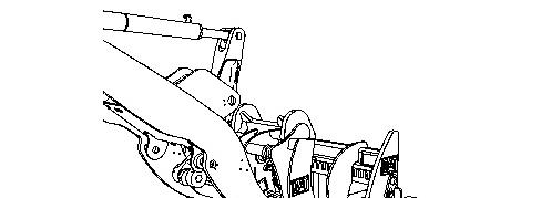
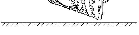
3. Tilt the coupler forward. Ensure that the coupler is below the hooks on the fork. Refer to illustration 1.
4. Slowly drive the machine FORWARD. Center the coupler between the hooks on the fork.
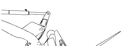
Illustration 2 g01563141
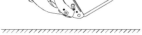
5. Raise the coupler until the coupler comes in contact with the hooks on the fork. Continue to slowly raise the coupler until the fork begins to lift. Ensure that the fork has remained level. Refer to illustration 2.
6. Tilt the coupler backward until the fork fully contacts the coupler. Refer to illustration 3.
7. Move the quick coupler switch to the Lock or Engage position.
If the coupler is controlled by the 3rd Auxiliary Hydraulic Control Lever, move the control forward to the Lock or Engage position. Refer to the Operation and Maintenance Manual of the host machine for additional information on controls.
Inspect the quick coupler engagement before operating the machine.
Serious injury or death may result from improperly engaged coupler.
This is the sample of the sample click on the download link for complete manual
For some reason if link deos not work download this pdf and then click