
Product: TRACK LOADER
Model: 953C TRACK LOADER 2ZN
Configuration: 953C Track-Type Loader Hydrostatic Drive 2ZN01750-UP (MACHINE) POWERED BY 3116 Engine
Disassembly and Assembly
953C Track-Type Loader Machine Systems
Media Number -SENR1773-02
Publication Date -01/05/2006 Date Updated -15/05/2006
Air Conditioner Belt - Remove and Install
SMCS - 1357-010
Remove the Air Conditioner Belt
Start By:
A. Remove the alternator belt.

1
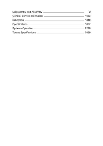
1. Loosen bolt (1) .
2. Loosen bolt (2) and relieve the tension on the belt. Remove air conditioner belt (3) .
Install the Air Conditioner Belt
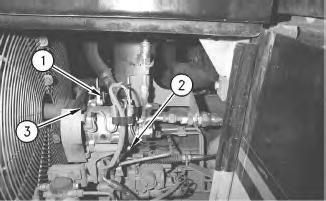
Illustration 2
1. Install air conditioner belt (3). Tighten bolt (2) .
2. Put the correct amount of tension on the air conditioner belt and tighten bolt (1) .
Note: Refer to Operation and Maintenance Manual, SEBU7115 for the correct belt tension.
End By: Install the alternator belt.
Copyright 1993 - 2020 Caterpillar Inc. All Rights Reserved. Private Network For SIS Licensees.
Product: TRACK LOADER
Model: 953C TRACK LOADER 2ZN
Configuration: 953C Track-Type Loader Hydrostatic Drive 2ZN01750-UP (MACHINE) POWERED BY 3116 Engine
Disassembly and Assembly
953C Track-Type Loader Machine Systems
Media Number -SENR1773-02
Publication Date -01/05/2006 Date Updated -15/05/2006
i02541177
Blower Motor (Air Conditioner and Heater) - Remove and Install
SMCS - 7304-010-FM; 7309-010-FM; 7320-010-FM
Removal Procedure
Start By:
A. Remove the seat. Refer to Disassembly and Assembly, "Seat - Remove and Install".

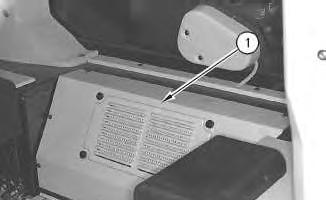
Illustration 1
1. Remove the seven screws in order to remove cover (1). Cover (1) is located behind the seat.
2
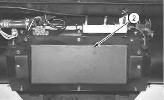
2. Remove the ten bolts, the ten washers and cover (2) .
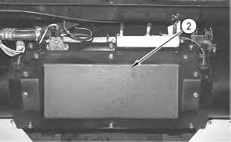
3
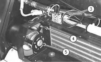
3. Disconnect harnessassembly (3) .
4. Remove three nuts(4) and the three washers. Remove the blower fan and blower fan motor (5) .
Installation Procedure
4
1. Position blower fan motor (5) and the blower fan. Install three nuts (4) and the three washers.
2. Connect harness assembly (3) .
5
3. Position cover (2) and install the ten washers and the ten bolts.
6
4. Position cover (1) and install the seven screws.
End By: Install the seat. Refer to Disassembly and Assembly, "Seat - Remove and Install". Copyright 1993 - 2020 Caterpillar Inc.
Product: TRACK LOADER
Model: 953C TRACK LOADER 2ZN
Configuration: 953C Track-Type Loader Hydrostatic Drive 2ZN01750-UP (MACHINE) POWERED BY 3116 Engine
Disassembly and Assembly
953C Track-Type Loader Machine Systems
Media Number -SENR1773-02 Publication Date -01/05/2006 Date Updated -15/05/2006
Bucket - Remove and Install
SMCS - 6101-010
Removal Procedure Table 1
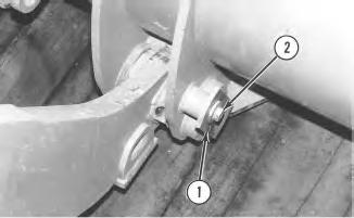
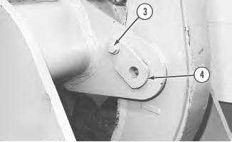
Note: The bucket should be level and the bucket should be under no pressure when the pins are removed.
1. Remove bolts (2) from bucket pins (1) on each arm.
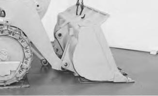
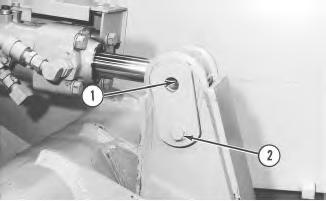
Illustration 2
2. Attach a suitable lifting device to the bucket.
Note: Use Tooling (A) in order to remove the pin, if the pin is tight.
3. Remove the bolt and the pin in order to disconnect the bucket from the Z-bar linkage.
4. Remove the bucket. The weight of the bucket is approximately 780 kg (1720 lb).
Installation Procedure
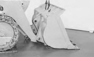
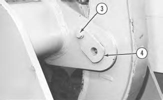
Illustration 3
1. Attach a suitable lifting device to the bucket.
2. Put the bucket into position. The weight of the bucket isapproximately 780 kg (1720 lb).
3. Install the bolt and the pin in order to connect the bucket to the Z-bar linkage.

4
4. Install bolts (2) onto bucket pins (1) on each arm. Tighten bolts(2) to a torque of 360 ± 50 N·m (266 ± 37 lb ft). Install the grease fittings into the pins and use a grease gun in order to put new grease in the pins.
Copyright 1993 - 2020 Caterpillar Inc. All Rights Reserved. Private Network For SIS Licensees.
Product: TRACK LOADER
Model: 953C TRACK LOADER 2ZN
Configuration: 953C Track-Type Loader Hydrostatic Drive 2ZN01750-UP (MACHINE) POWERED BY 3116 Engine
Disassembly and Assembly
953C Track-Type Loader Machine Systems
Media Number -SENR1773-02
Publication Date -01/05/2006 Date Updated -15/05/2006
Bucket Lever and Link - Assemble
SMCS - 6107-016
Assembly Procedure Table 1 RequiredTools

Illustration 1
i02546042
g00474239
1. Put clean grease on the bearings. Use Tooling (A) and a pressin order to install bearing (6) into the lever. Install seals (5) into the lever.

Illustration 2 g00474238
2. Use Tooling (A) and a press in order to install bearings (4) in both ends of the link. Install seal (3) in both ends of the link.
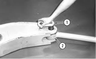
Illustration 3
g00474236
3. Install link (2) into the lever. Install pin (1) into the lever. Install the bolt that holdspin (1) in place. Tighten the bolt to a torque of 360 ± 50 N·m (266 ± 37 lb ft).
End By: Install the bucket lever and the link. Refer to Disassembly and Assembly, "Bucket Lever and Link - Install".
Copyright 1993 - 2020 Caterpillar Inc. All Rights Reserved. Private Network For SIS Licensees. Mon Feb 24 23:31:02 UTC+0530 2020
Product: TRACK LOADER
Model: 953C TRACK LOADER 2ZN
Configuration: 953C Track-Type Loader Hydrostatic Drive 2ZN01750-UP (MACHINE) POWERED BY 3116 Engine
Disassembly and Assembly
953C Track-Type Loader Machine Systems
Media Number -SENR1773-02
Publication Date -01/05/2006 Date Updated -15/05/2006
Bucket Lever and Link - Disassemble
SMCS - 6107-015
Disassembly Procedure Table 1 RequiredTools
i02546014
Start By:
A. Remove the bucket lever and the link. Refer to Disassembly and Assembly, "Bucket Lever and Link - Remove". Illustration 1
1. Remove the bolt that holds pin (1) in place. Remove pin (1) from the lever. Remove link (2) from the lever.
Illustration 2
2. Remove seal (3) from both ends of the link. Use Tooling (A) and a press in order to remove bearings (4) from both ends of the link.
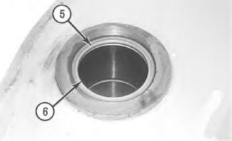
Illustration 3
g00474239
3. Remove seals (5) from the lever. Use tooling (A) and a press in order to remove bearing (6) from the lever.
Product: TRACK LOADER
Model: 953C TRACK LOADER 2ZN
Configuration: 953C Track-Type Loader Hydrostatic Drive 2ZN01750-UP (MACHINE) POWERED BY 3116 Engine
Disassembly and Assembly
953C Track-Type Loader Machine Systems
Media Number -SENR1773-02
Publication Date -01/05/2006 Date Updated -15/05/2006
Bucket Lever and Link - Install
SMCS - 6107-012
Install the Bucket Lever and the Link
1
1. Fasten a hoist to the bucket lever. Install the bucket lever and the link to the lift arms. The weight of the bucket lever and link is 207 kg (456.4 lb).
2. Install bolt (3) and pin (4) into the bucket lever. Tighten the bolt to a torque of 360 ± 50 N·m (265.5 ± 36.9 lb ft).
3. Fasten a hoist to the tilt cylinder. Put the tilt cylinder in place. Install the pin into the bucket lever. Install bolt (2) that holds the pin in place. Tighten the bolt to a torque of 360 ± 50 N·m (265.5 ± 36.9 lb ft). Install grease fitting (1) in the pin. Use a grease gun in order to put newgrease in the pinsafter the pins are installed.
End By: Install the bucket.
Copyright 1993 - 2020 Caterpillar Inc. All Rights Reserved. Private Network For SIS Licensees.
Product: TRACK LOADER
Model: 953C TRACK LOADER 2ZN
Configuration: 953C Track-Type Loader
Disassembly and Assembly
953C Track-Type Loader Machine Systems Media
Bucket Lever and Link - Remove SMCS - 6107-011
Removal Procedure Table 1 Required Tools
Start By:
1. Start the machine. Extend or retract the tilt cylinder until the bucket lever is vertical.

1
2. Attach a suitable lifting device to the tilt cylinder. Remove grease fitting (1) from the pin. Remove bolt (2) that holds the pin in place. Remove the pin from the bucket lever. Use Tooling (B) in order to remove the pin, if the pin is tight. Lower the tilt cylinder so that the rod of the cylinder is against the lift arms.
2
3. Attach a suitable lifting device to the bucket lever. Remove bolt (3) and pin (4) from the bucket lever. Use Tooling (B) in order to remove the pin, if the pin istight.
4. Remove the bucket lever and the link from the lift arms. The weight of the bucket lever and link is approximately 207 kg (456 lb). Copyright 1993 - 2020 Caterpillar Inc.
Product: TRACK LOADER
Model: 953C TRACK LOADER 2ZN
Configuration: 953C Track-Type Loader Hydrostatic Drive 2ZN01750-UP (MACHINE) POWERED BY 3116 Engine
Disassembly and Assembly
953C Track-Type Loader Machine Systems
Media Number -SENR1773-02
Publication Date -01/05/2006 Date Updated -15/05/2006
Bumper - Remove and Install
SMCS - 7156-010
Removal Procedure Table 1
Required Tools Tool Part Number Description
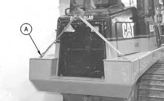
Illustration 1 g00470308
1. Attach Tooling (A) and a suitable lifting device to the bumper.
i02548669
2
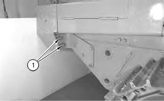
2. Remove bolts (1) and the washersfrom both sides of the bumper. Remove the bumper. The weight of the bumper is approximately 544 kg (1200 lb).
Installation Procedure
Table 2
Required Tools
Tool Part Number Description Qty
A 138-7574 Link Bracket 1
Illustration 3
1. Attach Tooling (A) and a suitable lifting device to the bumper, asshown.
2. Position the bumper. The weight of the bumper is approximately 544 kg (1200 lb). Install bolts (1) and the two washers in both sides of the bumper.
Copyright 1993 - 2020 Caterpillar Inc. All Rights Reserved. Private Network For SIS Licensees. Mon Feb 24 23:45:16 UTC+0530 2020
Product: TRACK LOADER
Model: 953C TRACK LOADER 2ZN
Configuration: 953C Track-Type Loader Hydrostatic Drive 2ZN01750-UP (MACHINE) POWERED BY 3116 Engine
Disassembly and Assembly
953C Track-Type Loader Machine Systems
Media Number -SENR1773-02 Publication Date -01/05/2006 Date Updated -15/05/2006
Cab - Install
SMCS - 7325-012
Installation Procedure Table 1 RequiredTools Tool Part Number Part Description Qty A 138-7575 Link Bracket 4
Personal injury can result from air conditioning system pressure.
The air conditioning system will become a pressure system when charged.
To avoid personal injury see the Air Conditioning and Heating Service Manual for instructions on charging the system.
Personal injury or death can result from inhaling refrigerant througha lit cigarette.
Inhaling air conditioner refrigerant gasthrough a lit cigarette or other smoking method or inhaling fumesreleasedfrom a flame contacting air conditioner refrigerant gas, cancause bodily harm or death.
Do not smoke when servicing air conditioners or wherever refrigerant gas may be present.
Personal injury or death can result when charging an air conditioning system with a liquid.
The compressor will pumpthe refrigerant back into the charging cylinder with the possibility of rupturing (exploding) the cylinder.
Do not operate the engine when charging with a liquid.
Never charge liquid or gas through the discharge (high side of the system) with the engine running.
Keep all other personnel either away from the machine or where they canbe seenwhen working on the air conditioning system.
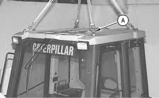
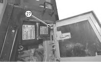
Illustration 2
2. Position the cab. The weight of the cab is approximately 1035 kg (2277 lb). Install rear mounting bolts (27) on both sides of the cab.
3. Install cab mounting bolts. Tighten cab mounting bolts to a torque of 850 ± 100 N·m (627 ± 74 lb ft).
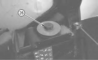
Illustration 3
g00470117
4. Install front mounting bolts (26) on both sidesof the cab.
5. Install cab mounting bolts. Tighten cab mounting bolts to a torque of 850 ± 100 N·m (627
ft).

Illustration 4 g00470114
6. Position cover (25) and two allen head screws(24) on both sides of the machine.
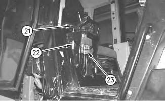
5
7. Pull the cable through the hole in the floor and install locknut (22). Install knob (21) on the control rod.
8. Connect eight hoses (23) .
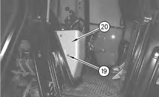
6
9. Position cover (20) and four allen head screws(19) .
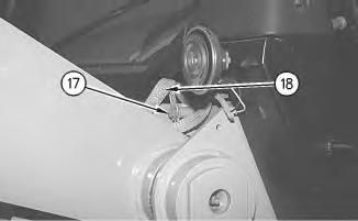
Illustration 7
10. Install ground strap (18) and bolt (17) .
g00470085
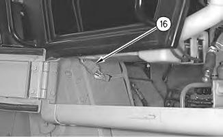
Illustration 8
11. Connect harness assembly (16) .
g00470082
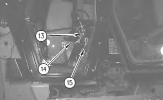
Illustration 9
g00469968
12. Pull cable through the hole in the cab and tighten nut (15) .
13. Connect cable (13) to lever (14) .