
Note: Use Bookmarks panel to navigate
This is the sample of the manual click on the download link for complete manual
Note: Use Bookmarks panel to navigate
This is the sample of the manual click on the download link for complete manual
For some reason if link does not work download this pdf and then click

Product: WHEEL LOADER
Model: 950M Z WHEEL LOADER HE8
Configuration: 950M Z Wheel Loader HE800001-UP (MACHINE)
Disassembly and Assembly 950M, 962M, 950M Z and 962M Z Wheel Loaders
SMCS - 1000-010; 1002
Removal Procedure Table 1 Required Tools
Start By:
a. Remove the cooling system package.
b. Remove the hydraulic tank.
c. Remove the clean emissions module.
Personal injury can result from contact with refrigerant.
Contact with refrigerant can cause frost bite. Keep face and hands away to help prevent injury.
Protective goggles must always be worn when refrigerant lines are opened, even if the gauges indicate the system is empty of refrigerant.
Always use precaution when a fitting is removed. Slowly loosen the fitting. If the system is still under pressure, release it slowly in a well ventilated area.
Personal injury or death can result from inhaling refrigerant through a lit cigarette.
Inhaling air conditioner refrigerant gas through a lit cigarette or other smoking method or inhaling fumes released from a flame contacting air conditioner refrigerant gas, can cause bodily harm or death.
Do not smoke when servicing air conditioners or wherever refrigerant gas may be present.
Use a certified recovery and recycling cart to properly remove the refrigerant from the air conditioning system.
1. Recover the refrigerant. Refer to Service Manual, SENR5664, "All Products Air Conditioning and Heating R134a for All Caterpillar Machines" for the recovery and charging procedure. Refer to Special Publication, NENG2500, "Air Conditioning Tools" for the correct tools.
1
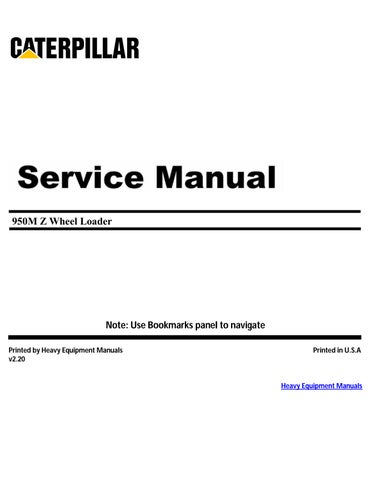
2. Disconnect hose assemblies (1) from the fan brake pump.
2
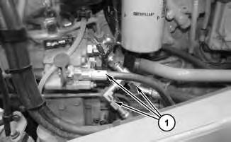
3. Reposition support (2) out of the way.
3
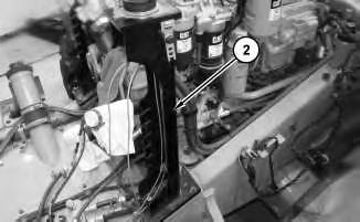
4. Disconnect hose assembly (3) and hoses (4).
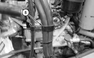
Illustration 4
5. Remove both clips (5).
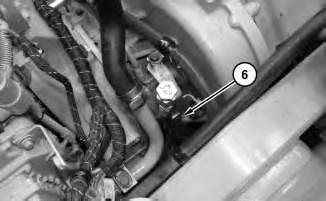
Illustration 5
g03692113
View of upper right-hand side of the transmission to engine connection.
6. Remove clip (6).
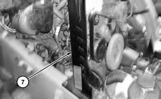
Illustration 6
7. Remove support (7).
g03692117
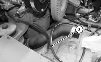
Illustration 7
8. Disconnect hose (8).
g03692138
8
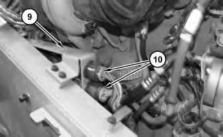
9. Disconnect harness assemblies (10) from both sides of bracket (9). Remove bracket (9).

Illustration 9
g03692175
10. Disconnect hose assemblies (11). Disconnect harness assemblies (12).
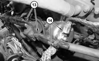
Illustration 10
g03692197
11. Disconnect cable assemblies (13) and ground straps (14) from the electronic starting motor.
11
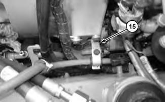
12. Disconnect bracket (15) from the bell housing.
12
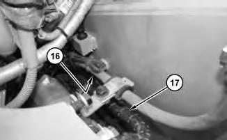
13. Disconnect clip (16) on harness assembly (17).

Illustration 13
14. Disconnect clips (18) and reposition hose assemblies (19).

Illustration 14
View from under the flywheel housing.
g03692397
15. Disconnect clip (20) from the flywheel housing.
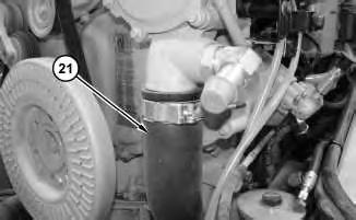
Illustration 15
16. Disconnect hose (21).
g03692500
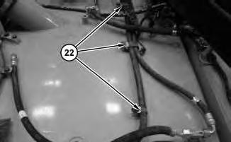
Illustration 16
17. Disconnect clips (22).
g03693280
17
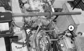
18. Attach Tooling (A) to the torque converter housing in order to support that side of the transmission when the engine is removed.
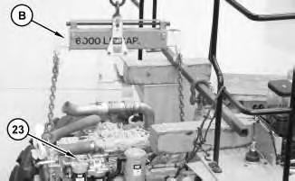
Illustration 18
19. Attach Tooling (B) and a suitable lifting device to engine (23). The weight of engine (23) is approximately 816 kg (1800 lb).
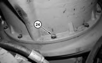
Illustration 19
g03693444 View from underneath the flywheel housing.
20. Remove bolts (24).
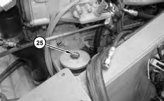
Illustration 20
g03693432

Illustration 21
21. Remove mount bolts (25) and (26).
g03693436
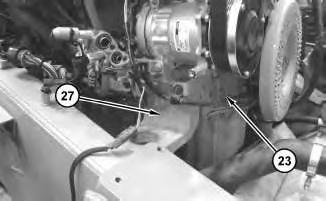
Illustration 22
g03693458
22. Remove engine mount (27) and remove engine (23).
1. Install engine (23) in the reverse order of removal.
a. Tighten bolts (25) and (26) to a torque of 520 ± 70 N·m (383 ± 52 lb ft).
b. Tighten bolts (24) to a torque of 70 ± 15 N·m (52 ± 11 lb ft).
Copyright 1993 - 2023 Caterpillar Inc. All Rights Reserved. Private Network For SIS Licensees.
Sun Nov 12 11:45:53 UTC+0530 2023
Product: WHEEL LOADER
Model: 950M Z WHEEL LOADER HE8
Configuration: 950M Z Wheel Loader HE800001-UP (MACHINE) POWERED BY C7.1 Engine
Disassembly and Assembly
950M, 962M, 950M Z and 962M Z Wheel Loaders Media Number -UENR3108-05
SMCS - 1802-010
Removal Procedure
Personal injury can result from contact with refrigerant.
Contact with refrigerant can cause frost bite. Keep face and hands away to help prevent injury.
Protective goggles must always be worn when refrigerant lines are opened, even if the gauges indicate the system is empty of refrigerant.
Always use precaution when a fitting is removed. Slowly loosen the fitting. If the system is still under pressure, release it slowly in a well ventilated area.
Personal injury or death can result from inhaling refrigerant through a lit cigarette.
Inhaling air conditioner refrigerant gas through a lit cigarette or other smoking method or inhaling fumes released from a flame contacting air conditioner refrigerant gas, can cause bodily harm or death.
Do not smoke when servicing air conditioners or wherever refrigerant gas may be present.
Use a certified recovery and recycling cart to properly remove the refrigerant from the air conditioning system.
Do not use Polyalkylene Glycol (PAG) oil in the compressor. Use Polyol Ester (POE) oil. The use of any other oil will cause rapid dielectric failure of the compressor.
1. Raise the engine hood.
2. Turn the battery disconnect to the off position.
3. Remove the panel on the left side of the engine.
4. Recover the refrigerant. Refer to Service Manual, SENR5664, "Air Conditioning and Heating R-134a Refrigerant for All Caterpillar Machines" for the recovery and the charging procedure. Refer to Special Publication, NENG2500, "Air Conditioning Tools" for the correct tools.
5. Remove the serpentine belt. Refer to Operation and Maintenance Manual, "Belts - Inspect / Adjust / Replace".
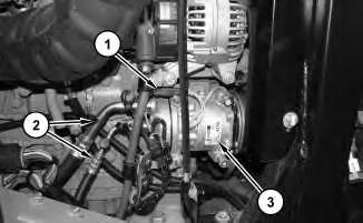
Illustration 1
g03696732 Typical example.
6. Disconnect harness assembly (1).
7. Disconnect hose assemblies (2).
8. Remove refrigerant compressor (3).
1. Install refrigerant compressor (3) in the reverse order of removal.
Product: WHEEL LOADER
Model: 950M Z WHEEL LOADER HE8
Configuration: 950M Z Wheel Loader HE800001-UP (MACHINE) POWERED BY C7.1 Engine
Disassembly and Assembly
950M, 962M, 950M Z and 962M Z Wheel Loaders
Media Number -UENR3108-05
SMCS - 1051-010
Hot engine components can cause injury from burns. Before performing maintenance on the engine, allow the engine and the components to cool.
1. Raise the engine hood.
2. Turn the battery disconnect to the off position.
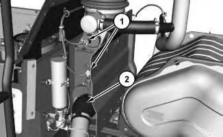
Illustration 1 g03696631
3. Disconnect hose (2) and harness assemblies (1).
2
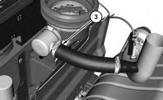
4. Disconnect hose (3).
3
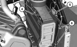
5. Remove cable strap (4) from the harness assembly . Disconnect module (5) and reposition out of the way. Remove cable straps (6) from the harness assembly.
4
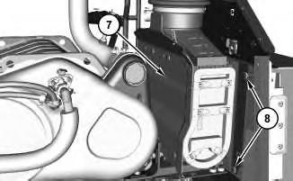
6. Remove bolts (8) from both sides. Remove air cleaner assembly (7).
Installation Procedure
1. Install air cleaner assembly (7) in the reverse order of removal.
Copyright 1993 - 2023 Caterpillar Inc. All Rights Reserved. Private Network For SIS Licensees.
Sun Nov 12 11:45:25 UTC+0530 2023
Product: WHEEL LOADER
Model: 950M Z WHEEL LOADER HE8
Configuration: 950M Z Wheel Loader HE800001-UP (MACHINE) POWERED BY C7.1 Engine
Disassembly and Assembly
950M, 962M, 950M Z and 962M Z Wheel Loaders
Media Number -UENR3108-05
Publication Date -01/08/2014 Date Updated -08/05/2019
SMCS - 1052-012
Installation Procedure Table 1
Required Tools
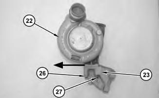
Illustration 1
i06515038
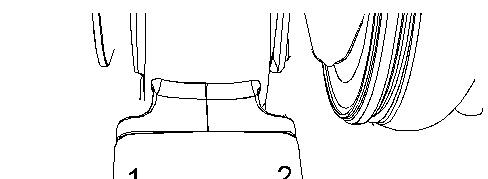
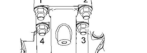

Illustration 2 g02682676
Torque sequence
1. Ensure that second stage turbocharger (22) is clean and free from damage. Inspect the turbocharger for wear. Refer to System Operation, Testing and Adjusting, "Turbocharger Inspect" for more information. If any part of the turbocharger is worn or damaged, the complete turbocharger must be replaced.
2. If necessary, install studs (27) in second stage turbocharger (22). Tighten studs (27) to a torque of 18 N·m (159 lb in).
3. Position bracket (23) on second stage turbo (22).
4. Loosely install nuts (26).
Note: Bracket (23) must be able to move freely to allow correct positioning.
5. Apply sufficient pressure to second stage turbocharger (22) in the direction of arrow. Do not release the pressure on the turbocharger in the direction shown until nuts (26) have been tightened.
6. Tighten nuts (26) to a torque of 44 N·m (32 lb ft) in the sequence shown.
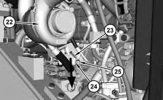
Illustration 3
g02682837
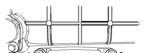


Illustration 4 g02682917
second stage turbo removed for clarity
7. Position second stage turbocharger (22) and bracket (23) on studs (24).
8. Loosely install nuts (25) on studs (24).
Note: Bracket (23) must be able to move freely to allow correct positioning.
9. Apply sufficient pressure to second stage turbo (22) and bracket (23) in the direction shown in illustration 4. Ensure second stage turbo (22) and bracket (23) are at the lowest point on
studs (24). Do not release the pressure on second stage turbocharger (22) and bracket (23) in the direction shown until nuts (25) have been tightened.
10. Tighten nuts (25) to a torque of 44 N·m (33 lb ft) in the sequence shown in Illustration 4.
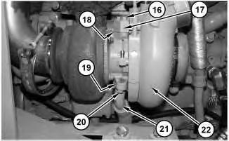
Illustration 5
11. Position a new gasket (19) and tube assembly (21). Install bolts (20). Tighten bolts (20) to a torque of 22 N·m (195 lb in).
12. Position a new gasket (18) and tube assembly (17) on second stage turbocharger (22). Install bolts (16). Tighten bolts (16) to a torque of 22 N·m (195 lb in).
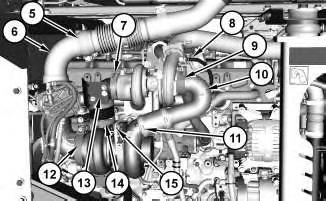
Illustration 6
13. Position tube assembly (10) Use Tooling (A) to lubricate the allen head bolt for clamp (9). Position clamp (9) on tube assembly (10). Tighten the allen head bolt for clamp (9) to a torque of 12 ± 1 N·m (106 ± 8.9 lb in).
14. Tighten hose clamps (11) to a torque of 6 N·m (53 lb in).
15. Connect hose (8) and tube (15).
16. Use Tooling (A) to lubricate the allen head bolt for clamp (7) and clamp (14).
17. Position elbow (13).
18. Tighten allen head bolt for clamp (7) and clamp (14) finger tight. Ensure that the clamps are seated correctly onto the turbochargers.
19. Tighten allen head bolts for clamp (7) and clamp (14) to a torque of 12 N·m (106 lb in).
20. Position tube assembly (6) and install a new clamp (5). Tighten clamp (5) to the following torque 35 ± 2 N·m (26 ± 1 lb ft). Use Tooling (A) to lubricate the allen head bolt for clamp (12). Tighten allen head bolt for clamp (12) to a torque of 22 N·m (195 lb in).
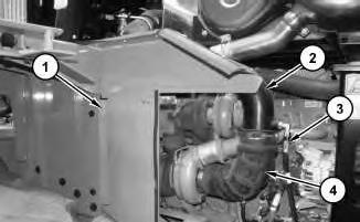
21. Install tube assembly (2) and hose (4). Connect hose assembly (3) and panel (1).
22. Install the engine panels on the left-hand side of the engine.
23. Turn the disconnect switch to the ON position.
24. Lower the hood.
Product: WHEEL LOADER
Model: 950M Z WHEEL LOADER HE8
Configuration: 950M Z Wheel Loader HE800001-UP (MACHINE) POWERED BY C7.1 Engine
Disassembly and Assembly
950M, 962M, 950M Z and 962M Z Wheel Loaders
Media Number -UENR3108-05
SMCS - 1052-012
Installation Procedure Table 1
Required Tools
Hot oil and components can cause personal injury.
Do not allow hot oil or components to contact the skin.
Be sure that the engine and components are cool enough to touch with your bare hand prior to performing any service work.
1. Raise the hood
2. Turn the disconnect switch to the OFF position.
3. Remove the engine panels from the left-hand side of the engine.
Note: Put orientation and location marks on all components for installation purposes.
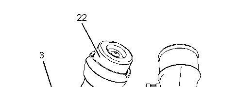
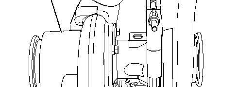

Illustration 1 g01974473
4. Ensure that turbocharger (3) is clean and free from damage. Inspect the turbocharger for wear. Refer to System Operation, Testing and Adjusting, "Turbocharger Inspect" for more information. If any part of the turbocharger is worn or damaged, the complete turbocharger must be replaced.
5. Test wastegate actuator (22) for correct operation. Refer to System Operation, Testing and Adjusting, "Turbocharger Inspect". If any part of the wastegate actuator is worn or damaged, the complete turbocharger must be replaced.
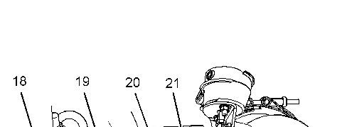
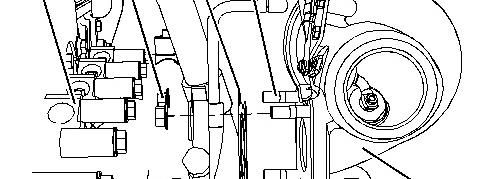
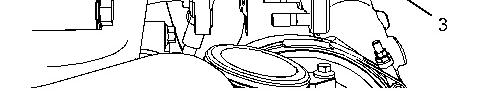
Illustration 2 g01974333
6. Clean the gasket surface of exhaust manifold (18). If necessary, install studs (21) to turbocharger (3). Tighten the studs to a torque of 18 N·m (160 lb in).
7. Install a new gasket (20) to studs (21).
8. Position turbocharger (3) onto the exhaust manifold and loosely install nuts (19).
Note: Ensure that the turbocharger is correctly oriented.
This is the sample of the manual click on the download link for complete manual
For some reason if link does not work download this pdf and then click