DOWNLOAD LINK
For some reason if link does not work download this pdf and then click
Product: WHEEL LOADER
Model: 950K WHEEL LOADER FER
Configuration: 950K Wheel Loader FER00001-UP (MACHINE) POWERED BY C7.1 Engine
Disassembly and Assembly
950K and 962K Wheel Loaders C7.1 Engine Supplement
Media Number -KENR5788-00
Steering Frame Lock - Separate and Connect
SMCS - 7506-029
Connection Procedure
Personal injury or death can result from machine articulation or movement.
Machine frames can move and a person can be crushed.
Connect the steering frame lock link between the front and rear frames before working on machine. Secure clevis pin with locking pin.
Before operating the machine, fasten the steering frame lock link into the stored position and secure the clevis pin with locking pin.
Failure to lock into the stored position before operating can result in loss of steering.
1. Move the machine to a hard, level surface. Park the machine in the straight ahead position and engage the parking brake.
i04416513
1
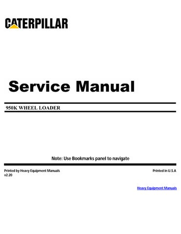
2. Remove locking pin (2) from pin (1).
2
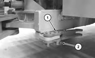
3. Position steering frame lock (3) to the front frame. Install pin (1) and locking pin (2).
Note: To align the pin bores, move the front loader frame.
Separation Procedure
Personal injury or death can result from machine articulation or movement.
Machine frames can move and a person can be crushed.
Connect the steering frame lock link between the front and rear frames before working on machine. Secure clevis pin with locking pin.
Before operating the machine, fasten the steering frame lock link into the stored position and secure the clevis pin with locking pin.
Illustration
g02615257
Illustration
g02614798
Failure to lock into the stored position before operating can result in loss of steering.
Illustration 3
g02614798
1. Remove locking pin (2) and pin (1). Move steering frame lock (3) to the storage position.
Illustration 4
2. Install pin (1) and locking pn (2).
g02615257
Copyright 1993 - 2024 Caterpillar Inc. All Rights Reserved. Private Network For SIS Licensees. Sun Oct 20 11:50:30 UTC+0530 2024
Product: WHEEL LOADER
Model: 950K WHEEL LOADER FER
Configuration: 950K Wheel Loader FER00001-UP (MACHINE) POWERED BY C7.1 Engine
Disassembly and Assembly
950K and 962K Wheel Loaders C7.1 Engine Supplement Media Number -KENR5788-00
System Pressure - Release
SMCS - 4250-553-PX; 4300-553-PX; 5050-553-PX
Machine Preparation
Personal injury can result from hydraulic oil pressure and hot oil.
Hydraulic oil pressure can remain in the hydraulic system after the engine has been stopped. Serious injury can be caused if this pressure is not released before any service is done on the hydraulic system.
Make sure all of the work tools have been lowered to the ground, and the oil is cool before removing any components or lines. Remove the oil filler cap only when the engine is stopped, and the filler cap is cool enough to touch with your bare hand.
Escaping fluid under pressure, even a pinhole size leak, can penetrate body tissue, causing serious injury, and possible death. If fluid is injected into your skin, it must be treated immediately by a doctor familiar with this type of injury.
Always use a board or cardboard when checking for a leak.
i04417880
NOTICE
Care must be taken to ensure that fluids are contained during performance of inspection, maintenance, testing, adjusting, and repair of the product. Be prepared to collect the fluid with suitable containers before opening any compartment or disassembling any component containing fluids.
Refer to Special Publication, NENG2500, "Dealer Service Tool Catalog" for tools and supplies suitable to collect and contain fluids on Cat products.
Dispose of all fluids according to local regulations and mandates.
1. Refer to Testing and Adjusting, "Machine Preparation for Troubleshooting" for the machine that is being serviced before performing the following procedure.
Release System Pressure
1. Move the machine to a location that is smooth, level, and hard. The location should also be dry and free of debris. Stop the engine.
2. Permit only one operator on the machine. All other personnel should be kept away from the machine.
3. If the machine is equipped with a ride control system, move the ride control switch to the SERVICE position. Illustration 1
4. Position the bucket or work tool just above the ground at a slight downward angle. This position will ensure that the head end of the lift cylinders is pressurized.
5. Engage the parking brake.
6. Turn the engine start switch to the OFF position.
7. When the engine has stopped, turn the engine start switch back to the ON position so the pilot oil can reach the main valve.
8. Move the implement lockout switch to the UNLOCKED position.
9. Move the lift control lever to the FLOAT position and the tilt control lever to the TILT BACK position at the same time. This action allows the bucket or the work tool to tilt back while the boom is lowered.
The bottom of the bucket or the work tool should rest flat on the ground. The weight of the linkage should be supported by the ground. The pressure from the head end of the lift cylinders and from the ride control accumulator is now vented to the hydraulic tank.
10. When the bucket or the work tool has settled to the ground, move both control levers to the HOLD position. Then, repeatedly cycle the control levers through all positions in order to purge any remaining pressure from the implement hydraulic system.
11. Turn the steering wheel several times in both directions in order to relieve the pressure in the steering system. To release the pressure from steering cylinders on machines equipped with joystick steering, the machine must not be operated for a minimum of 10 minutes. 10 minutes will allow sufficient time for the pressure in the steering system to dissipate.
12. Turn the engine start switch to the OFF position.
13. Depress the brake pedal repeatedly. This step will relieve any pressure that may be present in the braking system.
14. Push in the plunger for the hydraulic tank breaker relief valve until all pressure is released.
Note: If the machine is not equipped with a hydraulic tank breaker relief valve, remove the hydraulic tank cap slowly to relieve tank pressure.
Dead Electronics
1. If the electronics fail, all stored hydraulic oil pressure may not be relieved. The following precautions should be taken.
2. Turn the engine OFF.
3. The machine should be secured with a lockout.
4. Use the appropriate stand or blocks to prevent undesired drift of implements.
5. Barriers should be used in order to prevent personnel from entering areas that implement drift or movement could be hazardous.
6. To lower lift arms and the ripper onto the ground or onto the appropriate supports, open the 112-1817 Manual Valve Gp.
7. Do not open or disassemble any hydraulic circuits until the electronic controls are restored to relieve stored hydraulic pressure.
Copyright 1993 - 2024 Caterpillar Inc. All Rights Reserved. Private Network For SIS Licensees.
Sun Oct 20 11:50:41 UTC+0530 2024
Product: WHEEL LOADER
Model: 950K WHEEL LOADER FER
Configuration: 950K Wheel Loader FER00001-UP (MACHINE) POWERED BY C7.1 Engine
Disassembly and Assembly
950K and 962K Wheel Loaders C7.1 Engine Supplement Media
Hood - Remove and Install
SMCS - 7251-010
Removal Procedure Table 1
Note: Remove Hood fully before any hood panels are removed. Failure to do so may damage to the hood panels.
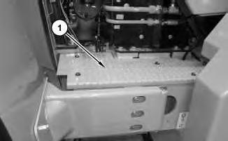
1. Open the rear enclosure.
i04557333
Illustration 1
2. Remove panel (1) .
g02179873
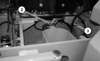
Illustration 2
g02179813
3. Disconnect harness assemblies (2) and remove clip (3) .
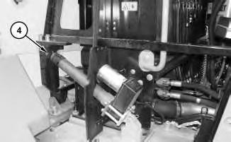
Illustration 3
4. Remove pin (4) .
g02180048
4
Illustration 5
.
Illustration 6
Illustration
g02180051
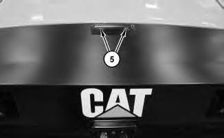
5. Remove bolts (5) .
g02180074
6. Remove plug (6)
g02180093
7. Attach Tooling (B) to the enclosure frame. Attach Tooling (A) to Tooling (B) and to the rear enclosure latch.
Illustration 7
g02724779
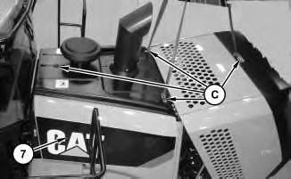
8. Attach Tooling (C) and suitable lifting device to hood assembly (7). The weight of hood assembly (7) is approximately 286 kg (630 lb).
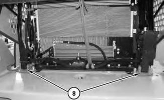
Illustration 8
g02180193
9. Disconnect hinges (8). Remove hood assembly (7) .
Installation Procedure
1. Install hood assembly (7) in the reverse order of the removal. Copyright 1993 - 2024 Caterpillar Inc.
Network For SIS Licensees. Sun Oct 20 11:50:52 UTC+0530 2024
Product: WHEEL LOADER
Model: 950K WHEEL LOADER FER
Configuration: 950K Wheel Loader FER00001-UP (MACHINE) POWERED BY C7.1 Engine
Disassembly and Assembly
950K and 962K Wheel Loaders C7.1 Engine Supplement
Media Number -KENR5788-00 Publication Date -01/09/2011 Date Updated -28/09/2011
Hood Tilt Actuator - Remove and Install
SMCS - 7275-010
Removal Procedure
1. Position the hood in the lower position in order to ensure that there is no tension on the actuator.
2. Open the rear enclosure.
3. Turn the disconnect switch to the OFF position.
Illustration 1
4. Disconnect harness assembly ( 3).
5. Remove pins (1) and (4).
6. Remove hood tilt actuator (4).
Installation Procedure
i04418473
1. Install hood tilt actuator (4) in the reverse order of removal.
Copyright 1993 - 2024 Caterpillar Inc. All Rights Reserved. Private Network For SIS Licensees.
Sun Oct 20 11:51:02 UTC+0530 2024
Product: WHEEL LOADER
Model: 950K WHEEL LOADER FER
Configuration: 950K Wheel Loader FER00001-UP (MACHINE) POWERED BY C7.1 Engine
Disassembly and Assembly
950K and 962K Wheel Loaders C7.1 Engine Supplement
Media Number -KENR5788-00 Publication Date -01/09/2011 Date Updated -28/09/2011
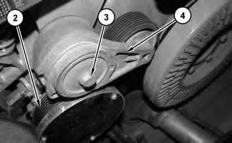
Belt Tensioner - Remove and Install
SMCS - 1358-010
Removal Procedure
1. Open the hood.
2. Turn the battery disconnect switch to the OFF position.
Illustration 1
3. Remove cover (1) .
g02620740
i04419690
4. Remove belt (2). Refer to Operation and Maintenance Manual, "Belts - Inspect / Adjust / Replace".
5. Remove bolt (3) and belt tensioner (4) .
Installation Procedure
1. Install belt tensioner (4) in the reverse order of removal.
Product: WHEEL LOADER
Model: 950K WHEEL LOADER FER
Configuration: 950K Wheel Loader FER00001-UP (MACHINE) POWERED BY C7.1 Engine
Disassembly and Assembly
950K and 962K Wheel Loaders C7.1 Engine Supplement
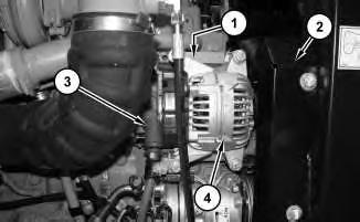
Alternator - Remove and Install
SMCS - 1405-010
Removal Procedure
1. Raise the engine hood.
2. Turn the battery disconnect switch to the OFF position.
3. Open the panel on the left side of the engine.
Illustration 1
g02605038
4. Remove shield assembly (2). Remove the serpentine belt. Refer to Operation and Maintenance Manual, "Belts - Inspect / Adjust / Replace".
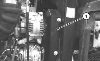
5. Disconnect positive cable assembly (3) .
6. Disconnect negative cable assembly (1) located behind alternator (4) .
7. Remove alternator (4) .
i04408065
Installation Procedure
1. Install alternator (4) in the reverse order of removal.
Copyright 1993 - 2024 Caterpillar Inc. All Rights Reserved. Private Network For SIS Licensees.
Sun Oct 20 11:51:23 UTC+0530 2024
Product: WHEEL LOADER
Model: 950K WHEEL LOADER FER
Configuration: 950K Wheel Loader FER00001-UP (MACHINE) POWERED BY C7.1 Engine
Disassembly and Assembly
950K and 962K Wheel Loaders C7.1 Engine Supplement
Media Number -KENR5788-00 Publication Date -01/09/2011 Date Updated -28/09/2011
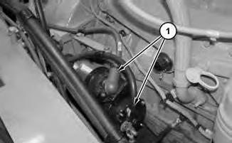
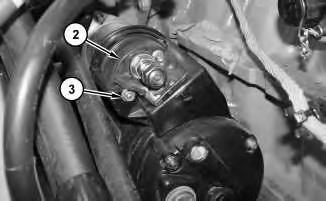
Electric Starting Motor - Remove and Install
SMCS - 1453-010
Removal Procedure
1. Raise the engine hood.
2. Turn the battery disconnect switch to the OFF position.
Illustration 1
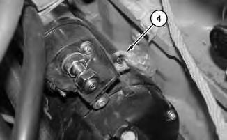
3. Disconnect cable assemblies (1) .
g01176939
i04419715
2
4. Remove nut (3) and cover (2) .
Illustration 3
5. Disconnect wire (4) .
Illustration 4
Illustration
g01176940
g01176941
g01176942
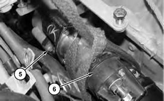
6. Attach a suitable lifting device to electric starting motor (6). The weight of electric starting motor (6) is approximately 25 kg (55 lb).
7. Remove bolts (5) and electric starting motor (6) .
Installation Procedure
1. Install electric starting motor () in the reverse order of removal.
Copyright 1993 - 2024 Caterpillar Inc. All Rights Reserved. Private Network For SIS Licensees. Sun Oct 20 11:51:36 UTC+0530 2024
Product: WHEEL LOADER
Model: 950K WHEEL LOADER FER
Configuration: 950K Wheel Loader FER00001-UP (MACHINE) POWERED BY C7.1 Engine
Disassembly and Assembly
950K and 962K Wheel Loaders C7.1 Engine Supplement
Media Number -KENR5788-00
Primary Fuel Filter, Water Separator and Base - Remove and Install
SMCS - 1260-010; 1261-010; 1262-010; 1263-010
Removal Procedure
Table 1 Required Tools Tool
A 185-3630 Strap Wrench As 1
Start By:
A. Connect the steering frame lock.
1. Raise the engine hood.
2. Remove the panel on the right side of the engine.
i04558653
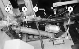
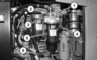
3. Disconnect harness assembly (6). Use Tooling (A) in order to remove the primary fuel filter and water separator (5). Disconnect tube assembly (1), and hose assemblies (2) and (4) .
4. Remove fuel filter base (3) .
Installation Procedure
1. Install fuel filter base (3) and primary fuel filter (5) in the reverse order of removal.
1993 - 2024 Caterpillar Inc.
Product: WHEEL LOADER
Model: 950K WHEEL LOADER FER
Configuration: 950K Wheel Loader FER00001-UP (MACHINE) POWERED BY C7.1 Engine
Disassembly and Assembly
950K and 962K Wheel Loaders C7.1 Engine Supplement Media
Fuel Priming Pump - Remove and Install
SMCS - 1258-010
Removal Procedure
Start By:
A. Connect the steering frame lock.
1. Raise the engine hood.
2. Turn the battery disconnect switch to the off position.
3. Open the engine panel on the right side of the engine.
1
4. Disconnect hose assemblies (1). Disconnect harness assembly (2). Remove fuel priming pump (3) .
i04407814