DOWNLOAD LINK
For some reason if link does not work download this pdf and then click
Illustration 6
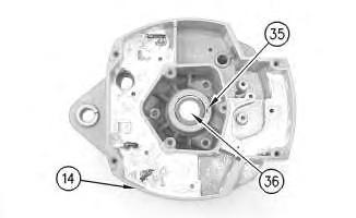
10. Press cap (36) in housing (14) .
g00628043
Illustration 7
g00628041
11. Install the coil and support (34) in housing (14). Guide the field leads and the grommet through the hole as the coil is installed in housing (14). Install 3 screws(33) .
Illustration 8
g00628037
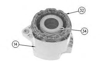
12. Press the stator (32) and housing (14) together. Guide the stator leads and the grommet through the hole as the stator isinstalled in housing (14) .
Illustration 9
g00628035
Note: Do not damage exposed stator windings or field windings. Bumping the windings or scraping the windings may break the insulation. Broken insulation may create a short circuit or a ground.
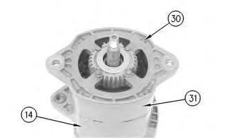
13. Join housing (31) and housing (14). Install 4 bolts (30) .
Illustration 10
g00627853
Note: Many of the alternator's internal components are covered with dielectric grease. If the grease is removed, reapply the grease.
11
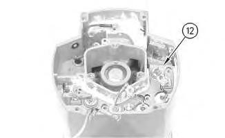
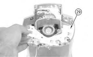
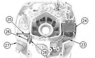
14. Install Insulator (29). Install the heat sink and diode assembly (12) in housing (14) .
12
15. Install separator (28) .
16. Install alternator output terminal (27). Install insulator (26). Install the nut and washer (25) .
17. Install diode trio (24) and install screw(23) .
Illustration
g00627855
Illustration
g00627840
Illustration 13
g00627832
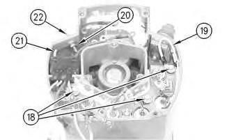
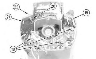
18. Install the 3 screws and insulators (18). Connect wire (19) .
19. If the "R" terminal is used, install the following components: nut (20), lead (21), the washer and terminal (21) .
Illustration 14
g00627820
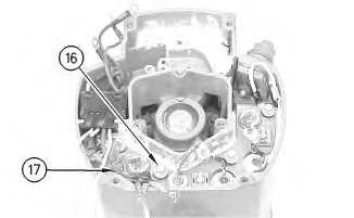
20. Install the screw and insulator (16). Connect capacitor lead (17) .
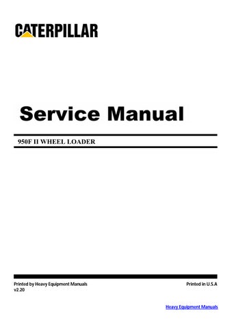
Illustration 15
g00627810
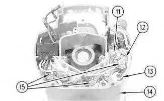
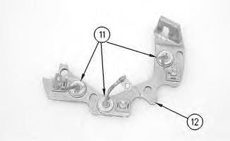
Note: The 3 output diodes (11) are located in heat sink (12). These diodes are identical in polarity. Diode (11) has red insulation on the wire. The 3 ground diodes (13) are located in housing (14). These diodesare identical in polarity. Diode (13) hasblack insulation on the wire.
21. Connect 6 diode leads. Connect 3 phase leads. Connect 3 stator phase leads. Install 3 nuts (15).
Table 1
Alternator Ground
Negative
Current Flow of the Output Diodes
Lead to the Heat Sink
Current Flow of the Ground Diodes
Housing to the Lead Red Wire Black Wire
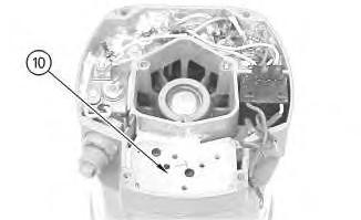
Illustration 16
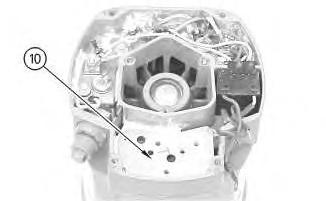
22. Install mounting plate (10).
g00627808
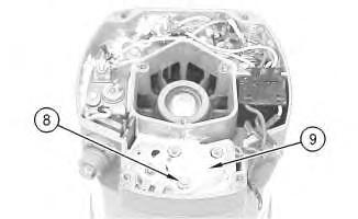
Illustration 17
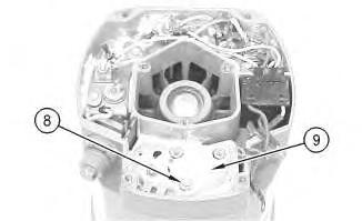
23. Install regulator (9) .
24. Install grounded mounting screw (8) .
g00627804
18
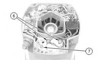
25. Install 2 insulated screws (6). Connect the 3 leads.
Note: The regulator and the mounting plate are coated with dielectric grease. If the grease is removed, reapply the grease.
26. Install nut (7) and connect the wire.
19
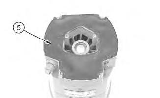
27. Install gasket (5) .
Illustration
g00627796
Illustration
g00627794
20
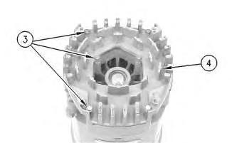
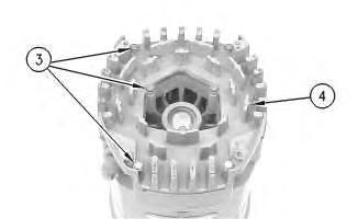
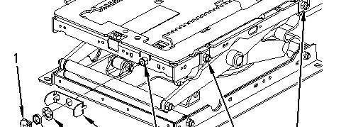
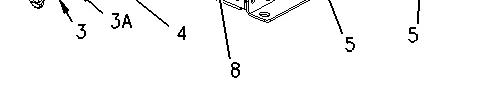
28. Position cover (4). Install 7 screws (3) .
21
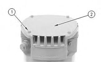
29. Position plate (2). Install 4 screws (1) .
30. Install the fan, the pulley, the washer, and the pulley nut. Copyright 1993 - 2021 Caterpillar Inc. All Rights Reserved. Private Network For SIS Licensees. Wed Feb 10 21:42:26 UTC+0530 2021
Illustration
g00627792
Illustration
g00627790
Product: WHEEL LOADER
Model: 950F II WHEEL LOADER 5SK01561
Configuration: 950F Series II Wheel Loader 5SK00743-UP (MACHINE) POWERED BY 3116 Engine
Disassembly and Assembly
26SI Series Alternator
Media Number -RENR1252-01
Alternator - Disassemble
SMCS - 1405-015
Disassembly Procedure Table 1 Required Tools
i01167081
Start By:
A. Remove the alternator. Refer to Disassembly and Assembly, "Alternator - Remove" for the machine that is being serviced.
Note: Cleanliness is an important factor. Before the disassembly procedure, the exterior of the component should be thoroughly cleaned. This will help to prevent dirt from entering the internal mechanism.
1. Remove the pulley nut, the washer, the pulley, and the fan.
Illustration 1
2. Remove 4 screws (1). Remove plate (2) .
Illustration 2
3. Remove 7 screws (3). Remove cover (4) .
Illustration 3
4. Remove gasket (5) .
g00627790
g00627792
g00627794
Illustration 4
5. Remove 2 insulated screws(6). Remove the 3 leads.
Note: The regulator and the mounting plate are coated with dielectric grease. If the grease is removed, reapply the grease.
6. Remove nut (7) .
Illustration 5
7. Remove grounded mounting screw (8) .
8. Remove regulator (9) .
g00627796
g00627804
Illustration 6
g00627808
9. Remove mounting plate (10). The mounting plate may be stuck to the regulator.
Illustration 7
g00627810
Note: The 3 output diodes (11) are located in heat sink (12). These diodes are identical in polarity. Diode (11) has red insulation on the wire. The 3 ground diodes (13) are located in housing (14). These diodesare identical in polarity. Diode (13) hasblack insulation on the wire.
10. Remove 3 nuts(15). Disconnect 3 stator phase leads. Disconnect 3 phase leads. Disconnect 6 diode leads.
Table 2
Alternator Ground Current Flow of the Output Diodes Current Flow of the Ground Diodes
Negative
Lead to the Heat Sink Housing to the Lead Red Wire Black Wire
Illustration 8
11. Remove the screw and insulator (16). Disconnect capacitor lead (17) .
Illustration 9
g00627832
12. Remove the 3 screws and insulators (18). Disconnect wire (19) .
13. If the "R" terminal is used, remove the following components: nut (20), lead (21), the washer and terminal (21) .
g00627820
Illustration 10
14. Remove screw(23) and remove diode trio (24) .
15. Remove the nut and washer (25). Remove insulator (26). Remove alternator output terminal (27) .
16. Remove separator (28) .
Illustration 11
g00627853
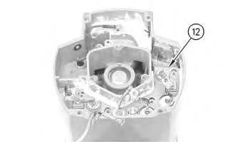
Note: Many of the alternator's internal components are covered with dielectric grease. If the grease is removed, reapply the grease.
Illustration 12
g00627855
17. Remove the heat sink and diode assembly (12) from housing (14). Insulator (29) may be stuck to heat sink (12) .
Illustration 13
g00628035
Note: Do not damage exposed stator windings or field windings. Bumping the windings or scraping the windings may break the insulation. Broken insulation may create a short circuit or a ground.
18. Remove 4 bolts (30). Carefully separate housing (31) from housing (14) .
Illustration 14
g00628037
19. Pull apart stator (32) and housing (14). Guide the stator leads and the grommet through the hole as the stator isremoved from housing (14) .
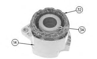
Illustration 15
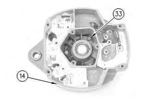
g00628041
20. Remove 3 screws (33). Remove the coil and support (34) from housing (14). Guide the field leads and the grommet through the hole as the coil is removed from housing (14) .
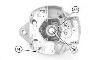
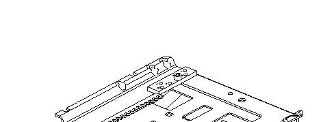
Illustration 16
g00628043
21. Position a small screwdriver in slot (35). Pry cap (36) from housing (14) .
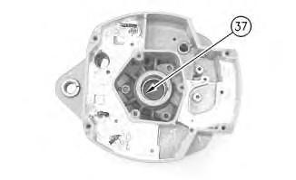
Illustration 17
g00628057
Note: Do not strike the bearing. Shocksfrom striking the housing can cause damage.
22. Wipe the excessgrease from the bearing well. Press bearing (37) into the housing. Remove the inner race.
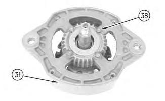
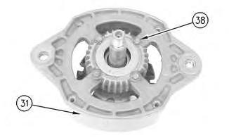
Illustration 18
23. Remove 4 screws (38) from housing (31) .
g00628063
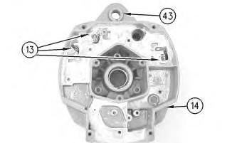
24. Lift rotor (39) and bearing (40) from housing (31) .
Illustration 19
25. Pull bearing (40) from rotor (39) .
26. Pull retainer (41) from rotor (39) .
27. Pull collar (42) from rotor (39) .
g00628067
Illustration 20
g00628068
Note: Do not strike the bushing. Shocksfrom striking the housing can cause damage.
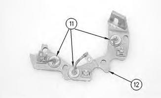
28. Press bushing (43) from housing (14) .
Note: Do not strike the diodes. The shock of such an impact can damage the diodes. Use proper tools in order to press or pull the diodes from the mountings. Asmuch as 890 N (200 lb) of force may be needed to remove a diode.
29. Remove 3 diodes (13) from housing (14) .
Illustration 21
30. Remove diode (11) from heat sink (12) .
Copyright 1993 - 2021 Caterpillar Inc. All Rights Reserved. Private Network For SIS Licensees.
g00628072
Wed Feb 10 21:42:10 UTC+0530 2021
Product: WHEEL LOADER
Model: 950F II WHEEL LOADER 5SK01561
Configuration: 950F Series II Wheel Loader 5SK00743-UP (MACHINE) POWERED BY 3116 Engine
Disassembly and Assembly
Comfort Series Seat For Caterpillar Machines
Media Number -RENR2165-12
Air Suspension With Air Valve Knob Height AdjustmentAssemble
SMCS - 7324-016-AJ
Assembly Procedure
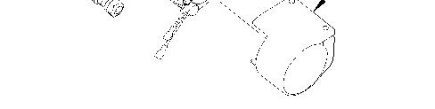
Illustration 1 g00891451
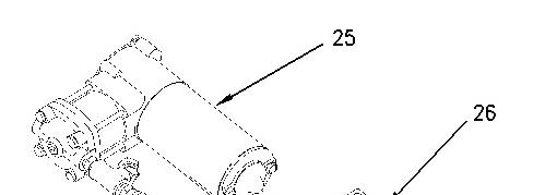
1. Install compressor assembly (25) to mount (26). Make sure that compressor assembly (25) isseated firmly in mount (26).
i01723170
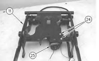
2
Install bolts (24) in order to attach compressor assembly (25) to scissor assembly (11).
3
Improper assembly of parts that are spring loadedcancause bodily injury.
To prevent possible injury, follow the established assembly procedure and wear protective equipment.
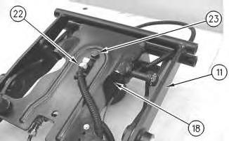
3. Install bolt (23) in order to attach spring assembly (18) to scissor assembly (11). Attach hose assembly (22) to spring assembly (18).
Illustration
g00872046
2.
Illustration
g00872043
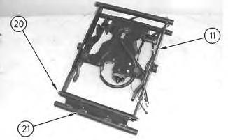
4
4. Install shaft (20) in order to attach toggle assembly (21) to scissor assembly (11). Tighten the two nuts for shaft (20) to a torque of 15 ±3 N·m (11 ± 2 lb ft).
Illustration 5
g00872031
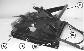
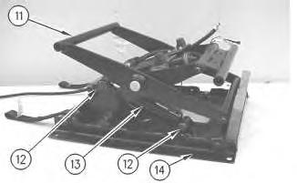
5. Install shaft assemblies (19) in order to attach tether straps (11A) and scissor assembly (11) to housing assembly (14). Tighten the nutson shaft assemblies (19) to a torque of 20 ± 5 N·m (15 ± 4 lb ft). Install blocking in order to prevent scissor assembly (11) from falling.
Illustration 6
g00872029
Illustration
g00872037
7
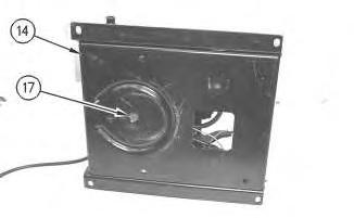
6. Install screw(17) in order to attach housing assembly (14) to spring assembly (18).
7. Install shaft (15) in order to attach toggle assembly (16) to scissor assembly (11). Tighten the two nuts for shaft (15) to a torque of 15 ±3 N·m (11 ± 2 lb ft).
8 g00897454
Illustration
Illustration
9
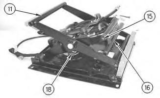
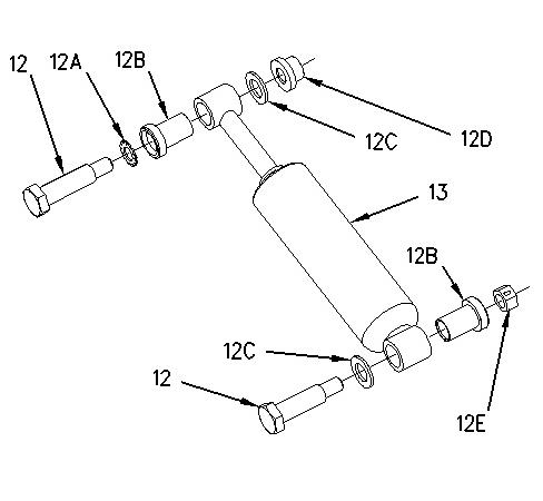
8. Install bearings (12B) to shock absorber (13).
9. Install bolts (12) in order to attach shock absorber (13) to scissor assembly (11) and housing assembly (14). Remove the blocking.
Note: Illustration 8 shows the location of lockwasher (12A), bearings (12B), washers (12C), nut (12D), and locknut (12E).
10. Repeat Steps 8 and 9 if the seat is equipped with a shock absorber on the opposite side.
Illustration 10
g00871994
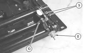
11. Connect harness assemblies (9) and hose assembly (10) to air valve (8).
Illustration
g00872007
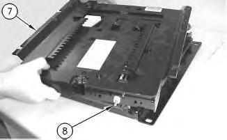
Illustration 11 g00871971
12. Position air valve (8) to upper housing assembly (7). Position upper housing assembly (7) to the seat.
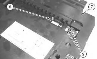
Illustration 12 g00871951
13. Install cable strap (6) in order to secure harness assemblies (9) to upper housing assembly (7).
Illustration 13 g00876043
This is the sample of the manual click on the download link for complete manual